1
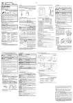
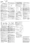
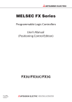
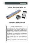
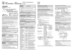
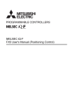
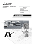
JY997D16401B Side ENGLISH 1. Outline The FX3U-2HSY-ADP high-speed output special adapter (hereinafter called high-speed output special adapter) is a special adapter dedicated to FX 3U Series PLC. It outputs pulse signals of a differential line driver system for applicable Servo Amplifiers (or Drive Unit) of an AC servomotor or stepper motor. Up to two units of this special adapter can be connected to the main unit per system. → For system configuration, refer to the FX3U Series User's Manual - Hardware Edition. FX3U-2HSY-ADP INSTALLATION MANUAL JY997D16401 Revision B [4] [5] 2-φ4.5 Mounting holes [6] Check if the following product and items are included in the package: [9] [8] POWER [3] Y4/6 Y5/7 [7] FP RP Manual PLS DIR [2] POWER [1] This manual FP RP December 2005 2005 Mitsubishi Electric Corporation SGB - Y5/7 + [12] [10] 1.2 Output Number and Signal When power is turned on, the output numbers and signals of the high-speed output special adapters are allocated as shown in the table below in the order of it near the main unit. Second unit First unit HighHighHighHighAnalog Analog Analog speed speed speed special special special speed input output output input function function function special special special special adapter adapter adapter adapter adapter adapter adapter 15.5 (0.62") Output LED [8] Special adapter connector cover [2] or [5] is removed Output number Name First Second unit unit Y0/2 Y000 Y002 Terminal layout of [6] Indicates that incorrect handling may cause hazardous conditions, resulting in death or severe injury. Indicates that incorrect handling may cause hazardous conditions, resulting in medium or slight personal injury or physical damage. Depending on circumstances, procedures indicated by linked to serious results. In any case, it is important to follow the directions for usage. 74 (2.92") Main unit Expansion board*1 This manual classify the safety precautions into two categories: . *1 A function extension board is required to use the high-speed I/O special adapter together with a communication/analog special adapter. → For system configuration, refer to the FX3U Series User's Manual - Hardware Edition. Output number Status of output form setting switch Signal name FP•RP side may also be First unit Output number Name First Second unit unit Y0/2+ Y000+ Y002+ Y0/2- Y000- Second unit Y4/6- Y004SGA Y1/3 Y001 Y003 Y4/6 Y004 Y006 Y5/7 Y005 Y007 [13] [7] Output mode setting switch Y006- Name SGA Setting SGA Y1/3+ Y001+ Y003+ Upper FP RP side Fwd pulse train (FP) Rev pulse train (RP) Y003 Y1/3- Y001- Lower Pulse train + direction Y007 Y5/7+ Y005+ Y007+ 2nd axis 1st axis 2nd axis Forward pulse train (FP) Y000 Y001 Y002 Reverse pulse train (RP) Y004 Y005 Y006 SG SG1 SG2 SG3 SG4 Pulse train Y000 Y001 Y002 Y003 Direction Y004 Y005 Y006 Y007 SG SG1 SG2 SG3 SG4 Y5/7- Y005SGB SGB Y003- PLS DIR • Cut off all phases of the power source externally before starting the installation or wiring work, thus avoiding electric shock or damages to the product. INSTALLATION PRECAUTIONS • Use the product in the environment within the general specifications described in PLC main unit manual (Hardware Edition). Never use the product in areas with dust, oily smoke, conductive dusts, corrosive gas (salt air, Cl 2 , H 2 S, NH 3 , SO 2 , or NO 2 ), flammable gas, vibrations or impacts, or expose it to high temperature, condensation, or wind and rain. If the product is used in such a place described above, electrical shock, fire, malfunction, damage, or deterioration may be caused. • When drilling screw holes or wiring, cutting chips or wire chips should not enter ventilation slits. Such an accident may cause fire, failure or malfunction. • Do not touch the conductive parts of the product directly, thus avoiding failure or malfunction. • Fix the special adapter securely to the specified connector. Incorrect connection may cause malfunction. 2.1 Connection to the FX3U Series PLC [14] Y002- Y4/6+ Y004+ Y006+ 1st axis Associated Manuals 15.1 (0.60") 17.6 (0.70") 7 (0.28") Safety Precaution (Read these precautions before use.) and SGB - Y5/7 + - Y1/3 + SGA - Y4/6 + - Y0/2 + PLS DIR - Y1/3 + SGA - Y4/6 + Y4/6 Y5/7 Effective Dec. 2005 Specifications are subject to change without notice. INSTALLATION PRECAUTIONS FX3U -2HSY-ADP Y0/2 Y1/3 This manual describes the part names, dimensions, mounting, and specifications of the product. Before use, read this manual and manuals of relevant products fully to acquire proficiency in handling and operating the product. Make sure to learn all the product information, safety information, and precautions. And, store this manual in a safe place so that you can take it out and read it whenever necessary. Always forward it to the end user. Registration The company name and the product name to be described in this manual are the registered trademarks or trademarks of each company. [11] [10] Y0/2 Y1/3 FX3U -2HSY-ADP Date The product can be mounted on DIN rail (DIN46277) or mounted directly using screws. For installation/uninstallation and safety precautions, refer to the following manual, too: → Refer to the FX3U Series User's Manual - Hardware Edition. 1.3 External Dimensions, Part Names, and Terminal Layout 1.1 Incorporated Items Products Manual Number 2. Installation 2) During STOP or PLC power off modes, set the output form operation. Do not set the output form operation during pulse train output. • Refer to the procedure 2) for configuring a new system. • Refer to the procedure 1) for adding product to an existing system. Procedure 1) Turn off the power. Disconnect all the cables connected to the PLC main unit and special adapter. Dismount the main unit and special adapter mounted on DIN rail or mounted directly using screws. 2) Install an expansion board to the main unit. For installation of expansion board, refer to the following manual: → Refer to the FX3U Series User's Manual - Hardware Edition 3) Remove the high-speed I/O special adapter connector cover (Right fig. A) and the special adapter connector cover (Right fig. B) on the main unit. 4) In case of connecting this product to a highspeed I/O special adapter as an addition, please replace the 'main unit' in the above description with a 'special adapter' and 3) C perform the procedure as indicated. (Please 4) 4) replace the following procedures similarly.) B 4) Slide the special adapter slide lock (Right fig.C) of the main unit. IN Y007- Unit : mm (inches) Weight: 80 g (0.18 lbs) SGB FX RU JY997D16501 MODEL CODE: 09R516 Expl ains FX 3U Ser ies PLC specification details for I/O, wir ing, installation, and maintenance. FX3U/FX3UC Series Programming Manual - Basic & Applied Instruction Edition JY997D16601 MODEL CODE: 09R517 Describes PLC programming for basic/applied instructions and devices. FX3U/FX3UC Series User’s Manual - Positioning Control Edition JY997D16801 MODEL CODE: 09R620 Describes positioning control and programming using FX 3U/ FX3UC Series PLC How to obtain manuals For the necessary product manuals or documents, consult with the Mitsubishi Electric dealer from where you purchase your product. Caution 1) When a high-speed output adapter is connected, the same output number is allocated to both the main unit and this adapter. Use either output terminal and do not wire to the unused output terminal. The outputs from the high-speed output special adapter and main unit are operated as below: Output operation Main unit High-speed output special adapter Transistoroutput type Relay-output type PLSY,PLSR,DSZR, DVIT,TBL,ZRN, PLSV,DRVI,DRVA Operated Operated*1 While instruction is activated, relevant output is ON. (LED is also ON.) PWM Operated Operated Do not apply PWM instruction for rel ay- output ty pe mai n unit.*2 instructions Applicable Standard FX3U-2HSY-ADP complies with EC directive (EMC Directive) and UL standards (UL, cUL). Further information can be found in the following manual. → Refer to FX3U Series Hardware Manual (Manual No. JY997D18801) Other Operated Operated Operated *1 The output frequency of transistor outputs in the main unit is a maximum of 100kHz. If the load is operated using pulses at a frequency more than 100kHz, PLC may be damaged. *2 PWM instruction has not supported the relay output for the reasons of the response delay of the output, chattering of contact, the contact life, etc. 3. Used cables and Tightening Torque on Terminal For connection example and wiring, refer to the following manual. → Refer to FX3U Series User's Manual - Hardware Edition. WIRING PRECAUTIONS • Cut off all phases of power source externally, before installation or wiring work in order to avoid electric shock or damage of product. WIRING PRECAUTIONS • Never let cutting chips and wire chips enter the ventilation slits of this product or PLC when performing wiring. Otherwise, fire, failure or malfunction may occur. • Make sure to observe the precautions below in order to prevent any damage to a machine or any accident which might be caused by abnormal data written in the PLC due to the influence of noise: 1)Do not lay close or bundle with the main circuit, high-voltage power line, or load line. Otherwise effects of noise or surge induction are likely to take place. Keep a safe distance of more than 100 mm (3.94") from the above when wiring. 2)Ground the shield wire or shield of a shielded cable at one point on the PLC. However, do not ground at the same point as high voltage lines. • Observe the following items to wire the lines to the European terminal board. Failing to do so may cause electric shock, short circuit, disconnection, or damage of the product. - The disposal size of the cable end should follow the dimensions described in this manual. - Tighten to a torque should follow the torque described in this manual. - Twist the end of strands and make sure there is no loose wires. - Do not solder-plate the electric wire ends. - Connect only the electric wires of regulation size. - Fix the electric wires so that the terminal block and connected parts of electric wires are not directly stressed. 1) Wire size To connect to the desired unit, use a shielded twisted pair cable having a conductor(s) of size AWG22-20. 2) Applicable cable Type Wire size Single-wire 0.3mm2 to 0.5mm2 (AWG22 to 20) 2-wire 2 pieces of 0.3mm2 (AWG22) Manufacturer Model Caulking tool Phoenix Contact Co., Ltd. AI 0.5-8WH CRIMPFOX UD6 - Stick terminal with insulating sleeve Insulation sleeve Contact area 8mm (0.31") 9mm (0.35") 2.6mm(0.1") 14mm(0.55") When using a stick terminal with insulating sleeve, choose a wire with proper cable sheath referring to the above outside dimensions, or otherwise, the wire cannot be inserted easily. The tightening torque must be 0.22 to 0.25N•m. OP C C D 3U FX3U-48M FX -2H R/ES SY -ADP FX 8M -48M FX -4 6) N RU OP ST 5) 6) 6) 5) 5) C Connection precautions • Install the expansion board to be used before connecting a special adapter. • Install an expansion board when using a special adapter other than a highspeed I/O special adapter in combination with a high-speed I/O special adapter. • Connect all the high-speed I/O special adapters before connecting other special adapters when they are used in combination. Do not connect a high-speed I/O special adapter on the left side of a communication or analog special adapter. 4.5 Output Interface Internal Circuit For connection example and wiring, refer to the following manual. → Refer to FX3U/FX3UC Series User's Manual - Positioning Control Edition STARTUP AND MAINTENANCE PRECAUTIONS High-speed output special adapter • Do not disassemble or modify the unit. Doing so may cause failure, malfunction or fire. * For repair, contact your local Mitsubishi Electric distributor. • Do not drop the product or do not exert strong impact, doing so may cause damage. 5V Equivalent to AM26C31 Servo Amplifier (or Drive Unit) *1 Y00 + Y00 - *1 SGA DISPOSAL PRECAUTIONS *3 Grounding (Ground resistance: 100Ω or less) SGA*2 • Please contact a company certified in the disposal of electronic waste for environmentally safe recycling and disposal of your device. 5V TRANSPORT AND STORAGE PRECAUTIONS • During transportation avoid any impact as the product is a precision instrument. Check the operation of the product after transportation. Equivalent to AM26C31 Servo Amplifier (or Drive Unit) *1 Y00 + Y00 - *1 SGB SGB*2 4.1 Applicable PLC Model name FX3U Series PLC Applicability The version number can be checked by monitoring D8001 as the last three digits indicate it. Note Cannot be connected to FX3UC-32MT-LT. 4.2 General Specifications For general specifications, refer to the manual of the PLC main unit. The items other than the following are equivalent to those of the PLC main unit. → Refer to FX3U Series User's Manual - Hardware Edition. Item Specification Dielectric 500V AC for one minute Conforming to JEM-1021 withstand voltage Between output ter minal of highInsulation 5MΩ or more by 500V speed output special adapter and ground terminal of PLC main unit resistance DC megger Item Grounding (Ground resistance: 100Ω or less) *1 Y00 indicates output number of the high-speed output special adapter. *2 'SGA' is insulated from 'SGB'. *3 Ground properly with reference to the Servo Amplifier (or Drive Unit) manual. If not indicated, ground as below. Grounding Ground properly with reference to the Servo Amplifier (or Drive Unit) manual. If not indicated, ground as below. - Grounding (when not indicated) - The grounding resistance should be 100Ω or less. - Independent grounding should be performed for best results. When independent grounding is not performed, perform "shared grounding" of the following figure. → For details, refer to the FX3U Series User's Manual - Hardware Edition. PLC Another equipment PLC Another equipment PLC Another equipment Specification Output circuit 60mA for 24V DC driving power supply Internally supplied from the main unit service power supply. Adapter driving power supply *3 Ver. 2.20 (from the first product) and later 4.3 Power Supply Specification 3) Termination of cable end Strip the coating of strand wire and twist the cable core before connecting it, or strip the coating of single wire before connecting it. An alternative connection is to use a ferrule with insulating sleeve. - Strand wire/single wire 4. Specification A 5) Connect the highspeed I/O special adapter (Right fig.D) to the main unit as shown on the right. 6) Slide back the special adapter slide lock (Right fig.C) of the main unit to fix the highspeed I/O special adapter (Right fig.C). -48M N ST R E W O P 3 1/ Y 2 7 0/ 5/ Y Y 6 P 4/ .R Y FP FX3U Series User’s Manual - Hardware Edition [1] DIN rail mounting groove (DIN rail: DIN46277) [2] High-speed I/O special adapter connector cover: Remove this cover for connecting high-speed I/O special adapter on the left side. [3] Name plate [4] Special adapter slide lock: Used to connect special adapter on left side of this special adapter. [5] Special adapter connector cover: Remove this cover for connecting special adapter on the left side. [6] Output terminal block (European type): Connected to Servo Amplifier (or Drive Unit) to which pulse signal of differential line driver system can be input. [7] Output form setting switch Either "Forward pulse train (FP)/Reverse pulse train (RP)" or "pulse train + direction" is selected. For setting, refer to the following manual. → Refer to FX3U / FX3UC Series User's Manual - Positioning Control Edition. [8] Output LED (red): Lit when output turns ON (if output turns ON and OFF alternately at high speed, LED flickers fast). [9] POWER LED (green): Lit while power is properly supplied from main unit. [10] Direct mounting hole:2 holes of φ4.5 (0.18") (mounting screw: M4 screw) [11] Special adapter fixing hook [12] DIN rail mounting hook [13] Special adapter connector: Used to connect communication special adapter or analog special adapter to this adapter on left side. [14] High-speed I/O special adapter connector: Used to connect high-speed I/O special adapter to this adapter on left side. 3U Description 1 3U PLS•DIR side Manual No. 3U Manual name 10 FX3U-48M -4 8M R /E S B JAPANESE FX A 3U Side 90 (3.55") 98 (3.86") 106 (4.18") B - Y0/2 + Side 30mA for 5V DC 5V DC power is supplied internally from the main unit. Independent grounding Best condition Shared grounding Good condition Common grounding Not allowed - The grounding wire size should be AWG 14 (2 mm2) or larger. - The grounding point should be close to the PLC, and all grounding wire should be as short as possible. 4.4 Performance Specification Item Specification Number of controlled axis Independent two axes Output points 4 points (Not counted among the total I/O points of the PLC.) Output system Differential line driver (Equivalent to AM26C31) Output form Forward pulse train, reverse pulse train, or pulse train + direction Load current 25 mA or less Maximum output frequency 200 kHz Insulation • External cables of output area are insulated from PLC by photo coupler or transformer. • SG are insulated from each other by transformer. Wiring length Maximum 10m (32' 9") This manual confers no industrial property rights or any rights of any other kind, nor does it confer any patent licenses. Mitsubishi Electric Corporation cannot be held responsible for any problems involving industrial property rights which may occur as a result of using the contents noted in this manual. Warranty Mitsubishi will not be held liable for damage caused by factors found not to be the cause of Mitsubishi; machine damage or lost profits caused by faults in the Mitsubishi products; damage, secondary damage, accident compensation caused by special factors unpredictable by Mitsubishi; damages to products other than Mitsubishi products; and to other duties. For safe use • This product has been manufactured as a general-purpose part for general industries, and has not been designed or manufactured to be incorporated in a device or system used in purposes related to human life. • Before using the product for special purposes such as nuclear power, electric power, aerospace, medicine or passenger movement vehicles, consult with Mitsubishi Electric. • This product has been manufactured under strict quality control. However when installing the product where major accidents or losses could occur if the product fails, install appropriate backup or failsafe functions in the system. HEAD OFFICE : TOKYO BUILDING, 2-7-3 MARUNOUCHI, CHIYODA-KU, TOKYO 100-8310, JAPAN HIMEJI WORKS : 840, CHIYODA CHO, HIMEJI, JAPAN JY997D16401B Side ENGLISH 1. Outline The FX3U-2HSY-ADP high-speed output special adapter (hereinafter called high-speed output special adapter) is a special adapter dedicated to FX 3U Series PLC. It outputs pulse signals of a differential line driver system for applicable Servo Amplifiers (or Drive Unit) of an AC servomotor or stepper motor. Up to two units of this special adapter can be connected to the main unit per system. → For system configuration, refer to the FX3U Series User's Manual - Hardware Edition. FX3U-2HSY-ADP INSTALLATION MANUAL JY997D16401 Revision B [4] [5] 2-φ4.5 Mounting holes [6] Check if the following product and items are included in the package: [9] [8] POWER [3] Y4/6 Y5/7 [7] FP RP Manual PLS DIR [2] POWER [1] This manual FP RP December 2005 2005 Mitsubishi Electric Corporation SGB - Y5/7 + [12] [10] 1.2 Output Number and Signal When power is turned on, the output numbers and signals of the high-speed output special adapters are allocated as shown in the table below in the order of it near the main unit. Second unit First unit HighHighHighHighAnalog Analog Analog speed speed speed special special special speed input output output input function function function special special special special adapter adapter adapter adapter adapter adapter adapter 15.5 (0.62") Output LED [8] Special adapter connector cover [2] or [5] is removed Output number Name First Second unit unit Y0/2 Y000 Y002 Terminal layout of [6] Indicates that incorrect handling may cause hazardous conditions, resulting in death or severe injury. Indicates that incorrect handling may cause hazardous conditions, resulting in medium or slight personal injury or physical damage. Depending on circumstances, procedures indicated by linked to serious results. In any case, it is important to follow the directions for usage. 74 (2.92") Main unit Expansion board*1 This manual classify the safety precautions into two categories: . *1 A function extension board is required to use the high-speed I/O special adapter together with a communication/analog special adapter. → For system configuration, refer to the FX3U Series User's Manual - Hardware Edition. Output number Status of output form setting switch Signal name FP•RP side may also be First unit Output number Name First Second unit unit Y0/2+ Y000+ Y002+ Y0/2- Y000- Second unit Y4/6- Y004SGA Y1/3 Y001 Y003 Y4/6 Y004 Y006 Y5/7 Y005 Y007 [13] [7] Output mode setting switch Y006- Name SGA Setting SGA Y1/3+ Y001+ Y003+ Upper FP RP side Fwd pulse train (FP) Rev pulse train (RP) Y003 Y1/3- Y001- Lower Pulse train + direction Y007 Y5/7+ Y005+ Y007+ 2nd axis 1st axis 2nd axis Forward pulse train (FP) Y000 Y001 Y002 Reverse pulse train (RP) Y004 Y005 Y006 SG SG1 SG2 SG3 SG4 Pulse train Y000 Y001 Y002 Y003 Direction Y004 Y005 Y006 Y007 SG SG1 SG2 SG3 SG4 Y5/7- Y005SGB SGB Y003- PLS DIR • Cut off all phases of the power source externally before starting the installation or wiring work, thus avoiding electric shock or damages to the product. INSTALLATION PRECAUTIONS • Use the product in the environment within the general specifications described in PLC main unit manual (Hardware Edition). Never use the product in areas with dust, oily smoke, conductive dusts, corrosive gas (salt air, Cl 2 , H 2 S, NH 3 , SO 2 , or NO 2 ), flammable gas, vibrations or impacts, or expose it to high temperature, condensation, or wind and rain. If the product is used in such a place described above, electrical shock, fire, malfunction, damage, or deterioration may be caused. • When drilling screw holes or wiring, cutting chips or wire chips should not enter ventilation slits. Such an accident may cause fire, failure or malfunction. • Do not touch the conductive parts of the product directly, thus avoiding failure or malfunction. • Fix the special adapter securely to the specified connector. Incorrect connection may cause malfunction. 2.1 Connection to the FX3U Series PLC [14] Y002- Y4/6+ Y004+ Y006+ 1st axis Associated Manuals 15.1 (0.60") 17.6 (0.70") 7 (0.28") Safety Precaution (Read these precautions before use.) and SGB - Y5/7 + - Y1/3 + SGA - Y4/6 + - Y0/2 + PLS DIR - Y1/3 + SGA - Y4/6 + Y4/6 Y5/7 Effective Dec. 2005 Specifications are subject to change without notice. INSTALLATION PRECAUTIONS FX3U -2HSY-ADP Y0/2 Y1/3 This manual describes the part names, dimensions, mounting, and specifications of the product. Before use, read this manual and manuals of relevant products fully to acquire proficiency in handling and operating the product. Make sure to learn all the product information, safety information, and precautions. And, store this manual in a safe place so that you can take it out and read it whenever necessary. Always forward it to the end user. Registration The company name and the product name to be described in this manual are the registered trademarks or trademarks of each company. [11] [10] Y0/2 Y1/3 FX3U -2HSY-ADP Date The product can be mounted on DIN rail (DIN46277) or mounted directly using screws. For installation/uninstallation and safety precautions, refer to the following manual, too: → Refer to the FX3U Series User's Manual - Hardware Edition. 1.3 External Dimensions, Part Names, and Terminal Layout 1.1 Incorporated Items Products Manual Number 2. Installation 2) During STOP or PLC power off modes, set the output form operation. Do not set the output form operation during pulse train output. • Refer to the procedure 2) for configuring a new system. • Refer to the procedure 1) for adding product to an existing system. Procedure 1) Turn off the power. Disconnect all the cables connected to the PLC main unit and special adapter. Dismount the main unit and special adapter mounted on DIN rail or mounted directly using screws. 2) Install an expansion board to the main unit. For installation of expansion board, refer to the following manual: → Refer to the FX3U Series User's Manual - Hardware Edition 3) Remove the high-speed I/O special adapter connector cover (Right fig. A) and the special adapter connector cover (Right fig. B) on the main unit. 4) In case of connecting this product to a highspeed I/O special adapter as an addition, please replace the 'main unit' in the above description with a 'special adapter' and 3) C perform the procedure as indicated. (Please 4) 4) replace the following procedures similarly.) B 4) Slide the special adapter slide lock (Right fig.C) of the main unit. IN Y007- Unit : mm (inches) Weight: 80 g (0.18 lbs) SGB FX RU JY997D16501 MODEL CODE: 09R516 Expl ains FX 3U Ser ies PLC specification details for I/O, wir ing, installation, and maintenance. FX3U/FX3UC Series Programming Manual - Basic & Applied Instruction Edition JY997D16601 MODEL CODE: 09R517 Describes PLC programming for basic/applied instructions and devices. FX3U/FX3UC Series User’s Manual - Positioning Control Edition JY997D16801 MODEL CODE: 09R620 Describes positioning control and programming using FX 3U/ FX3UC Series PLC How to obtain manuals For the necessary product manuals or documents, consult with the Mitsubishi Electric dealer from where you purchase your product. Caution 1) When a high-speed output adapter is connected, the same output number is allocated to both the main unit and this adapter. Use either output terminal and do not wire to the unused output terminal. The outputs from the high-speed output special adapter and main unit are operated as below: Output operation Main unit High-speed output special adapter Transistoroutput type Relay-output type PLSY,PLSR,DSZR, DVIT,TBL,ZRN, PLSV,DRVI,DRVA Operated Operated*1 While instruction is activated, relevant output is ON. (LED is also ON.) PWM Operated Operated Do not apply PWM instruction for rel ay- output ty pe mai n unit.*2 instructions Applicable Standard FX3U-2HSY-ADP complies with EC directive (EMC Directive) and UL standards (UL, cUL). Further information can be found in the following manual. → Refer to FX3U Series Hardware Manual (Manual No. JY997D18801) Other Operated Operated Operated *1 The output frequency of transistor outputs in the main unit is a maximum of 100kHz. If the load is operated using pulses at a frequency more than 100kHz, PLC may be damaged. *2 PWM instruction has not supported the relay output for the reasons of the response delay of the output, chattering of contact, the contact life, etc. 3. Used cables and Tightening Torque on Terminal For connection example and wiring, refer to the following manual. → Refer to FX3U Series User's Manual - Hardware Edition. WIRING PRECAUTIONS • Cut off all phases of power source externally, before installation or wiring work in order to avoid electric shock or damage of product. WIRING PRECAUTIONS • Never let cutting chips and wire chips enter the ventilation slits of this product or PLC when performing wiring. Otherwise, fire, failure or malfunction may occur. • Make sure to observe the precautions below in order to prevent any damage to a machine or any accident which might be caused by abnormal data written in the PLC due to the influence of noise: 1)Do not lay close or bundle with the main circuit, high-voltage power line, or load line. Otherwise effects of noise or surge induction are likely to take place. Keep a safe distance of more than 100 mm (3.94") from the above when wiring. 2)Ground the shield wire or shield of a shielded cable at one point on the PLC. However, do not ground at the same point as high voltage lines. • Observe the following items to wire the lines to the European terminal board. Failing to do so may cause electric shock, short circuit, disconnection, or damage of the product. - The disposal size of the cable end should follow the dimensions described in this manual. - Tighten to a torque should follow the torque described in this manual. - Twist the end of strands and make sure there is no loose wires. - Do not solder-plate the electric wire ends. - Connect only the electric wires of regulation size. - Fix the electric wires so that the terminal block and connected parts of electric wires are not directly stressed. 1) Wire size To connect to the desired unit, use a shielded twisted pair cable having a conductor(s) of size AWG22-20. 2) Applicable cable Type Wire size Single-wire 0.3mm2 to 0.5mm2 (AWG22 to 20) 2-wire 2 pieces of 0.3mm2 (AWG22) Manufacturer Model Caulking tool Phoenix Contact Co., Ltd. AI 0.5-8WH CRIMPFOX UD6 - Stick terminal with insulating sleeve Insulation sleeve Contact area 8mm (0.31") 9mm (0.35") 2.6mm(0.1") 14mm(0.55") When using a stick terminal with insulating sleeve, choose a wire with proper cable sheath referring to the above outside dimensions, or otherwise, the wire cannot be inserted easily. The tightening torque must be 0.22 to 0.25N•m. OP C C D 3U FX3U-48M FX -2H R/ES SY -ADP FX 8M -48M FX -4 6) N RU OP ST 5) 6) 6) 5) 5) C Connection precautions • Install the expansion board to be used before connecting a special adapter. • Install an expansion board when using a special adapter other than a highspeed I/O special adapter in combination with a high-speed I/O special adapter. • Connect all the high-speed I/O special adapters before connecting other special adapters when they are used in combination. Do not connect a high-speed I/O special adapter on the left side of a communication or analog special adapter. 4.5 Output Interface Internal Circuit For connection example and wiring, refer to the following manual. → Refer to FX3U/FX3UC Series User's Manual - Positioning Control Edition STARTUP AND MAINTENANCE PRECAUTIONS High-speed output special adapter • Do not disassemble or modify the unit. Doing so may cause failure, malfunction or fire. * For repair, contact your local Mitsubishi Electric distributor. • Do not drop the product or do not exert strong impact, doing so may cause damage. 5V Equivalent to AM26C31 Servo Amplifier (or Drive Unit) *1 Y00 + Y00 - *1 SGA DISPOSAL PRECAUTIONS *3 Grounding (Ground resistance: 100Ω or less) SGA*2 • Please contact a company certified in the disposal of electronic waste for environmentally safe recycling and disposal of your device. 5V TRANSPORT AND STORAGE PRECAUTIONS • During transportation avoid any impact as the product is a precision instrument. Check the operation of the product after transportation. Equivalent to AM26C31 Servo Amplifier (or Drive Unit) *1 Y00 + Y00 - *1 SGB SGB*2 4.1 Applicable PLC Model name FX3U Series PLC Applicability The version number can be checked by monitoring D8001 as the last three digits indicate it. Note Cannot be connected to FX3UC-32MT-LT. 4.2 General Specifications For general specifications, refer to the manual of the PLC main unit. The items other than the following are equivalent to those of the PLC main unit. → Refer to FX3U Series User's Manual - Hardware Edition. Item Specification Dielectric 500V AC for one minute Conforming to JEM-1021 withstand voltage Between output ter minal of highInsulation 5MΩ or more by 500V speed output special adapter and ground terminal of PLC main unit resistance DC megger Item Grounding (Ground resistance: 100Ω or less) *1 Y00 indicates output number of the high-speed output special adapter. *2 'SGA' is insulated from 'SGB'. *3 Ground properly with reference to the Servo Amplifier (or Drive Unit) manual. If not indicated, ground as below. Grounding Ground properly with reference to the Servo Amplifier (or Drive Unit) manual. If not indicated, ground as below. - Grounding (when not indicated) - The grounding resistance should be 100Ω or less. - Independent grounding should be performed for best results. When independent grounding is not performed, perform "shared grounding" of the following figure. → For details, refer to the FX3U Series User's Manual - Hardware Edition. PLC Another equipment PLC Another equipment PLC Another equipment Specification Output circuit 60mA for 24V DC driving power supply Internally supplied from the main unit service power supply. Adapter driving power supply *3 Ver. 2.20 (from the first product) and later 4.3 Power Supply Specification 3) Termination of cable end Strip the coating of strand wire and twist the cable core before connecting it, or strip the coating of single wire before connecting it. An alternative connection is to use a ferrule with insulating sleeve. - Strand wire/single wire 4. Specification A 5) Connect the highspeed I/O special adapter (Right fig.D) to the main unit as shown on the right. 6) Slide back the special adapter slide lock (Right fig.C) of the main unit to fix the highspeed I/O special adapter (Right fig.C). -48M N ST R E W O P 3 1/ Y 2 7 0/ 5/ Y Y 6 P 4/ .R Y FP FX3U Series User’s Manual - Hardware Edition [1] DIN rail mounting groove (DIN rail: DIN46277) [2] High-speed I/O special adapter connector cover: Remove this cover for connecting high-speed I/O special adapter on the left side. [3] Name plate [4] Special adapter slide lock: Used to connect special adapter on left side of this special adapter. [5] Special adapter connector cover: Remove this cover for connecting special adapter on the left side. [6] Output terminal block (European type): Connected to Servo Amplifier (or Drive Unit) to which pulse signal of differential line driver system can be input. [7] Output form setting switch Either "Forward pulse train (FP)/Reverse pulse train (RP)" or "pulse train + direction" is selected. For setting, refer to the following manual. → Refer to FX3U / FX3UC Series User's Manual - Positioning Control Edition. [8] Output LED (red): Lit when output turns ON (if output turns ON and OFF alternately at high speed, LED flickers fast). [9] POWER LED (green): Lit while power is properly supplied from main unit. [10] Direct mounting hole:2 holes of φ4.5 (0.18") (mounting screw: M4 screw) [11] Special adapter fixing hook [12] DIN rail mounting hook [13] Special adapter connector: Used to connect communication special adapter or analog special adapter to this adapter on left side. [14] High-speed I/O special adapter connector: Used to connect high-speed I/O special adapter to this adapter on left side. 3U Description 1 3U PLS•DIR side Manual No. 3U Manual name 10 FX3U-48M -4 8M R /E S B JAPANESE FX A 3U Side 90 (3.55") 98 (3.86") 106 (4.18") B - Y0/2 + Side 30mA for 5V DC 5V DC power is supplied internally from the main unit. Independent grounding Best condition Shared grounding Good condition Common grounding Not allowed - The grounding wire size should be AWG 14 (2 mm2) or larger. - The grounding point should be close to the PLC, and all grounding wire should be as short as possible. 4.4 Performance Specification Item Specification Number of controlled axis Independent two axes Output points 4 points (Not counted among the total I/O points of the PLC.) Output system Differential line driver (Equivalent to AM26C31) Output form Forward pulse train, reverse pulse train, or pulse train + direction Load current 25 mA or less Maximum output frequency 200 kHz Insulation • External cables of output area are insulated from PLC by photo coupler or transformer. • SG are insulated from each other by transformer. Wiring length Maximum 10m (32' 9") This manual confers no industrial property rights or any rights of any other kind, nor does it confer any patent licenses. Mitsubishi Electric Corporation cannot be held responsible for any problems involving industrial property rights which may occur as a result of using the contents noted in this manual. Warranty Mitsubishi will not be held liable for damage caused by factors found not to be the cause of Mitsubishi; machine damage or lost profits caused by faults in the Mitsubishi products; damage, secondary damage, accident compensation caused by special factors unpredictable by Mitsubishi; damages to products other than Mitsubishi products; and to other duties. For safe use • This product has been manufactured as a general-purpose part for general industries, and has not been designed or manufactured to be incorporated in a device or system used in purposes related to human life. • Before using the product for special purposes such as nuclear power, electric power, aerospace, medicine or passenger movement vehicles, consult with Mitsubishi Electric. • This product has been manufactured under strict quality control. However when installing the product where major accidents or losses could occur if the product fails, install appropriate backup or failsafe functions in the system. HEAD OFFICE : TOKYO BUILDING, 2-7-3 MARUNOUCHI, CHIYODA-KU, TOKYO 100-8310, JAPAN HIMEJI WORKS : 840, CHIYODA CHO, HIMEJI, JAPAN JY997D16401B Side ENGLISH 1. Outline The FX3U-2HSY-ADP high-speed output special adapter (hereinafter called high-speed output special adapter) is a special adapter dedicated to FX 3U Series PLC. It outputs pulse signals of a differential line driver system for applicable Servo Amplifiers (or Drive Unit) of an AC servomotor or stepper motor. Up to two units of this special adapter can be connected to the main unit per system. → For system configuration, refer to the FX3U Series User's Manual - Hardware Edition. FX3U-2HSY-ADP INSTALLATION MANUAL JY997D16401 Revision B [4] [5] 2-φ4.5 Mounting holes [6] Check if the following product and items are included in the package: [9] [8] POWER [3] Y4/6 Y5/7 [7] FP RP Manual PLS DIR [2] POWER [1] This manual FP RP December 2005 2005 Mitsubishi Electric Corporation SGB - Y5/7 + [12] [10] 1.2 Output Number and Signal When power is turned on, the output numbers and signals of the high-speed output special adapters are allocated as shown in the table below in the order of it near the main unit. Second unit First unit HighHighHighHighAnalog Analog Analog speed speed speed special special special speed input output output input function function function special special special special adapter adapter adapter adapter adapter adapter adapter 15.5 (0.62") Output LED [8] Special adapter connector cover [2] or [5] is removed Output number Name First Second unit unit Y0/2 Y000 Y002 Terminal layout of [6] Indicates that incorrect handling may cause hazardous conditions, resulting in death or severe injury. Indicates that incorrect handling may cause hazardous conditions, resulting in medium or slight personal injury or physical damage. Depending on circumstances, procedures indicated by linked to serious results. In any case, it is important to follow the directions for usage. 74 (2.92") Main unit Expansion board*1 This manual classify the safety precautions into two categories: . *1 A function extension board is required to use the high-speed I/O special adapter together with a communication/analog special adapter. → For system configuration, refer to the FX3U Series User's Manual - Hardware Edition. Output number Status of output form setting switch Signal name FP•RP side may also be First unit Output number Name First Second unit unit Y0/2+ Y000+ Y002+ Y0/2- Y000- Second unit Y4/6- Y004SGA Y1/3 Y001 Y003 Y4/6 Y004 Y006 Y5/7 Y005 Y007 [13] [7] Output mode setting switch Y006- Name SGA Setting SGA Y1/3+ Y001+ Y003+ Upper FP RP side Fwd pulse train (FP) Rev pulse train (RP) Y003 Y1/3- Y001- Lower Pulse train + direction Y007 Y5/7+ Y005+ Y007+ 2nd axis 1st axis 2nd axis Forward pulse train (FP) Y000 Y001 Y002 Reverse pulse train (RP) Y004 Y005 Y006 SG SG1 SG2 SG3 SG4 Pulse train Y000 Y001 Y002 Y003 Direction Y004 Y005 Y006 Y007 SG SG1 SG2 SG3 SG4 Y5/7- Y005SGB SGB Y003- PLS DIR • Cut off all phases of the power source externally before starting the installation or wiring work, thus avoiding electric shock or damages to the product. INSTALLATION PRECAUTIONS • Use the product in the environment within the general specifications described in PLC main unit manual (Hardware Edition). Never use the product in areas with dust, oily smoke, conductive dusts, corrosive gas (salt air, Cl 2 , H 2 S, NH 3 , SO 2 , or NO 2 ), flammable gas, vibrations or impacts, or expose it to high temperature, condensation, or wind and rain. If the product is used in such a place described above, electrical shock, fire, malfunction, damage, or deterioration may be caused. • When drilling screw holes or wiring, cutting chips or wire chips should not enter ventilation slits. Such an accident may cause fire, failure or malfunction. • Do not touch the conductive parts of the product directly, thus avoiding failure or malfunction. • Fix the special adapter securely to the specified connector. Incorrect connection may cause malfunction. 2.1 Connection to the FX3U Series PLC [14] Y002- Y4/6+ Y004+ Y006+ 1st axis Associated Manuals 15.1 (0.60") 17.6 (0.70") 7 (0.28") Safety Precaution (Read these precautions before use.) and SGB - Y5/7 + - Y1/3 + SGA - Y4/6 + - Y0/2 + PLS DIR - Y1/3 + SGA - Y4/6 + Y4/6 Y5/7 Effective Dec. 2005 Specifications are subject to change without notice. INSTALLATION PRECAUTIONS FX3U -2HSY-ADP Y0/2 Y1/3 This manual describes the part names, dimensions, mounting, and specifications of the product. Before use, read this manual and manuals of relevant products fully to acquire proficiency in handling and operating the product. Make sure to learn all the product information, safety information, and precautions. And, store this manual in a safe place so that you can take it out and read it whenever necessary. Always forward it to the end user. Registration The company name and the product name to be described in this manual are the registered trademarks or trademarks of each company. [11] [10] Y0/2 Y1/3 FX3U -2HSY-ADP Date The product can be mounted on DIN rail (DIN46277) or mounted directly using screws. For installation/uninstallation and safety precautions, refer to the following manual, too: → Refer to the FX3U Series User's Manual - Hardware Edition. 1.3 External Dimensions, Part Names, and Terminal Layout 1.1 Incorporated Items Products Manual Number 2. Installation 2) During STOP or PLC power off modes, set the output form operation. Do not set the output form operation during pulse train output. • Refer to the procedure 2) for configuring a new system. • Refer to the procedure 1) for adding product to an existing system. Procedure 1) Turn off the power. Disconnect all the cables connected to the PLC main unit and special adapter. Dismount the main unit and special adapter mounted on DIN rail or mounted directly using screws. 2) Install an expansion board to the main unit. For installation of expansion board, refer to the following manual: → Refer to the FX3U Series User's Manual - Hardware Edition 3) Remove the high-speed I/O special adapter connector cover (Right fig. A) and the special adapter connector cover (Right fig. B) on the main unit. 4) In case of connecting this product to a highspeed I/O special adapter as an addition, please replace the 'main unit' in the above description with a 'special adapter' and 3) C perform the procedure as indicated. (Please 4) 4) replace the following procedures similarly.) B 4) Slide the special adapter slide lock (Right fig.C) of the main unit. IN Y007- Unit : mm (inches) Weight: 80 g (0.18 lbs) SGB FX RU JY997D16501 MODEL CODE: 09R516 Expl ains FX 3U Ser ies PLC specification details for I/O, wir ing, installation, and maintenance. FX3U/FX3UC Series Programming Manual - Basic & Applied Instruction Edition JY997D16601 MODEL CODE: 09R517 Describes PLC programming for basic/applied instructions and devices. FX3U/FX3UC Series User’s Manual - Positioning Control Edition JY997D16801 MODEL CODE: 09R620 Describes positioning control and programming using FX 3U/ FX3UC Series PLC How to obtain manuals For the necessary product manuals or documents, consult with the Mitsubishi Electric dealer from where you purchase your product. Caution 1) When a high-speed output adapter is connected, the same output number is allocated to both the main unit and this adapter. Use either output terminal and do not wire to the unused output terminal. The outputs from the high-speed output special adapter and main unit are operated as below: Output operation Main unit High-speed output special adapter Transistoroutput type Relay-output type PLSY,PLSR,DSZR, DVIT,TBL,ZRN, PLSV,DRVI,DRVA Operated Operated*1 While instruction is activated, relevant output is ON. (LED is also ON.) PWM Operated Operated Do not apply PWM instruction for rel ay- output ty pe mai n unit.*2 instructions Applicable Standard FX3U-2HSY-ADP complies with EC directive (EMC Directive) and UL standards (UL, cUL). Further information can be found in the following manual. → Refer to FX3U Series Hardware Manual (Manual No. JY997D18801) Other Operated Operated Operated *1 The output frequency of transistor outputs in the main unit is a maximum of 100kHz. If the load is operated using pulses at a frequency more than 100kHz, PLC may be damaged. *2 PWM instruction has not supported the relay output for the reasons of the response delay of the output, chattering of contact, the contact life, etc. 3. Used cables and Tightening Torque on Terminal For connection example and wiring, refer to the following manual. → Refer to FX3U Series User's Manual - Hardware Edition. WIRING PRECAUTIONS • Cut off all phases of power source externally, before installation or wiring work in order to avoid electric shock or damage of product. WIRING PRECAUTIONS • Never let cutting chips and wire chips enter the ventilation slits of this product or PLC when performing wiring. Otherwise, fire, failure or malfunction may occur. • Make sure to observe the precautions below in order to prevent any damage to a machine or any accident which might be caused by abnormal data written in the PLC due to the influence of noise: 1)Do not lay close or bundle with the main circuit, high-voltage power line, or load line. Otherwise effects of noise or surge induction are likely to take place. Keep a safe distance of more than 100 mm (3.94") from the above when wiring. 2)Ground the shield wire or shield of a shielded cable at one point on the PLC. However, do not ground at the same point as high voltage lines. • Observe the following items to wire the lines to the European terminal board. Failing to do so may cause electric shock, short circuit, disconnection, or damage of the product. - The disposal size of the cable end should follow the dimensions described in this manual. - Tighten to a torque should follow the torque described in this manual. - Twist the end of strands and make sure there is no loose wires. - Do not solder-plate the electric wire ends. - Connect only the electric wires of regulation size. - Fix the electric wires so that the terminal block and connected parts of electric wires are not directly stressed. 1) Wire size To connect to the desired unit, use a shielded twisted pair cable having a conductor(s) of size AWG22-20. 2) Applicable cable Type Wire size Single-wire 0.3mm2 to 0.5mm2 (AWG22 to 20) 2-wire 2 pieces of 0.3mm2 (AWG22) Manufacturer Model Caulking tool Phoenix Contact Co., Ltd. AI 0.5-8WH CRIMPFOX UD6 - Stick terminal with insulating sleeve Insulation sleeve Contact area 8mm (0.31") 9mm (0.35") 2.6mm(0.1") 14mm(0.55") When using a stick terminal with insulating sleeve, choose a wire with proper cable sheath referring to the above outside dimensions, or otherwise, the wire cannot be inserted easily. The tightening torque must be 0.22 to 0.25N•m. OP C C D 3U FX3U-48M FX -2H R/ES SY -ADP FX 8M -48M FX -4 6) N RU OP ST 5) 6) 6) 5) 5) C Connection precautions • Install the expansion board to be used before connecting a special adapter. • Install an expansion board when using a special adapter other than a highspeed I/O special adapter in combination with a high-speed I/O special adapter. • Connect all the high-speed I/O special adapters before connecting other special adapters when they are used in combination. Do not connect a high-speed I/O special adapter on the left side of a communication or analog special adapter. 4.5 Output Interface Internal Circuit For connection example and wiring, refer to the following manual. → Refer to FX3U/FX3UC Series User's Manual - Positioning Control Edition STARTUP AND MAINTENANCE PRECAUTIONS High-speed output special adapter • Do not disassemble or modify the unit. Doing so may cause failure, malfunction or fire. * For repair, contact your local Mitsubishi Electric distributor. • Do not drop the product or do not exert strong impact, doing so may cause damage. 5V Equivalent to AM26C31 Servo Amplifier (or Drive Unit) *1 Y00 + Y00 - *1 SGA DISPOSAL PRECAUTIONS *3 Grounding (Ground resistance: 100Ω or less) SGA*2 • Please contact a company certified in the disposal of electronic waste for environmentally safe recycling and disposal of your device. 5V TRANSPORT AND STORAGE PRECAUTIONS • During transportation avoid any impact as the product is a precision instrument. Check the operation of the product after transportation. Equivalent to AM26C31 Servo Amplifier (or Drive Unit) *1 Y00 + Y00 - *1 SGB SGB*2 4.1 Applicable PLC Model name FX3U Series PLC Applicability The version number can be checked by monitoring D8001 as the last three digits indicate it. Note Cannot be connected to FX3UC-32MT-LT. 4.2 General Specifications For general specifications, refer to the manual of the PLC main unit. The items other than the following are equivalent to those of the PLC main unit. → Refer to FX3U Series User's Manual - Hardware Edition. Item Specification Dielectric 500V AC for one minute Conforming to JEM-1021 withstand voltage Between output ter minal of highInsulation 5MΩ or more by 500V speed output special adapter and ground terminal of PLC main unit resistance DC megger Item Grounding (Ground resistance: 100Ω or less) *1 Y00 indicates output number of the high-speed output special adapter. *2 'SGA' is insulated from 'SGB'. *3 Ground properly with reference to the Servo Amplifier (or Drive Unit) manual. If not indicated, ground as below. Grounding Ground properly with reference to the Servo Amplifier (or Drive Unit) manual. If not indicated, ground as below. - Grounding (when not indicated) - The grounding resistance should be 100Ω or less. - Independent grounding should be performed for best results. When independent grounding is not performed, perform "shared grounding" of the following figure. → For details, refer to the FX3U Series User's Manual - Hardware Edition. PLC Another equipment PLC Another equipment PLC Another equipment Specification Output circuit 60mA for 24V DC driving power supply Internally supplied from the main unit service power supply. Adapter driving power supply *3 Ver. 2.20 (from the first product) and later 4.3 Power Supply Specification 3) Termination of cable end Strip the coating of strand wire and twist the cable core before connecting it, or strip the coating of single wire before connecting it. An alternative connection is to use a ferrule with insulating sleeve. - Strand wire/single wire 4. Specification A 5) Connect the highspeed I/O special adapter (Right fig.D) to the main unit as shown on the right. 6) Slide back the special adapter slide lock (Right fig.C) of the main unit to fix the highspeed I/O special adapter (Right fig.C). -48M N ST R E W O P 3 1/ Y 2 7 0/ 5/ Y Y 6 P 4/ .R Y FP FX3U Series User’s Manual - Hardware Edition [1] DIN rail mounting groove (DIN rail: DIN46277) [2] High-speed I/O special adapter connector cover: Remove this cover for connecting high-speed I/O special adapter on the left side. [3] Name plate [4] Special adapter slide lock: Used to connect special adapter on left side of this special adapter. [5] Special adapter connector cover: Remove this cover for connecting special adapter on the left side. [6] Output terminal block (European type): Connected to Servo Amplifier (or Drive Unit) to which pulse signal of differential line driver system can be input. [7] Output form setting switch Either "Forward pulse train (FP)/Reverse pulse train (RP)" or "pulse train + direction" is selected. For setting, refer to the following manual. → Refer to FX3U / FX3UC Series User's Manual - Positioning Control Edition. [8] Output LED (red): Lit when output turns ON (if output turns ON and OFF alternately at high speed, LED flickers fast). [9] POWER LED (green): Lit while power is properly supplied from main unit. [10] Direct mounting hole:2 holes of φ4.5 (0.18") (mounting screw: M4 screw) [11] Special adapter fixing hook [12] DIN rail mounting hook [13] Special adapter connector: Used to connect communication special adapter or analog special adapter to this adapter on left side. [14] High-speed I/O special adapter connector: Used to connect high-speed I/O special adapter to this adapter on left side. 3U Description 1 3U PLS•DIR side Manual No. 3U Manual name 10 FX3U-48M -4 8M R /E S B JAPANESE FX A 3U Side 90 (3.55") 98 (3.86") 106 (4.18") B - Y0/2 + Side 30mA for 5V DC 5V DC power is supplied internally from the main unit. Independent grounding Best condition Shared grounding Good condition Common grounding Not allowed - The grounding wire size should be AWG 14 (2 mm2) or larger. - The grounding point should be close to the PLC, and all grounding wire should be as short as possible. 4.4 Performance Specification Item Specification Number of controlled axis Independent two axes Output points 4 points (Not counted among the total I/O points of the PLC.) Output system Differential line driver (Equivalent to AM26C31) Output form Forward pulse train, reverse pulse train, or pulse train + direction Load current 25 mA or less Maximum output frequency 200 kHz Insulation • External cables of output area are insulated from PLC by photo coupler or transformer. • SG are insulated from each other by transformer. Wiring length Maximum 10m (32' 9") This manual confers no industrial property rights or any rights of any other kind, nor does it confer any patent licenses. Mitsubishi Electric Corporation cannot be held responsible for any problems involving industrial property rights which may occur as a result of using the contents noted in this manual. Warranty Mitsubishi will not be held liable for damage caused by factors found not to be the cause of Mitsubishi; machine damage or lost profits caused by faults in the Mitsubishi products; damage, secondary damage, accident compensation caused by special factors unpredictable by Mitsubishi; damages to products other than Mitsubishi products; and to other duties. For safe use • This product has been manufactured as a general-purpose part for general industries, and has not been designed or manufactured to be incorporated in a device or system used in purposes related to human life. • Before using the product for special purposes such as nuclear power, electric power, aerospace, medicine or passenger movement vehicles, consult with Mitsubishi Electric. • This product has been manufactured under strict quality control. However when installing the product where major accidents or losses could occur if the product fails, install appropriate backup or failsafe functions in the system. HEAD OFFICE : TOKYO BUILDING, 2-7-3 MARUNOUCHI, CHIYODA-KU, TOKYO 100-8310, JAPAN HIMEJI WORKS : 840, CHIYODA CHO, HIMEJI, JAPAN