1
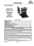
FOREWORD
0
0
This manual provides technical information on the use of
thisspecialfunction
block in connectionwiththe
FX
programmable controller.
Users shouldensurethatthedetails
of thismanual is
studied and understood before attempting to installor
use these units.
CONTENTS
1.
INTRODUCTION
1
2.
CONFIGURATION AND SPECIFICATIONS
2
3.
CONNECTION, WIRING
5
4.
ASSIGNMENT OF BUFFER MEMORY
7
5.
COUNTER MODES (BFM #O to #3)
10
6.
COMMAND SETTINGS (BFM # 4 to #15)
13
7.
CURRENT VALUE, STATUS INFORMATION (BFM #20 to #30)
15
8.
REQUIRED PROGRAMMING
18
9.
OPERATION, ABNORMALITY CHECK
19
10.
OUTLINE OF FROM/TO INSTRUCTION
20
1. INTRODUCTION
The FX-1HC hardware high-speed counter blockIs a 2-phase 50 kHz high-speed counter. It is a special extension block for theFX series programmable controller. The FX-1 HCcounts at a higher speed
than the built-in high-speed counter of the programmable controller (2-phase2 kHz, l-phase 10 kHz)
and performs comparisons and outputs directly.
(1) CompatiblePC8
(3) InputSignal
Versions 2.0 or later of the FX series of programmable controllers (those with serial nos. 13XXXX
or larger) may be used with theFX-1HC. This Is
because the FROM and TO commands are used
to transfer data between the programmable controller base unit and the FX-1 HC.
(2)
The source of your input signal should be a 1 or
2 phase encoder. A 5V, 12V, or 24V power
source can be used. An initial value setting command input (PRESET) and a count prohibit command input (DISABLE) are also available.
(4)
UnitConfiguration
TransistorOutput
When the counter value coincideswith their compare values, the appropriate output is set ON. A
PNP and an NPN output transistor is provlded
for both outputs to allow either sink or source
connection methods.
The casing of the FX-1HC unit resembles that of
the 16 I/O point extension block, but thenumber
of I/O points occupied by theFX-1 HCis actually
eight (you can count themas either input or output points). The FX-1HC unit consumes 70mA of
the 5V power supplied by the programmable controller, so you must take careto keep the total
power consumed byall the extension blocks
below the allowablelimit of your programmable
controller. The output circuit of your encoder or
the transistor outputs of this special block will require a separate power source.
(5)
Countermode
Various counter modes, such as 1-phase or 2phase, 16-bit or 32-bit modes, can be selected
using commands from the programmable controller. Allow the FX-1 HCunit to run onlyafter setting these mode parameters.
1
2. CONFIGURATION AND SPECIFICATIONS
~~
~
Performance Specifications
those for yourbase unit of the FX series.
The environmental specifications for theFX-1HC are the same as
1-phase input
1 input
inputs
2
Item
I
I
Sianallevel
frequency
I
I
I
5V,12V, or 24V
r
I
input signal
Pulse shape
t2
t3-
Format
Range
Counting
specification
Comparison
Type
2-phase input
1 edge count
I edge
2 count
+/-lo% (selected by terminalconnection)
50 kHz
11
I
I edge
4 count
7mA
kHzI
25
I 12.5 kHz
t l : Riselfall time is 3ps or less
t2:ON/OFF
pulse duration lops or more
t3:Phase
differencebetweenphase A and
phase B is3.*s or more
PRESET (2 phase) input 1OQa or more
DISABLE (count prohibit) input lO@s or more
Automatic UP/DOWN (however, when on 1 phase 1 input mode, UP/DOWN is determined by a programmable controller commandor an input terminal.)
When 32-bit is specified: -2,147,483,648 to +2,147,483,647
When 16-bit is specified: 0 to 65,535 luDDer limit can be user sDecifiedl
Each output is setwhen the present value of the counter matches with the compare
value (which is transferred from the programmable controller), andis switched OFF
by a reset command from the programmable controller.
YH: Direct output processedby hardware.
YS: Software processed output with worst delay time
of 300ps.
(Therefore, when the input frequency is
50 kHz, there is a worstcase delay of 15 input
pulses.)
3
2. CONFIGURATION AND SPECIFICATIONS
I
Output Signal
I
Types of outputs
Output capacity
I
1
0 Occupation
Power From Base
1
YHN: NPN transistor output for YH output
YHP: PNP transistor outout for YH outDut
YSN: NPN transistor ouiput for YS output
YSP: PNP transistor output
YSfor
output
r--------i
k-9
!
I
DC 12V to 24V 0.5A
8 points (but not addressed by X, Y relays)
DC 5V 70mA
I NPN
I PNP
I
I
I
3. CONNECTION, WIRING
,NPN
output encoders
can also be used.
- 7 1
and YHN, or YSP and
YSN together.
I
% Connect SO and the
grounded terminal at
the programmable controller sideas required.
5
X27
X28
*R X29
X30
X3 1
Terminal status
Cannot be used
Error status
Model identification code K4010 is written
Cannot be used
7
-
4. ASSIGNMENT OF BUFFER MEMORY
Data transfer between the FX-1 HC block and the Programmable Controller Is through the FX-1HC’s
RAM buffer memory (32 address locationseach of 16 bits) by the controller’s FROM/TO Instructions.
With reference to the table on the previous page:
W: These settings determine how the counting and the setting or resetting of the output is made.
The FX base unit should write to these areas before starting any count process.
R: These areas are for monitoring purposes.They are read only areas in which data can be readby
the FROM instruction but cannot be written by the TO instructions. If the TO instruction is
attempted on theseareas, the instruction is ignored.
R/W: These areas are read and writable. They can be read for monitoring purposes. They can also
be written to for resetting. Care should be taken
when writing to these areas asthe current data
will be lost.
0
Writehead examples
Dl and DO areThecontentsof
Thecontentsofdataregisters
writtenInto BFMs #13 and #12 ofspecialblockblock
No.2.
BFMs #21 and #20 ofspecial
No.2 areread to dataregisters D3and D2.
8
-.
.
..
__
4. ASSIGNMENT OF BUFFER MEMORY
9
.
BFM
(1)
#O
(a) 32-bit
counter
modes
Counter
mode
The counter mode is selected from the programmable controller.As shown below, values between KO and K1 l are written tobuffer memory
BFM #O from the programmable controller. When
you are about to begin, you must give a momentary command using M8002 (initial pulse) as the
condition contact of the TO instruction. A continuous command is not allowed.
Modes of KO to K11 of buffer memory BFM #O
I
Count Modes
edge
count
1
I (phase
2-phase input I
2 edge count
diffeience
I
pulse)
1
I
32 bits
4 edge count
1-phase 2-input (addlsubtract pulse)
1-phase 1-input
~~~
~
H/W UP/DOWN
S/W UP/DOWN
K10
KO
I
I
K1
K3
K4
K5
K6
K7
K8
K9
yr$:r
Lower
is limit
-2,147,483,648
A 32-bitbinarycounter
which executes UP/DOWN
countingwill changefrom
the lower limit to the upper
limit or theupper limit to
the lower limit when overflow occurs. Both the
upper and lower limits are
fixed values:
upper
the
limit
+2,147,483,647,
the and
lower
is limit -2,147,483,648.
(b) 16-bit counter modes
16 bits
K2
+2,147,483,647
A 16-bit binary counter handles only positive values
from 0 to 65,535.
Ring length
(BFM #3, #2)
K11
Changes to zero from the upper limitor to the upper
limit from zero when overflow occurs; the upper limit is
determined by BFMs +3 and #2.
H/W: Hardware
S/W: Software
10
5. COUNTER MODES fBFM #O to #3)
(2)
BFM #3, #2 Ring length
(3)
Stores the data to specify the lengthof the 16-bit
counter (default: K65,536).
(D)TO
K2
K2
KlOO
0
1-phase 1-input counter (K8 to K11)
Hardware UP/DOWN (K8 , K9)
Phare A
ON
UP/DOWN is
determined
by input
phase A
(ON/OFF).
ON
K1
In the above example, K100 is written into BFMs
#3 and X2 of special block No.2 as a 32-bit binary value (BFM#3 = O , BFM#2 = 100). Permitted values: K2 to K65,536.
0
98
99
0
1
Software UP/DOWN (K10, K11)
BFM +1
KO
Kl
UP/DOWN is
determined
by the contents of BFM
#1 , (KO/Kl).
ON
DOWN
1
98 0
99
When ring length KlOO is specified, the value of
the counter changes as shown above.
Current
value
11
DOWN
5. COUNTER MODE (BFM #O to #3)
(K6, K7)
1-phase
2-input
counter
(4)
ON
OFF
Phase A
input
Phase B
input
OFF
PhWA
input 1 at
OFF+ ON
-
ON
1
l
2
3
2 edge-count
counter
3
3
2
1
0
Phase A
Phase B
input + 1
at OFF -D ON
If both phase A and phase B inputs are received
simultaneously, the counter value does not
change.
(5)
Phase B
JTF
Phase B input OFF + ON Phase B input ON +OFF
(ON + OFF) Count up by (OFF +ON) Count down
by 1 each change.
1 each change.
4 edge-count counter (K4, K5)
2-phase counter (KO to K5)
1 edge-count-counter (KO, K1)
Phase
PhaseA
B
1
4
7
%
(K2, K3)
Phase A input 3
a
T
r
p
$
J
s
Phase B input OFF+ON
while phaseA input ON
Count up by 1.
I
Phase B input
Phase B input ON+OFF
while phaseA input ON
Count down by 1.
DOWN COUNT:
Phase A input
Phase B input
12
-+L;k
/=
I
6. COMMAND SETTINGS (BFM #4 to #15)
(1)
BFM #4 Command
5. When b4 = OFF, preset function
from
the
SET is disabled
PRE-
6. When b8 is set to ON, all error flags are reset.
7. When b9 is set to ON, YH output is reset.
8. When b10 is set to ON, YS output is reset.
9. When b l l is set to ON, YH output is set ON.
10.When b12 Is set to ON, YS output is set ON.
e Example Program >
Error flag rosa1
1. When bO is set to ON and the DISABLE input
output reset
terminal to OFF, the counter is permittedto
start counting input pulses.
2. Unless b l is set to ON, YH (hardware comIn the above program, M25 to M10 map onto b15
pared output) does not turnON.
to bO of BFM #4 of special block No.2.
3. Unless b2 is set to ON, YS (software comb4 to bO are turned ON at all times by M i 4 to
pared output) does not turnON
M10.
4. When b3 = ON, YS output is reset if YH output
(M18), b9 (M19), and b10 (M20) are conis set, and YH output is reset If YS output is b8
set. When b3 = OFF, y~ and ys outputs act in- trolled by the programmable controller inputs
dependently, and do not reset each other.
X004 and X005
13
6. COMMAND SETTINGS (BFM #4 to #15)
(3) BFM #13, #12 Compare value forYH output
0 After comparing the current value
of the
counter with the value written in BFM X13 and
#12, the hardware comparator In the FX-1HC
outputs the comparisonresult.
0 YH output will not turn ON if you use the preset or the TO instruction to set the preset
value equal to the counter value. it will turn
ON only when a match occurs by the counting
of input pulses.
(2) BFM #11, #10 Preset data
Data to be used as the initial value when the
counter starts t o count.
0 Data becomes valid when b4 is set to ON, and
PRESET input terminal changes fromOFF to
ON. The default value of the counter is zero.
You can change it by writing avalue into BFM
#11 and # l o or by using the abovecommand.
0 The initial value can also
be set by writing the
data directly into BFM #21 and #20 (current
value of the counter).
0
(4) BFM #15, X14 Comparison set value for YS
output
Write counter data with (D) TO
0 Count data is always handled as a pair from
two 16-bit values in this special counter block.
16-bit 2’s complement values stored in theregisters of the programmable controller cannot
be used.
0 When you are writing apositive value between
K32,768 and K65’535, the data shouldbe
treated as a 32-bit value even when a 16-bit
ring counter is used.
0 When transfering counter data to/from thisspecial counter block, alwavs use the 32-bit forms
of the FROM/TO instruciions ((D)FROM,
After comparing the current valueof the
counter with thevalue written into BFM #15 or
#14, the software comparatorIn the FX-1 HC
outputs the comparisonresult.
0 The comparison operation takes about300ps,
and if a match occurs, the output goesON.
0 The output will not turn ON if you use the preset or the TO Instruction toset the preset
value equal to the counter value. It will turn
ON only when a match occursby the counting
of input pulses.
0
14
..
7. CURRENT VALUE STATUS INFORMATION
(BFM #20 to #3d)
(1)Counter current value (BFM #21, 20)
The current value of the counter can be
read by the programmable controller. It
will not be the correct value during highspeed operations because of the communication delay. The current value of the
counter can be forciblychanged by writing a 32-bit value into the appropriate
BFMs from the programmable controller.
Although a match may occur while you
are rewriting, you will not get an output.
(2)Maximum count value (BFM #23, 22)
These store the maximum and minimum
values reached by the counter.If the
power is turned off, the stored data is
cleared.
(3)Comparison status (BFM #26)
bo
When '0' (OFF)
Set valuescurrent value
When '1' (ON)
Set value > current value
bl
Set value#current value
Set value = current value
BFM X26
I
I
I
YH
I
I
I
YS
b2
b3
I s t valuercurrent value I Setvalue
I Set vatuescurrent value I Setvalue
< current value
> current value
b4
Set value+current value
Set value = current value
b5
Set valuezcurrent value
Set value < current value
BFM #26 is only for reading only.
Wriie commands from the
programmable controller are ignored.
15
I
I
I
7. CURRENT VALUE STATUS INFORMATION
(BFM #20 to #3d)
(5) BFM #29 Error status
(4) Terminal status (BFM #27)
l2
Comarevalue
1.WhenBFM
#4 b4 = 1, the contents of BFMs
#11 and #10 are written into the
current value
register of the counter immediately after the
PRESET terminal changes to ON.
I
7-
I
iI BFM X4
L
#4 bO = 1, counting starts imme2.WhenBFM
diately after the DISABLE terminal changes to
OFF.
3.
f\Compare value
I
Coincidence output
b9, b10
7
f
I
Coincidence output
Error status in the FX-1HC can be checked by
reading the contents of bO to b7 of BFM #29 to
auxiliary relays of the programmable controller.
Outputoccurs when the current value becomes equal to the compare value but only if
b l and b2of BFM #4 are OFF. Once an output
is set, it remains ON until it is reset by b9 or
b10 of BFM #4. If b3 of BFM #4 is ON, however, one of the outputsis resetwhen the
other is set.
TO
K2
K29
K4M100
K1
Special block No.2 BFM #29 (b7 to bo) -(M107
to M100)
16
-.
I
.
.
.....
-
7. CURRENT VALUE STATUS INFORMATION
(BFM #20 to #3d)
I
(6) Model identification code number
BFM#30
The identification number for a Special Blockis
read by using the FROM command.
The identification number for the FX-1HC unit is
K4010.
By reading this identification number, theuser
may create built-in checking routinesto check
whether the physical positionof the FX-1 HC
matches to that of the software.
These error flags can be reset by b8 of BFM #4.
17
8. REQUIRED PROGRAMMING
Please use the following programas a guide whenever you use the FX-1HC unit. Other instructions to
read the current valueof the counter, status etc. can be added as required.
1. K11 is written into BFM #O of special block
No.2. The counter input is 16-bit 1 -phase.
Please use a pulse command for this initialization.
2. K1234 -. BFM #3, #2 (special block No.2)
The ring length can be specified
when a 16-bit counter is specified.
3. UP/DOWN direction should bespecified for
1- hase l-input software determined
U~DOWN
counter.
4. K1000 -. BFM #13, X12
Set the compare
value for YH output
5. Kg00 + BFM #15,X14 Set the compare
value for YS output (not necessary if
only YH output is used).
6. Note that counting only occursif count prohibit is OFF. Also, outputs will not be set from
the
counting processat all if the relevant outPreset allowed
ut prohibit are set in the command register.
x12
lease reset the error flags and YH/YS output
PLS
M18
before you start. The mutual reset and preset
reaet
Error
t
i
initialization commands can be used as required.
7. (M25 to M10) + BFM #4 (b15 to bo) command
b)
8. BFM (#21, #20)
18
+
Reads the current value to
the data registers D3 and
D2.
e Preliminary
Checks
>
1. Check that the I/O wiring and extension
cable of the FX-1 HC areproperly connected.
2. 5V 70mA power is supplied from the
base or extension units for the FX-1 HC.
Check that there is no power overload
from this and other extensionblocks.
3. The counter works correctly only when
data such as the counter mode (set with
a pulse command),theTO command, the
compare value, etc. are appropriately
specified. Remember to initialize the
count (BFM #4 bo), preset (BFM #4 b4),
and output (BFM #4 b2,bl) prohibits.
Reset the YH/YS outputs before you
start.
e Troubleshootlng >
The following LEDs on the main panelof the FX-1HC
may help youto troubleshoot the unit.
#A #B
Goes on/off as #A, #B input turn ON/OFF. It can
be checked by rotating the encoderslowly.
0
UP, DN
Lights up to indicate whether the counter is going
up (UP) or down (DN).
0
PRESET and DIS
The appropriate LED lights up when the PRESET
terminal or the DISABLE terminal is ON.
0
YH, YS
The appropriate LED lightsup when YH/YS output
is turned on.
You
the
check
can
error constatus
reading
the by
tent of BFM #29 to the programmable controller.
Error contents are shown on page17.
19
I O . OUTLINE OF FROM/TO INSTRUCTION
78 FNC
FROM
m[D
l
m2
K2
K20
*I
Dl20
n
K6
BFM #20 t o #25 of
special unit No. 2 + Dl20
25
to
m l : Special function unit or block number. These are numbered consecutively from KO t o K7
starting from the one closest to the base unit.
m2:Buffer
memory headaddress.(m2
=
KO to K31)
[De]: Transfer destination head address. T, C, D, KnM, KnY, KnS, V or 2 can be specified. This
argument can be coupled with an index register.
I
n:The
I
I
number of words t o be transferred (n = K1 to K32)
I
TOP
-1
ml
m2
[S
K2
K12
D112
n
K4
D l 12 t o D15
l transferred t o special block
No.0 BFM #12-#15
m l , m2, n: The same as above
[S.]: Transfer destination head address. T, C, D, KnX, KnY, KnM, KnS,
ified. This argument can be coupled with an index register.
V, 2, K or H can be spec-
When X10 or X1 1 is OFF, transfer is not executed, and data at the transfer destination will not be
changed.
20
__
--
-
Revisions
EDITION DATE
MANUAL NUMBER
REVISION
Jun.
1991
JY992D27301A
First edition
Aug.1991
JY992D27301 B
P.3 5 + 3.5ps.
P.11 initial value + default.
P. 12 (4) waveform corrected.
P.13 comparator O/P +output.
P.17 b2 b4 of table changed.
-
Apr.1992
JY992D27301 C
P.7 BFM #20, 21 : *R --. *R/W.
Sept.1993
JY992D27301 D
Text change : P. 1, 7, 13, 17.
Chapter 8 title : P. 18.
: P.7, 8.
R M I text
Under no circumstances will Mitsubishi Electric be liable or responsible for any
consequential damage that may arise as a result of the installation or use of this
equipment.
All examples and diagrams shownin this manual are intended only as an
aid to understanding the text, not to guarantee operation. Mitsubishi Electric will accept
no
responsibility for actual use
of the product based on these illustrative examples.
Owing to the very great varietyin possible applications of this equipment, you
must satisfy yourself as
to its suitability for your specific application.
A MlTSUBlSHl ELECTRIC CORPORATION
HEAD OFFICE:
HlMEJlWORKS:
JY992D27301 D
HI-IB-057-D (9309)(SEN)
@
MlTSUBlSHlDENKI BLDG MARUNOUCHI TOKYO 1W TELEX:J24532
840, CHIYODACHO.HIMEJI.JAPAN
CABLE MELCO TOKYO
Effective SEP. 1993
Specificationsaresubject
to change without notice.