1
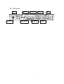
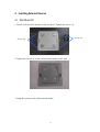
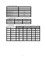
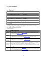
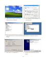
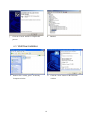
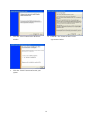
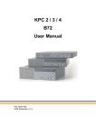
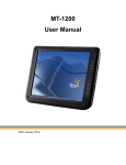
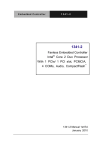
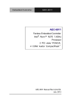
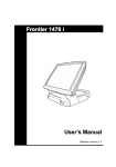
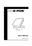
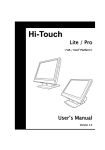
User Manual
February 2008
Revision 1.2
Kiosk System
Panel PC Series
Safety
IMPORTANT SAFETY INSTRUCTIONS
• Read these instructions carefully.
Keep these instructions for future reference.
• Follow all warnings and instructions marked on the product.
• Do not use this product near water.
• Do not place this product on an unstable cart, stand, or table.
The product may fall, causing
serious damage to the product.
• Slots and openings in the cabinet and the back or bottom are provided for ventilation; to
ensure reliable operation of the product and to protect it from overheating, these openings
must not be blocked or covered.
The openings should never be blocked by placing the
product on a bed, sofa, rug, or other similar surface. This product should never be placed
near or over a radiator or heat register, or in a built-in installation unless proper ventilation
is provided.
• This product should be operated from the type of power indicated on the marking label.
If
you are not sure of the type of power available, consult your dealer or local power company.
• Do not allow anything to rest on the power cord.
Do not locate this product where persons
will walk on the cord.
• Never push objects of any kind into this product through cabinet slots as they may touch
dangerous voltage points or short out parts that could result in a fire or electric shock.
Never spill liquid of any kind on the product.
• The socket outlet should be installed near the equipment and should be easily accessible.
PSE Mark
This device complies with the PSE rules. Operation is subject to the following two conditions:
This device may not cause harmful interference.
This device must accept any interference received, including interference that may cause
undesired operation.
Caution on Lithium Batteries
Danger will explosion if battery is incorrectly replaced.
equivalent type recommended by the manufacturer.
the manufacturer’s instructions.
2
Replace only with the same or
Dispose of used batteries according to
Table of Contents
Safety..................................................................................................................................2
1.
Accessories .................................................................................................................4
2.
Components ................................................................................................................4
2.1. Front View ...............................................................................................................4
2.2. Rear View ................................................................................................................5
2.3. Button Cover View...................................................................................................5
2.4. I/O Function.............................................................................................................6
3.
Specification ...............................................................................................................7
4.
Installing External Devices..........................................................................................9
4.1. Wall Mount Kit ........................................................................................................9
4.2. MSR......................................................................................................................... 11
5.
Jumper Setting ............................................................................................................12
5.1. Main Board Jumper Setting ......................................................................................12
6.
Driver Installation .......................................................................................................15
6.1. Driver List................................................................................................................15
6.2. USB 2.0 Driver Installation ......................................................................................15
6.3. VGA Driver Installation ...........................................................................................18
6.4. SAW Touch Driver Installation.................................................................................20
6.5. Audio Driver Installation..........................................................................................23
6.6. LAN Driver Installation............................................................................................24
6.7. Intel (R) PROSet Driver Installation .........................................................................25
7.
BIOS Updating Procedure...........................................................................................27
8.
Default BIOS Setting ..................................................................................................29
3
1. Accessories
a. Power Cord (1)
b. RJ45-DB9 Converter Cable (4)
c. Driver CD (1)
d. Power Brick (1)
2. Components
2.1. Front View
Touch Screen
MSR
LED Lens
4
2.2. Rear View
Wall Mount
HDD Cover
Button Cover
Cable Cover
2.3. Button Cover View
Power Button
Brightness Volume +
Brightness +
Volume -
5
2.4. I/O Function
LAN
DC Jack
MIC-In
Cash Drawer
LINE-Out
COM (4)
6
USB (2)
USB (2)
LPT
3. Specification
LCD Size
15” TFT LCD
Mainboard
CPU Support
17” TFT LCD
B78
Intel Celeron M1.3 / 1.5GHz; Pentium M1.4G / 1.8GHz;
ULV 800MHz / 1.0GHz
Chipset
Intel 852GM and ICH4 FSB 400Mhz
System Memory
2 x DDR SO-DIMM sockets, up to 2GB
Graphic Memory
Shared system memory 8~64MB
BIOS
Phoenix Award BIOS
LCD Touch Panel
Brightness
350 cd/㎡
420 cd/㎡
Maximal Resolution
1024 x 768
1280 x 1024
Touch Screen Type
Resistive type, SAW type optional
Storage
HDD
Flash Memory
2.5” Slim HDD bay
Optional C.F. slot (either one option between HDD and CF
card)
Expansion
Mini-PCI Socket
1 x mini-PCI slot
Wireless LAN
WLAN module
Optional mini-PCI wireless LAN module support up to IEEE
802.11 a/b/g
Antenna
Main & Auxiliary
External I/O Ports
Front I/O
USB
Serial / COM
4 ports (V2.0)
4 x COM ports RJ-45 connectors (COM1 standard RS-232;
COM2 RS232/422/485 selectable by jumper; COM3 &
COM4 pin 9 with 5V or 12V power by jumper)
Parallel
1 x D-sub 25-pin connector
LAN (10/100)
1 x RJ45
Cash Drawer
1 x RJ-11 (12V or 19V)
DC Jack
1 x DC Jack Latch type
7
Audio Jack
1 x Line-out, 1 x MIC-in
Internal Interface
USB
2
COM
2
2 nd VGA
10-pin (2 x 5) header for CRT
Control/Indicator
Power Button
1
Indicator LED
1 x power LED
IrDA
1
Motion Sensor
1
Volume Control Button
Up & Down
Brightness Control Button
Up & Down
Power
Power Adapter
External DC 19V, 90W
Peripherals
MSR
Side mount ISO 3-tracks or JIS I&II module (Optional)
Scanner
Laser scanner (Optional)
Environment
EMC & Safety
FCC, Class A, CE, LVD
0℃ ~ 40℃ (32℉ ~ 104℉)
Operating Temperature
Storage
-20℃ ~ 60℃ (-4℉ ~ 140℉)
Operating Humidity
5% - 95% RH non condensing
Storage Humidity
5% - 95% RH non condensing
Dust & Water Resistance
NEMA 3 / IP54 (Front Bezel)
Dimensions (W x D x H)
Weight
Mounting
386 x 330 x 65 mm / 15.2” x
420 x372 x 68 mm / 16.5” x
13” x 2.6”
14.6” x 2.7”
5.5kg / 12.1lbs
7.0kg / 15.4 Ibs
75 mm x 75 mm & 100 mm x 100mm Standard VESA
mounting holes
OS Support
WinXP Pro, Xpe, WEPOS, Windows NT 4.0 / 2000
‧This specification is subject to change without prior notice.
8
4. Installing External Devices
4.1. Wall Mount Kit
1. Put the wall mount kit bracket on the rear bezel. Tighten the screws (4).
Screws (2)
Screws (2)
2. Tighten the screws (4) of the wall mount kit holder on the wall.
3. Hang the system on the wall mount kit holder.
9
4. Tighten the screw (2).
Screw (1)
Screw (1)
10
4.2. MSR
1. Remove the screws (3).
Screws (3)
2. Slide the MSR cover out and disconnect the cable (1).
Cable (1)
11
5. Jumper Setting
5.1. Main Board Jumper Setting
1.
CMOS Operation Mode
Function
JP8
CMOS Normal
◎N/C
CMOS Reset
1-2
To clear the CMOS:
1) Remove AC power from the unit.
2) Open the cabinet.
3) Change the JP8 jumper setting from N/C to 1-2.
4) Wait 1 minute.
5) Change the JP8 jumper setting back to N/C.
6) Close the cabinet.
7) Apply AC power and continue.
2.
3.
Power Mode Setting
Function
JP6
ATX Power
◎N/C
AT Power
1-2
Cash Drawer Power Setting
Voltage
JP4
+12V
1-2
+24V (Not available)
3-4
+19V
◎5-6
12
4.
COM3 – 4 Power Setting
Function
JP3
◎1-2
COM3 PIN10_RI
COM3 PIN10_+5V
3-4
COM3 PIN10_+12V
5-6
COM4 PIN10_RI
◎7-8
COM4 PIN10_+5V
9-10
COM4 PIN10_+12V
11-12
5.
6.
Card Reader Setting
Function
◎Ducking
On Board
JP11 (1-2)
N/C
1-2
JP11 (3-4)
N/C
3-4
LCD ID Setting
Panel
Resolution
Number
LVDS
JP7
Bits
Channel
1-2
3-4
5-6
7-8
0
640 x 480
18
Single
SHORT
SHORT
SHORT
SHORT
1
800 x 600
18
Single
SHORT
SHORT
SHORT
OPEN
2
1024 x 768
18
Single
SHORT
SHORT
OPEN
SHORT
3
1280 x 1024
24
Dual
SHORT
SHORT
OPEN
OPEN
4
1024 x 768
24
Single
SHORT
OPEN
SHORT
SHORT
5
800 x 600
24
Single
SHORT
OPEN
SHORT
OPEN
13
7.
COM2 RS232 / 485 / 422 Setting
Function
RS232
JP9 (1-2)
V
JP9 (3-4)
V
JP9 (4-6)
RS485
RS422
V
JP9 (5-7)
V
JP9 (7-8)
V
JP9 (9-10)
V
JP10 (1-2)
V
JP10 (3-4)
V
JP10 (5-6)
V
JP10 (7-8)
V
JP10 (9-10)
V
JP10 (11-12)
V
Note:
OPEN
SHORT
14
6. Driver Installation
6.1. Driver List
Folder/File
File Description
<CD>:\COMMON\INTEL\USB 20
USB 2.0 Driver
<CD>:\COMMON\INTEL\VGA\i85x
VGA Driver
<CD>:\COMMON\Elo_Touch
SAW Touch Driver
<CD>:\COMMON\POS_Touch
Resistive Touch Driver
<CD>:\COMMON\Ac97_codec\Realtek\AL
Audio Driver
C202A
<CD>:\COMMON\Lan_driver\R8139_810x
10/100Mb LAN Driver
<CD>:\COMMON\Wireless_LAN\802.11g\I
Intel (R) PROSet Driver
ntel\Win2K_XP
-The following procedures are for Windows 2000/XP, other platforms are similar.
6.2. USB 2.0 Driver Installation
OS Requirements
OS
USB 2.0 requirements
Windows
USB 2.0 drivers are provided in Service Pack 1 (SP1) for Windows XP, which is
XP
available through Windows Update.
Windows
2000
Windows
98SE/Me
USB 2.0 drivers are available through Windows Update or Service Pack 4.
USB 2.0 drivers are available on the Intel developer site.
Developers and OEMs should contact Orange Ware. For end-users, if your device
Windows 98 does not ship with Windows 98 drivers, contact your device or system
(Retail)
manufacturer. If USB 2.0 drivers are not available, your device will operate at USB
1.1 speeds
Linux
USB 2.0 support is available in kernel 2.4.19 or later development kernels, or in the
2.4.19 or later production kernel. More information.
15
b. Select “Hardware”à”Device Manager” on
a. Right click My Computer on the windows
desktop and select “properties”
system properties.
c. Select ”Other Devices” à “Universal Serial Bus (USB) Controller” à”Properties” on Device
Manager.
d. Select “Device”à “Update Driver…”.
e. Click the ”Next” button on the welcome
window.
16
f.
Select “Search for a suitable…”and click the
g. Select “Specify a location” and click the
“Next” button on the Install Hardware Device
“Next” button on the Locate Driver Files
Drivers window.
window.
h. Press “Browse” to select driver and then click
i.
the “OK” button to next page.
Click the “Next” button on Driver Files
Search Results window.
17
j.
Click the “Finish” button to complete this
k. Finished.
process.
6.3. VGA Driver Installation
a. Double click “win2k_xp147” on the My
b. Click the “Next” button on the Welcome
Computer window.
window.
18
c. Click the ”Next” button on the Welcome
d. Click the ”Yes” button on the License
window.
Agreement window.
e. Click the ”Finish” button and restart your
system.
19
6.4. SAW Touch Driver Installation
a. Click ”sw500930” on the My computer
window.
b. Click the “OK” button on the Welcome
window.
c. Click the ”Unzip” button on the WinZip
Self-Extractor window.
d. Select “Install Serial Touchscreen Drivers”
and then click the “Next” button on the
Welcome window.
20
e. Click the “Yes” button on the License
Agreement window.
f.
g. Select “COM5” and click the “Next” button
on the Choose the COM ports… window.
h. Click the “Next” button on the You have
selected the COM ports…window.
21
Click the “Next” button on the on the
“Select the COM ports…” window.
i.
Click the “Finish” button on the Setup
Complete window
j.
k. After the computer has restarted, click
“Align” on the Elo Touchscreen Properties
window.
Click the “Yes” button and restart your
system.
l. Follow the instructions on the screen to
calibrate the touch panel.
22
6.5. Audio Driver Installation
a. Click “A3.71” on the My Computer window.
b. Double click “wdm_a371” on the My
Computer window.
c. Click “Next” button on the Realtek AC’97
d. Click “Yes” button on the Digital Signature
Audio Setup window.
Not Found window.
23
e. Click “Finish” button on the Realtek AC’97
Audio Setup window.
6.6. LAN Driver Installation
a. Double click the ”Setup” on the “My Computer”
b. Click the “Finish” button on the “Maintenance
window.
complete” window.
24
c. Click the ”OK” button and restart your system.
6.7. Intel (R) PROSet Driver Installation
a. Select “Autorun Intel Corporation” on the
b. Select “Install Software” on the “Intel (R)
“My Computer” window.
PROSet/Wireless Installer” window.
25
c. Select “I accept the terms in the license
d. Select “Typical” and click the “Next” button on
agreement” and click the “Next” button on the
the “Intel (R) PROSet/Wireless Installer”
“Intel (R) PROSet/Wireless Installer” window.
window.
e. Click the “OK” button on the “Intel (R) Pro
f. Click the “OK” button on the “Intel (R)
Installer” window.
PROSet/Wireless Installer” window.
26
7. BIOS Updating Procedure
Introduction
This chapter discusses procedures on how to update the terminal BIOS by using the CD-ROM
drive. The software is distributed on bootable CD-ROM media.
Since the K870 series does not have an internal CD-ROM drive, the terminal supports the
following external CD-ROM drive.
• Teac USB CD-ROM Drive
BIOS Update
Connecting an External USB CD-ROM Drive
1. Connect the external USB CD-ROM drive to a USB connector on the terminal.
2. Connect the Power Supply to the DC Power connector on the CD-ROM and to an AC
outlet.
3. Apply power to the CD-ROM drive (switch on the back).
27
Updating Procedures
1. Connect a PS/2 Keyboard to the terminal.
2. Apply power to the terminal.
3. Press [DEL] during boot to enter Setup.
4. At the Setup Utility menu, select Advanced BIOS Features.
5. Set the First Boot Device.
• Select USB-CDROM.
6. Press [Esc] to return to the Setup Utility menu.
7. Select Save and Exit Setup.
8. Insert the media containing the BIOS update software.
9. Follow the screen prompts on the client to update the BIOS. You can select two methods to
run the update program.
• Automatic BIOS Update – update process runs unattended
Note: You will see a prompt for terminal model and serial number information if the
program detects invalid information in the current BIOS, or if you are replacing the
processor board, in which case there is not model/serial number information in the BIOS.
Important: Model/Serial Number is mandatory.
• Interactive BIOS Update – permits you to input/replace the model/serial number
information that is stored in the BIOS.
Note: Model/Serial number data that is currently stored in the BIOS is displayed during
power up.
10. You should see a green window, indicating a successful update.
11. Disconnect the keyboard and remove the media before the system reboots.
Note: If the keyboard is disconnected while the terminal is powered on the MSR will no
longer function. You must power cycle (cold boot) the terminal to reset the MSR function.
28
8. Default BIOS Setting
Entering Setup
1. Connect an alphanumeric USB keyboard to the terminal.
2. Apply power to the terminal.
3. At the prompt at the bottom of the screen press
[Del] to enter setup.
BIOS Default Values
Standard CMOS Features
System Date
(variable)
System Time
(variable)
Video
[EGA/VGA]
Halt On
[All , But Keyboard]
Advanced BIOS Feature
Quick Power On Self Test
[Enabled]
First Boot Device
[USB-FDD]
Second Boot Device
[HDD-0]
Third Boot Device
[CDROM]
Boot Other Device
[Disabled]
Boot Up NumLock Status
[On]
Typematic Rate Setting
[Enabled]
Typematic Rate (Chars / Sec)
[30]
Typematic Delay (Msec)
[250]
Security Option
[Setup]
APIC Mode
[Disabled]
* MPS Version Control For OS 1.4
HDD S.M.A.R.T. Capability
[Disabled]
Advanced Chipset Features
DRAM Data Integrity Mode
[Non-ECC]
AGP Aperture Size (MB)
[64]
On-Chip VGA
[Enabled]
On-Chip Frame Buffer Size
[32MB]
29
Integrated Peripherals
Onboard LAN Boot ROM
[Disabled]
OnChip IDE Device
OnChip Primary PCI ID
[Enabled]
IDE Primary Master PIO
[Auto]
IDE Primary Slave PIO
[Auto]
Primary IDE Max. UDMA
[Auto]
IDE Primary Master UDMA
[Auto]
IDE Primary Slave UDMA
[Auto]
On-Chip Secondary PCI IDE
[Enabled]
IDE Secondary Master PIO
[Auto]
IDE Secondary Slave PIO
[Auto]
Secondary IDE Max. UDMA UDMA 33
IDE Secondary Master UDMA
[Auto]
IDE Secondary Slave UDMA
[Auto]
Onboard Device
USB Controller
[Enabled]
USB 2.0 Controller
[Enabled]
AC97 Audio
[Auto]
SuperIO Device
Serial Port 1
[3F8]
Serial Port 1 Use IRQ
[IRQ4]
Serial Port 2
[2F8]
Serial Port 2 Use IRQ
[IRQ3]
UART Mode Select
[Normal]
RxD , TxD Active
[Hi , Lo]
IR Transmission Delay
[Enabled]
UR2 Duplex Mode
[Half]
Use IR Pins
[IR-Rx2Tx2]
Parallel Port 1
[378/IRQ7]
Parallel Port Mode
[SPP]
EPP Mode Select
[EPP1.7]
ECP Mode Use DMA
[3]
Serial Port 3
[3E8]
Serial Port 3 USE IRQ
[IRQ10]
Serial Port 4
[2E8]
30
X Serial Port 4 USE IRQ
IRQ10
Serial Port 5
[4F8]
X Serial Port 5 USE IRQ
IRQ10
Serial Port 2 Use IRQ
[IRQ3]
UART Mode Select
[Normal]
RxD , TxD Active
[Hi , Lo]
IR Transmission Delay
[Enabled]
UR2 Duplex Mode
[Half]
Use IR Pins
[IR-Rx2Tx2]
Parallel Port 1
[378 / IRQ7]
Parallel Port Mode
[SPP]
EPP Mode Select
[EPP1.7]
ECP Mode Use DMA
[3]
Serial Port 3
[3E8]
Serial Port 3 Use IRQ
[IRQ10]
Serial Port 4
[2E8]
Serial Port 4 Use IRQ
[IRQ10]
Serial Port 5
[4F8]
Serial Port 5 Use IRQ
[IRQ10]
Serial Port 6
[4E8]
Serial Port 6 Use IRQ
[IRQ10]
Serial Port 3-6 IRQ Share
[Enabled]
Power Management Setup
Power – Supply Type
[ATX]
Power On Control
[Press Enter]
Soft-Off by PWR-BTTN
[Delay 4 Sec.]
PWRON After PWR-Fail
[Off]
Power On by PCI PME/LAN
[Disabled]
Power On by Ring
[Disabled]
Resume by Alarm
[Disabled]
ACPI Function
[Enabled]
Power Management
[User Define]
Video Off Method
[Blank Screen]
Video Off In Suspend
[Yes]
Suspend Type
[Stop Grant]
MODEM Use IRQ
[NA]
31
Suspend Mode
[Disabled]
HDD Power Down
[Disabled]
Primary IDE 0
[Disabled]
Primary IDE 1
[Disabled]
Secondary IDE 0
[Disabled]
Secondary IDE 1
[Disabled]
FDD, COM, LPT Port
[Disabled]
PCI PIRQ
[Disabled]
PnP/PCI Configurations
PNP OS Installed
[No]
Reset Configuration Data
[Disabled]
Resources Controlled By
[Auto(ESCD)]
X
Press Enter
IRQ Resources
INT Pin 1 Assignment
[Auto]
INT Pin 2 Assignment
[Auto]
INT Pin 3 Assignment
[Auto]
INT Pin 4 Assignment
[Auto]
INT Pin 5 Assignment
[Auto]
INT Pin 6 Assignment
[Auto]
INT Pin 7 Assignment
[Auto]
INT Pin 8 Assignment
[Auto]
32