1
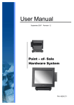
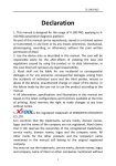
MT-1200
User Manual
2007 January V0.9j
0
Copyright 2007 January
All Rights Reserved
Manual Version 1.0
The information contained in this document is subject to change without notice.
We make no warranty of any kind with regard to this material, including, but not
limited to, the implied warranties of merchantability and fitness for a particular
purpose. We shall not be liable for errors contained herein or for incidental or
consequential damages in connection with the furnishing, performance, or use of
this material.
This document contains proprietary information that is protected by copyright. All
rights are reserved. No part of this document may be photocopied, reproduced or
translated to another language without the prior written consent of the
manufacturer.
TRADEMARK
Intel®, Pentium® and MMX are registered trademarks of Intel® Corporation.
Microsoft® and Windows® are registered trademarks of Microsoft Corporation.
1
Safety
CE MARK
This device complies with the requirements of the EEC directive
89/336/EEC with regard to “Electromagnetic compatibility” and
73/23/EEC “Low Voltage Directive”.
FCC
This device complies with part 15 of the FCC rules. Operation is subject to the
following two conditions:
(1) This device may not cause harmful interference.
(2) This device must accept any interference received, including interference that
may cause undesired operation.
CAUTION ON LITHIUM BATTERIES
There is a danger of explosion if the battery is replaced incorrectly. Replace only
with the same or equivalent type recommended by the manufacturer. Discard
used batteries according to the manufacturer’s instructions.
2
LEGISLATION AND WEEE SYMBOL
2002/96/EC Waste Electrical and Electronic Equipment Directive on the
treatment, collection, recycling and disposal of electric and electronic
devices and their components.
The crossed dustbin symbol on the device means that it should not be disposed of
with other household wastes at the end of its working life. Instead, the device
should be taken to the waste collection centers for activation of the treatment,
collection, recycling and disposal procedure.
To prevent possible harm to the environment or human health from uncontrolled
waste disposal, please separate this from other types of wastes and recycle it
responsibly to promote the sustainable reuse of material resources.
Household users should contact either the retailer where they purchased this
product, or their local government office, for details of where and how they can
take this item for environmentally safe recycling.
Business users should contact their supplier and check the terms and conditions
of the purchase contract.
This product should not be mixed with other commercial wastes for disposal.
3
Safety Statements
The following safety statements will increase the life of the MT-1200. Follow all
precautions and instructions. Except as described in this manual, refer all
servicing to qualified personnel. Do not use damaged power cords, or other
peripherals. Do not use strong solvents such as thinners, benzene, or other
chemicals on or near the surface.
Disconnect the AC power and remove the battery pack (s) before cleaning.
Wipe the MT-1200 using a clean cellulose sponge or chamois cloth
dampened with a solution of nonabrasive detergent and a few drops of
warm water and remove any extra moisture with a dry cloth.
1. DO NOT place or drop objects on top and do not shove any foreign objects
into the MT-1200.
2. DO NOT expose to strong magnetic or electrical fields.
3. DO NOT expose to or use near liquids, rain, or moisture. DO NOT use the
modem during an electrical storm.
4. DO NOT expose to dirty or dusty environments. DO NOT operate during a gas
leak.
5. DO NOT throw batteries in fires as they may explode. Check local codes for
special battery disposal instructions.
4
Table of Contents
1.
2.
3.
4.
5.
6.
Item Checklist ................................................................................................6
System View ..................................................................................................7
2.1. Front View...............................................................................................7
2.2. Side View................................................................................................8
2.2.1. Left Side View...............................................................................8
2.2.2. Right Side View ............................................................................8
2.3. Bottom View............................................................................................9
Basic Operations .........................................................................................10
3.1. Installing the Hand Strap (option)..........................................................10
3.2. Installing the Kick Stand (option)...........................................................10
3.3. Installing the Battery Pack .................................................................... 11
3.4. Connecting the AC Power Adapter ....................................................... 11
3.5. Turning ON the MT-1200 ......................................................................12
3.6. Suspend Mode......................................................................................12
3.7. Using the Stylus Pen.............................................................................12
Drivers Installation .......................................................................................13
4.1. Driver List..............................................................................................13
4.2. Chipset Driver Installation .....................................................................13
4.3. USB Driver Installation..........................................................................15
4.4. VGA Driver Installation..........................................................................18
4.5. Rotation Application Driver Installation..................................................19
4.6. Audio Driver Installation ........................................................................21
4.7. Button Driver Installation.......................................................................22
4.7.1. Software Application ...................................................................23
4.8. Fujitsu Touch Driver Installation ............................................................25
4.9. LAN Driver Installation ..........................................................................27
4.10. PCMCIA/SD Card Reader Driver Installation......................................29
4.11. Wireless LAN Driver Installation..........................................................30
Replacing Components................................................................................32
5.1. Removing the Battery Pack ..................................................................32
5.2. Replacing the Memory Module .............................................................32
5.3. Replacing the HDD ...............................................................................33
Specification.................................................................................................34
5
1. Item Checklist
Take out the system unit from the carton. Remove the unit by carefully clutching
the foam inserts and remove slowly to protect the system. The following contents
should be found in the carton:
a. System
b. Power Cord
c. Power Adapter
d. Stylus Pen
e. Hand Strap (option) and
holders(R&L)
f. Kick Stand (Option)
g. Battery Pack
h. Driver CD
6
2. System View
Refer to the pictures below to identify the components.
2.1. Front View
1
2
3
4
5
6
NO.
1
2
3
4
5
6
Function
Wireless LAN Indicator
Charge Indicator
Drive Activity Indicator
Remark
Blue color – Connected to Access Point
Flash – Searching Access Point
Green Color – Battery Mode
Orange color – Charging Battery
Flash – Low Battery
Flash – Access the storage device
Windows Task Manager
On-Screen Keyboard
Screen Rotation
Defined by software (Refer to Page 26)
Defined by software (Refer to Page 27)
7
2.2. Side View
2.2.1. Left Side View
Lock Port
PCMCIA & SD
HDD or CF
2.2.2. Right Side View
Power Switch
LAN
VGA
USB (2)
Power Input
Headphone
MIC
8
2.3. Bottom View
VESA Holes
Air Vents
Holder
Memory
Compartment
Battery Lock
Battery Pack
9
Battery Lock
3. Basic Operations
This section helps you to start using your MT-1200.
3.1. Installing the Hand Strap (option)
b. Place the strap rings on the holders on
each side and press toward the direction
as shown by the arrow.
a. Place the holders (R&L) in the circled
positions and fasten them with the
screws(2), one on each side .
3.2. Installing the Kick Stand (option)
b. Place the Kick Stand in the holders in
the circled positions.
a. Place the strap-stand holders (R&L) in
the circled positions and stabilized with
screws (2), one on each side.
10
3.3. Installing the Battery Pack
a. Insert the battery pack until it clicks into
place.
b. Slide both Battery Release tabs to the
lock position.
3.4. Connecting the AC Power Adapter
IMPORTANT! Damage may occur if you use a different adapter to power the
MT-1200 or use the MT-1200’s adapter to power other electrical devices. You
may damage both your battery pack(s) and the MT-1200 with a faulty AC-DC
adapter.
(1) Connect this
end of the power
cord to the AC-DC
converter
(3) Insert the
DC power plug
(2) Plug the AC
power cord into an
electrical outlet
11
3.5. Turning ON the MT-1200
a. Press the power button and release at the right side of the system.
3.6. Suspend Mode
The low power modes are designed to save as much electricity as possible by
putting components into a low power consumption mode as often as possible but
also allow full operation on demand. These modes are referred to as “Stand by” or
Suspend-to-RAM and “Hibernation” mode or Suspend-to-Disk (STD).
Recover from suspend mode by pressing the power ON button.
3.7. Using the Stylus Pen
IMPORTANT! DO NOT touch the screen with sharp objects or any other type
of writing instrument. It can damage the screen.
The MT-1200 has a touch-sensitive screen. It allows you to use your stylus pen or finger to
interact with the device. With the MT-1200, you can input data using the full screen area.
12
4. Drivers Installation
4.1. Driver List
Folder/File
File Description
<CD>:\K292.htm
<CD>:\COMMON\INTEL\Chipset
K292 (MT-1200) Series Driver
List
Chipset Driver
<CD>:\COMMON\INTEL\USB20
<CD>:\COMMON\INTEL\VGA\i85x
USB 2.0 Driver
VGA Driver
<CD>:\K292\Rotation
Rotation Application Driver
<CD>:\COMMON\AC97_Codec\Vinyl
Audio Driver
<CD>:\K292\Button_Driver
Button Driver
<CD>:\COMMON\Fujitsu_Touch
Fujitsu Touch Screen Driver
<CD>:\COMMON\Lan_driver\Intel_PRO_1000
10/100/1000Mb LAN Driver
<CD>:\COMMON\PCMCIA\O2Micro_OZ711Mx PCMCIA/SD Card Reader Driver
<CD>:\COMMON\Wireless_LAN\802.11g\Winb IEEE802.11b/g Wireless LAN
ond_W89C35
USB Dongle
-The following procedures are for Windows 2000/XP, other platforms are similar.
4.2. Chipset Driver Installation
a. Click the “infinst_enu_6.3.0.1007” on
the My Computer window.
b. Click the “Next” button on the Setup
window.
13
c. Click the “Yes” button on the Setup
window.
d. Click the “Next” button on the Setup
window.
e. Select “Yes, I want to restart my
computer now” and click the “Finish”
button on the Setup window.
14
4.3. USB Driver Installation
OS Requirements
OS
USB 2.0 requirements
Windows
XP
USB 2.0 drivers are provided in Service Pack 1 (SP1) for Windows
XP, which is available through Windows Update.
Windows
2000
USB 2.0 drivers are available through Windows Update or Service
Pack 4.
Windows
98SE/Me
USB 2.0 drivers are available on the Intel developer site.
Windows
98 (Retail)
Developers and OEMs should contact Orange Ware. For end-users,
if your device does not ship with Windows 98 drivers, contact your
device or system manufacturer. If USB 2.0 drivers are not available,
your device will operate at USB 1.1 speeds
Linux
USB 2.0 support is available in kernel 2.4.19 or later development
kernels, or in the 2.4.19 or later production kernel. More information.
a. Right click My Computer on the
desktop and select “properties”
b. Select “Hardware”Æ”Device Manager”
on system properties.
15
c. Select ”Other Devices” Æ “Universal Serial Bus (USB) Controller” Æ”Properties” on
Device Manager.
d. Select “Device”Æ “Update Driver…”.
e. Click the ”Next” button on the welcome
window.
16
f.
g. Select “Specify a location” and click the
“Next” button on the Locate Driver Files
window.
Select “Search for a suitable…”and
click the “Next” button on the Install
Hardware Device Drivers window.
h. Press “Browse” to select driver and
then click the “OK” button to next page.
i.
j.
k. Finished.
Click the “Finish” button to complete
this process.
17
Click the “Next” button on Driver Files
Search Results window.
4.4. VGA Driver Installation
a. Click the “Win2K_XP” on the My
Computer window.
b. Click the “v14.19.50” on the My
Computer window.
c. Select “win2K_xp141950” on the
v14.19.50 window.
d. Click the “Next” button on the Intel(R)
Chipset Graphics Driver SoftwareInstallShield(R) Wizard window.
e. Click the “Next” button on the Intel(R)
Graphics Media Accelerator Driver
window.
f. Click the “Yes” button on the Intel(R)
Graphics Media Accelerator Driver
window.
18
g. Select “Yes, I want to restart my
computer now” and click the “Finish”
button on the Intel(R) Graphics Media
Accelerator Driver window.
4.5. Rotation Application Driver Installation
a. Select “Disk 1” on the My Computer
window.
b. Select “Setup” on the My Computer
window.
19
d. Click the “Install” button.
c. Click the “Next” button on the
IP1_Rotate Utility – InstallShield
Wizard window.
e. Select “Yes, I want to restart my
computer now” and click the “Finish”
button.
20
4.6. Audio Driver Installation
a. Select “Setup “ on my computer
window.
b. Click the “Next” button on the VIA Vinyl
Audio Codecs Driver Setup Wizard
v6.50d window.
c. Select “I Agree” and click the “Next”
button on the VIA Vinyl Audio Codecs
Driver Setup Wizard v6.50d window.
d. Click the “Next” button.
e. Click the “Next” button.
f. Select “Yes, I want to restart my
computer now” and click the “Finish”
button.
21
4.7. Button Driver Installation
a. Select “Setup” on the My Computer
window.
b. Click the “Next” button on the Button
Driver – InstallShield Wizard window.
c. Click the “Install” button on the Button
Driver – InstallShield Wizard window.
d. Click the “Continue Anyway” button on
the Hardware Installation window.
e. Select “Yes, I want to restart my
computer now” and click the “Finish”
button on the Button Driver –
InstallShield Wizard window.
22
4.7.1. Software Application
F2 – On Screen Keyboard
a. Click the Tablet PC icon and select
“Properties…” on the desktop.
b. Select “Tablet Buttons” and click the
“Change…” button on the Tablet and
Pen Settings window.
c. Select the “Action: Launch an
application” and “Program location”.
Click the “OK” button on the Change
Tablet Button Actions window.
23
F3 – Screen Rotation
a. Click the Tablet PC icon and select
“Properties…” on the desktop.
b. Select “Display” and click the “Change”
button on the Tablet and Pen Settings
window.
c. Select the “screen orientation – 1:
Primary landscape; 2: Primary portrait;
3: [None]; 4: [None]” and click the “OK”
button on the Orientation Sequence
Settings window.
24
Brightness Setup
b. Adjust brightness by moving the cursor
“then click the “Apply” button within the
“Display” category on the Tablet and
Pen Settings window.
a. Click the My Computer icon and select
“Tablet and Pen Settings…” on the
desktop.
4.8. Fujitsu Touch Driver Installation
a. Select Start Æ Control Panel.
b. Select “Touch Panel” on the Control
Panel window.
25
c. Select “Next” Æ on the Touch
Panel-InstallShield Wizard window.
d. Select “Install” on the Touch
Panel-InstallShield Wizard window.
e. Click the “Continue Anyway” button on
the Hardware Installation window.
f. Click the “Finish” button on the Touch
Panel-InstallShield Wizard window.
g. Select Start Æ Control Panel.
h. Select “Touch Panel” on the Control
Panel window.
26
i. Select “Calibration Æ DO NOT click
Use onboard EEPROM to store
calibration result Æ Apply Æ
Calibration Now” on the Touch Panel
Settings.
j. After calibration, select “Update” on the
calibration window.
4.9. LAN Driver Installation
a. Select “Win2K_XP” on the My
Computer window.
b. Select “pro2kxpm” on the My Computer
window.
27
d. Click the “Next” button.
c. Select “I accept the terms in the
license agreement” and click the
“Next” button on the
DriverInstaller-InstallShield Wizard
window.
e. Select “Install Base Driver”.
28
4.10. PCMCIA/SD Card Reader Driver Installation
a. Click the “WinNT4_9X_ME_2K_XP”
icon on the My Computer window.
b. Select “Setup” on the My Computer
window.
c. Click the “Next” button on the
InstallShield Wizard window.
d. Select “Yes, I want to restart my
computer now” and click the “Finish”
button.
29
4.11. Wireless LAN Driver Installation
a. Click the “Win98_ME_2K_XP” icon on
the My Computer window.
b. Click the “v1.0.43.17” icon on the My
Computer window.
c. Click the “w89c35” icon on the My
Computer window.
d. Click the “Next” button on the Winbond
WLAN Installation window.
e. Click the “Next” button.
f. Click the “Next” button.
30
g. Select “Continue Anyway” on the
Hardware Installation window.
h. Click the “OK” button on the “Winbond
Wireless Utility window”.
i. Click the “Finish” button.
31
5. Replacing Components
5.1. Removing the Battery Pack
IMPORTANT! Never attempt to remove the battery pack while the MT-1200 is
turned ON, as this may result in the loss of working data.
a. Slide both battery release tabs to the
unlock position.
b. Pull the battery pack away from the
body.
5.2. Replacing the Memory Module
IMPORTANT! DO NOT touch the gold colored contacts as this can damage
the memory. Ensure that the notches in the memory module line up with the
DIMM slot keys.
a. Remove the screw (1).
b. Use your fingers to push the side to
release the memory module.
32
c. Remove the memory module from the
slot.
5.3. Replacing the HDD
a. Remove the screws (2) that secure the
HDD cover.
b. Slide the HDD towards you.
c. Disconnect the HDD cable carefully.
d. Replace the 1.8” HDD.
33
6. Specification
Model Name
Motherboard
CPU
Core Logic
Memory
Graphic
LCD & Touch
LCD Size
Brightness
Resolution
Touch Type
Storage & Expansion
HDD or Compact Flash
Memory Card Reader
PCMCIA
Input / Output
USB
LAN
Headphone
MIC
Speakers
2nd VGA Output
Button & Indicators
LED
Tablet Buttons
Power & Battery
Power Adapter
Battery
Environmental
EMC & Safety
Operating Temperature
Operating Humidity
MT-1200 (12.1” Tablet PC)
Intel Celeron M or Pentium M @ 800 MHz ~
1.1GHz (BGA Type)
Intel 852GM
SO-DIMM x 1, up to 1 GB
UMA Share Memory up to 64MB
12.1 inch (4:3 Standard)
Up to 190 cd/㎡
1024 x 768 (4:3 Standard)
4-wire resistive type
1.8” HDD Drive Bay or Type II C/F Card
SD Type Card Reader
PC CardBus Type II slot
2 x USB (2.0)
1 (10/100 Mbps)
1
1 x External Jack & 1 x Built-in MIC
1.5 W x 2 (Built-in)
1
3 (1 x Wireless, 1 x Battery, 1 x HDD)
3 (F1 Windows Task Manager, F2 & F3 Defined by
User)
19V / 65W (100V ~ 240V)
Rechargeable Li-ion (4S1P, 14.8V, 2400mAh)
Normal run 2 ~ 3 hours
CE / FCC Class B, cUL
0℃ ~ 35℃ ( 32˚F ~ 95˚F)
20% - 80% (Non-Condensing)
34
Environmental
Thermal Management
IR Rating
Drop Test
Wireless
Dimension (W x H x D)
Net Weight
Operating System
Options
Carry Case
Kick Stand
Hand Strap
Fanless, Passive Cooling
IP53 (Front Bezel)
32 inch high free fall (For C/F card only)
Wi-Fi 802.11 b/g
313 x 235 x 35.7 mm
1.7 kgs (With Battery)
Windows XP-P, XP-embedded
With shoulder strap & stylus pen holder
Removeable kick stand
Removable hand strap
- This specification is subject to change without prior notice.
35