1
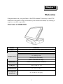
User ’s Manual
Release version 2.0
Preface
About this Manual
Thank you for purchasing our ONE-POS Touch Terminal. This terminal
offers highly enhanced features, with easy connection to various optional
devices for optimal performance. This user manual describes how to setup
and connect your terminal.
Copyright
© Copyright 2007
All rights reserved. This product and related documentation are protected
by copyright and are distributed under licenses restricting their use,
copying, and distribution. No part of this documentation may be
reproduced in any form by any means without prior written authorization
of the manufacturer and its licensors, if any.
Safety notices
Before You Proceed
•
Read the safety notices and the User’s Manual carefully before using the
product.
•
Keep the box and packaging in case the product needs to be shipped in
the future.
•
Follow the product and warning label instructions.
•
Any changes or modifications that do not follow the instructions in this
manual will void this product's warranty.
Power Supply Safety Notes
•
To avoid electric shocks, disconnect the power cord from the electrical
outlet before relocating the system.
•
Make sure the voltage of the power outlet conforms within voltage range
of the terminal. Failure to comply may cause the electric shock or
damage to the terminal. If you are not sure of the electricity voltage that
you are using, consult your local electricity company.
•
To avoid fire or electric shocks, do not overload electric power outlets.
•
Protect the power cord from being walked on or pinched particularly at
plug, convenience receptacles, and the point where they exit from the
apparatus.
i
Preface
Operating Instructions
•
Keep this manual for future reference.
•
Keep this equipment from moisture and dust.
•
Place the equipment on a stable surface before setting it up.
•
If there is any of the following situation arise, notify a qualified service
technician immediately:
¾
The power cord or plug is damaged.
¾
Liquid has been spilt on to the equipment.
¾
The equipment has been dropped and damaged.
¾
The equipment does not function normally.
•
Do not block any ventilation openings to prevent the equipment from
overheat.
•
Do not leave the equipment in a non air-conditioned environment
where the storage temperature may go above 70°C (158°F), as this can
cause damage to the equipment.
Maintenance
•
Gently wipe screen with a clean soft hair lens brush, or a lint-free cloth.
•
Do not apply pressure to the screen while cleaning.
•
Do not spray any liquid directly onto the screen or the casing of the
ONE-POS Terminal.
•
Chemical cleaners have been reported to cause damage on the screen
of the ONE-POS Terminal.
Warning and Attention
•
The technical descriptions and specifications of the equipment are
subject to change without notice.
•
For safety reasons, wear gloves when assembling the product.
Caution
•
Risk of explosion battery is replaced by an incorrect type. Dispose of
used batteries according to the instructions.
ii
Preface
Federal Communications (FCC Statement)
This device complies with FCC Rules Part 15. Operation is subject to the
following two conditions:
•
This device may not cause harmful interference.
•
This device must accept any interference received including
interference that may cause undesirable operation.
This equipment has been tested and found to comply within the limit of a
Class A digital device, pursuant to Part 15 of the FCC Rules. These limits
are designed to provide reasonable protection against harmful interference
in a residential installation. This equipment generates, uses and can radiate
radio frequency energy and, if not installed and used in accordance with
the manufacturer’s instructions, may cause harmful interference to radio
communications. However, there is no guarantee that interference will not
occur in a particular installation. If this equipment does cause harmful
interference to radio or television reception, which can be determined by
switching the equipment on and off, the user is encouraged to try to correct
the interference by one or more of the following measures:
•
Reorient or relocate the interference receiving antenna.
•
Increase the distance of separation between the equipment and
interference receiver.
•
Connect the equipment to a power outlet on a circuit different from
that to which the interference receiver is connected.
•
Consult the dealer or an experienced radio/TV technician for help.
WARNING:
The use of shielded cables for connection of the monitor to the graphics
card is required to assure compliance with FCC regulations. Changes or
modifications to this unit not expressly approved by the party responsible
for compliance could void the user’s authority to operate this equipment.
iii
Content
CHAPTER 1 ................................................................................................1
WELCOME ..................................................................................................1
OVERVIEW OF ONE-POS...................................................................1
FRONT VIEW .......................................................................................2
REAR VIEW .........................................................................................2
OSD CONTROL BUTTONS ....................................................................3
FEATURES ..........................................................................................4
UNPACKING ........................................................................................5
CHAPTER 2 ................................................................................................6
GETTING STARTED...................................................................................6
PRE-INSTALLTION..............................................................................6
DEFAULT SETTING ...............................................................................6
REAR I/O JUMPER SETTING ..................................................................7
MAIN BOARD JUMPER SETTING .............................................................8
LIMITATIONS ........................................................................................9
HARDWARE INSTALLATION ............................................................ 10
INSTALLING THE POWER CORD AND INTERNET CABLE ............................. 10
INSTALLING THE CUSTOMER DISPLAY................................................... 11
INSTALLING THE 2ND LCD DISPLAY (OPTIONAL) .................................... 13
INSTALLING THE MSR ADAPTER BRACKET (OPTIONAL) .......................... 14
INSTALLING THE MSR (OPTIONAL) ....................................................... 15
LCD OPERATION ANGLE ................................................................. 15
INSTALLING AN FILTER AND CLEANING THE FANS..................... 16
HARD DISK DRIVE REPLACEMENT ................................................ 17
APPENDIX ................................................................................................ 18
TECHNICAL INFORMATION .................................................................... 18
SPECIFICATIONS .......................................................................... 18
FREQUENTLY ASKED QUESTIONS (FAQ).................................. 20
iv
Chapter 1
Chapter 1
Welcome
Congratulations on your purchase of this POS terminal. Your easy-to-use POS
terminal is designed to help you enhance your business flexibility by offering a
superior customer experience.
Overview of ONE-POS
Model
ONE-POS
CPU
Intel P4 2.8 GHz / Intel Celeron 2.5 GHz / Intel Celeron D 2.8GHz
Chipset HDD
Intel 852GME + ICH4
2.5” / 3.5 “ x 1
Storage devices
CF memory card
DOM (Disk On Module)
uDOC (USB Disk On Chip)
Serial Port
Total 6 (Touch & MSR I/F included)
USB port
Total 6 (USB Ver. 2.0)
Powered USB
2 (1 x 12V/ 1 x 24V)
DC Output for
peripherals
DC 12V & DC 24V plug
1
Chapter 1 — Welcome
The figures below illustrate the components (including input and output ports)
located at the front and rear views of ONE-POS.
Front View
DESCRIPTION
1
2
3
4
5
6
7
8
9
Slim type CD-ROM
PS/2 Mouse port
CF Card slot
Reset button
Power button
Mic In
USB port x 2
Key lock
LED indicators (From
top to bottom: HDD,
LAN, Power, 5V SB)
Rear View
DESCRIPTION
1
AC in 90 to 264V
full range
2
3
4
5
6
LPT for POS Printer
COM 3
COM 4
COM 1
DC 24V for POS
Printer
DC 12V for 2nd LCD
PS/2 POS K/B port
10/100 Base T LAN
Port
2nd VGA Port
Powered USB 2.0
+12V
Powered USB 2.0
+24V
7
8
9
10
11
12
2
Chapter 1 — Welcome
OSD Control Buttons
ICON
1
Power LED
2
Brightness +
3
Brightness –
4
Speaker +
5
Speaker –
FUNCTION
Red: Standby mode.
Green: System start up.
Press the “Brightness +” and “Brightness –” buttons for
brightness adjustment. The setting will be saved after releasing
the button for 6 seconds.
Press the “Speaker +” and “Speaker –” buttons for volume
adjustment. The setting will be saved after releasing the button
for 6 seconds.
Note:
Press the “Brightness –” and “Speaker +” at the same time to restore the factory default
setting.
3
Chapter 1 — Welcome
Features
This POS terminal comes equipped with the following features:
Fan speed
control
•
The low noise design of the fan speed control for
ONE-POS is ideal for noise-intolerant environment
such as retail store and restaurant, etc.
Patented
HeatPipe
cooling
solution
•
Unique HeatPipe cooling solution is designed for
efficient and effective system cooling in high
temperature environments.
Saving cost of
ownership
•
Modular design provides the owner with the
following benefits: (a) cost effectiveness, (b)
customization flexibility, and (c) easy maintenance.
Compact size/
Aesthetic
design
•
Slimmest in the POS industry standard (24 mm).
This elegant, economic POS system features a sleek,
compact design base that saves counter space and
adds appeal to the service environment.
Dust/waterproof
•
ONE-POS features a highly durable, rigorously
tested design that is reliable and dependable in
rugged environments.
WEPOS/XPE
solution
•
Solution is recommended to be bundled with
embedded solution for high performance and other
added values.
Environment
protection
•
Environmental friendly, RoHS compliant product.
Higher
stability
•
The ONE-POS has a longer overall system MTBF
and provides higher stability during operation.
4
Chapter 1 — Welcome
Unpacking
Before setting up your ONE-POS, check that the package contains the following
items. If any of the items is missing or damaged, contact your vendor
immediately.
ONE-POS Touch
Terminal
Customer Display
(optional)
2nd LCD Customer
Display (optional)
AC Power Cord
Magnetic Stripe Reader (optional)
Filter Cover (optional)
Air Filter (optional)
Accessory Package
1.
Driver CD disc
2.
User’s Manual
3.
Front Door Key
4.
DC24V power cable
5.
P.E. sheet
6.
Spare screws
5
Chapter 2
Chapter 2
Getting Started
This chapter describes how to install the optional accessories on your ONE-POS
Touch Terminal for optimal serviceability.
Pre-installation Notice
Before you start installing your ONE-POS, please read the following notices
carefully.
1.
ONE-POS does not support PCI slot.
2.
Do not plug in or unplug any interior devices, such as memory module or
any function card, when the ATX PSU is powered on.
3.
If using the ONE-POS in a dusty environment, clean the fan and cooler
regularly. Alternatively, protect your system by using a filter, which
should also be replaced at regular intervals.
4.
For installation and compatibility, using the DDR RAM Module from the
original manufacturer is recommended.
5.
The USB device connector is Hot Swap capable. Do not plug in or unplug
any connector except USB devices when the power is on.
6.
The spill proof design of ONE-POS conforms to IP-43 standard.
7.
Do not insert or remove any device or component from the ONE-POS
while the power is on.
Default Setting
Default settings for ONE-POS Touch Terminal serial ports
COM1
COM2
COM3
COM4
COM 5
COM 6
3F8
2F8
3E8
2E8
4F8
4E8
IRQ 4
IRQ 3
IRQ 4
IRQ 3
IRQ 5
IRQ 10
6
Chapter 2 — Getting Started
Preset voltage setting for MSR
1.
The MSR default setting is ISO Track 1 & 2. (For customized track settings,
advise the manufacturer before production.)
2.
In event of any requirement to change the setting of the MSR, run Setting
utility in the driver CD provided in the accessory package.
3.
The normal swiping card speed of the MSR is 10 to 100 cm/sec. (based on
the ISO 7812 standard).
Rear I/O Jumper Setting
J1 COM1/ J3 COM3/ J4 COM4 Voltage Select
Pin 5-6 closed
Normal (COM1 / COM4 default)
Pin 3-4 closed
+5V (COM3 default for RS232 Customer Display)
Pin 1-2 closed
+12V
Note: Please refer to page 17 for HDD bracket release.
7
Chapter 2 — Getting Started
Main Board Jumper Setting
J4 COM5 Voltage Select
Pin 1-2 closed
+5V (default)
Pin 2-3 closed
+12V
J5 COM5 Function Select
Pin 1-2 closed
Normal (default)
Pin 2-3 closed
+5V or +12V for RS232 MSR or other RS232 device
JP1 CMOS Clear
Jumper Off
Default
Jumper On
CMOS clear
8
Chapter 2 — Getting Started
Limitations
Connector with
Voltage Output
COM 1 for extension
interface (9th PIN of DB-9)
COM 2 for Touch Panel
interface
COM 3 for extension
interface (9th PIN of DB-9)
COM 4 for extension
interface (9th PIN of DB-9)
COM 5 for extension
interface
COM 6 for Cash Drawer
driving
DC 12V Powered USB for
peripherals
DC 24V Powered USB for
peripherals
*2nd LCD Monitor Power
Connector (DC Plug)
*DC 24V Printer Power
Connector (Hosiden
3PIN)
Location
Average current
Pack current
Bottom side (On
Interface Board)
DC 5V / 0.5A,
DC 12V / 0.5A
DC 5V / 0.8A,
DC 12V / 0.5A
LCD Panel Side
DC 5V / 0.3A
DC 5V / 0.5A
Bottom side (On
Interface Board)
Bottom side (On
Interface Board)
DC 5V / 0.5A,
DC 12V / 0.5A
DC 5V / 0.5A,
DC 12V / 0.5A
DC 5V / 0.5A,
DC 12V / 0.5A
DC 12V / 1A
DC 24V / 1A
DC 5V / 0.8A,
DC 12V / 0.5A
DC 5V / 0.8A,
DC 12V / 0.5A
DC 5V / 0.8A,
DC 12V / 0.5A
DC 12V / 1A,
DC 24V / 1A
DC 12V / 1.5A
DC 12V / 2.5A
DC 24V/ 1.5A
DC 24V / 2A
DC 12V / 1.5A
DC 12V / 2.5A
DC 24V/ 1.5A
DC 24V / 2A
LCD Panel Side
External connector
Bottom side (On
Interface Board)
Bottom side (On
Interface Board)
Bottom side (On
Interface Board)
Bottom side (On
Interface Board)
Note:
•
The current loading for each COM Port should not exceed DC 5V/3A + DC 12V/2A.
•
DC 12V /24V powered USB should not be used with 12V DC plug and 24V Hosiden
at the same time.
•
When the 2nd Display uses 12V DC plug, the thermal printer can NOT use the 24V
Hosiden simultaneously.
9
Chapter 2 — Getting Started
Hardware Installation
Installing the Power cord and Internet cable
To install the power cord and Internet cable, do the following:
1.
Release the three screws (one M3 screw from the top side, two
thumbscrews on both sides) securing to the base cover.
2.
Connect the Internet RJ 45 cable and the power cord and pass the cables
through the hole on the bottom of the base cover as shown.
RJ 45
connector
Power cord
connector
10
Chapter 2 — Getting Started
3.
Replace the base cover with the three screws removed in step 1.
Installing the Customer Display
1.
Remove the two M3 screws securing to the stand cover.
11
Chapter 2 — Getting Started
2.
Assemble the Customer Display with the cover stand and plug the RS232
connector of the Customer Display into the COM3 port as shown.
3.
Install the Customer Display and the cover stand in place with three M3
screws as indicated in the figure below.
12
Chapter 2 — Getting Started
Installing the 2nd LCD Display (optional)
To install the 2nd display onto the ONE-POS Terminal, do the following:
1.
Remove the base cover and stand cover.
2.
a: Connect one end of the DB 15 cable to the VGA port and pass the cable
through the hole on the bottom of the base cover as shown.
b: Connect one end of the DC 12V adapter cable and allow the other end of
the cable pass through the hole on the 2nd Display cover stand.
2nd Display
cover stand
DB 15 cable
DC 12V adapter
cable
3.
Replace the base cover. Affix the 2nd Display cover stand to the base with
three M3 screws. Next, connect the other end of the DC 12V adapter cable
and the DB 15 cable to the 2nd Display.
13
Chapter 2 — Getting Started
4.
Install the 2nd Display and lock it to the stand with four M3 screws.
Installing the MSR Adapter Bracket (optional)
An adapter bracket will be required when installing the MSR module on the
ONE-POS Terminal.
To install the extension bracket, do the following:
1.
Attach the MSR adapter bracket onto the right side of the Terminal
and fix it with two long screws and two short screws as shown.
Long screws
2.
Short screws
After the adapter bracket has been attached, you can start installing
the MSR module to the Terminal. See the following sections for
detailed instructions on the installation procedures.
14
Chapter 2 — Getting Started
Installing the MSR (optional)
To install the MSR onto the Terminal, do the following:
1.
Attach the MSR device jack to the MSR socket on the right side of the
adapter bracket.
2.
Affix MSR wires firmly to the slots on the side of the Terminal.
3.
Attach the MSR device to the screw head on the side of the Terminal.
4.
Lock the MSR securely on the LCD display with one M3 screw.
LCD Operating Angle
The LCD display is equipped with an adjustable hinge of 0° to 90°.
15
Chapter 2 — Getting Started
Installing a Filter and Cleaning the Fans
To install a filter and access the fans for cleaning, do the following:
1.
Place the supplied filter over the bottom vent on the fan cover at the
rear of the ONE-POS Terminal as shown (A).
2.
Pinch both sides of the fan cover and lift off to gain access to the fans
(B).
3.
Replace the fan cover once you have cleaned the fans.
Note:
•
If using the ONE-POS in a dusty environment, clean the fan and cooler regularly.
Alternatively, protect your system by using a filter, which should also be replaced at
regular intervals.
16
Appendix — Getting Started
Hard Disk Drive Replacement
To replace the hard disk drive, do the following:
1.
From the bottom side of the ONE-POS Terminal, release the
thumbscrew (A) and slide the HDD bracket down in the direction of
arrow (B).
2.
Pull out the HDD bracket and disconnect the power and data
connectors from the hard disk drive as shown (C).
3.
Remove the four screws fixing the hard disk drive (D).
4.
Replace the hard disk drive with a new one. Then follow the abovementioned steps in reverse to finish the replacement.
Note:
1.
The external IDE connectors (F) & (G), which are covered by the IDE cover (E), allow
you to connect with an external IDE device.
2.
The external IDE device must be set to slave and CANNOT coexist with CF both.
Ap pendi x
17
Appendix — Technical Information
Technical Information
Specifications
ITEM
SPECIFICATION
Model Name
ONE-POS All in One Touch POS System
Processor
Supports Intel P4 CPU up to 2.8GHz or Intel Celeron CPU
up to 2.5GHz or Intel Celeron D CPU 2.8GHz
Memory
184-pin DDR RAM *2, up to 2GB (DDR266/333)
System Core
Chipset
North Bridge: Intel 852GME
South Bridge: Intel ICH4
BIOS
Award BIOS with enhanced ACPI 1.0
PnP/APM/DMI/ESCD/PCI bus 2.1/ On Now/ DRAM ECC
AGP 3D
Graphics
Intel AGP8X graphics core, share memory from 8MB up to
32 MB support DVMT (16MB Default)
Dual VGA output (Dual-view on North Bridge Chips)
Supports 3D/2D graphics accelerator
NT 4.0/5.0, Windows 95/98/2000/XP utility
APM/ACPI 1.0
DirectX 9.0, VPE, MPEG2
Parallel Port
One LPT port (SPP/EPP/ECP), IRQ and address selectable
by BIOS setup
Serial Port
Total 6 COM ports on board, IRQ selectable by BIOS setup
Output on 9th pin by jumper selector. Each voltage output
with poly switch protector.
USB
Total 6 USB ports (USB 2.0) support
Two USB ports located on the front panel
Two USB ports located on the rear panel for powered USB
One USB port located on the right side panel for MSR
One internal USB port located on the motherboard for
uDOC
Enhance PCI
IDE
On board PCI bus master IDE1/2, support Ultra
DMA33/66/100
18
Appendix — Technical Information
ITEM
SPECIFICATION
Thermal
Solution
One heat-sink with Fan (Base on Fan Speed Control
technology) for CPU Chip. One heat-sink for N/B Chip.
Compact Flash
Card
One bootable compact flash card socket (Type I/II)
Cash Drawer
Port
One cash drawer port with status sensor. (EPSON ESC Pin
define)
System Power
ATX 250W Internal Power Supply
AC Power
Source
AC 90 to 264V Full Range.
System Trigger
Control
System front side tact switch (ATX Trigger) below the LCD
display with bottom.
Ethernet Port
(10/100 Mbps
Auto)
Intel PRO 100 Ethernet chip on board
Intel Ethernet chips on board (10/100 base- T, Gigabyte
extendible)
ACPI/NT 4.0/5.0 (NDIS5)
Remote boot ROM for NT 4.0
Enable or disable by BIOS setup
Audio
ALC 655 AC97 CODEC on board
Keyboard
PS/2
Mouse
PS/2
Wall Mount
VESA standard 100mm
System Size
355mm (L) x 350mm (W) x 340mm (H), min. height when
folded: 160mm
S/W
Compatibility
DOS/OS2 V2.1/SCO XENIX: V2.3.2/SCO UNIX
V3.2/NOVELL/WIN 3.1/95/98/2000/XP/NT4.0/XPE/WEPOS
Operation
Temp.
0°C to 40°C
Storage Temp.
-25°C to 70°C
Optional
Device
ISO Trick 1/2/3 Magnetic Stripe Reader
Smart Card Reader
20 column * 2 lines VFD Customer Display
19
Appendix — Technical Information
ITEM
SPECIFICATION
Optical Finger Print Sensor
10.4” or 12.1” LCD Customer Display
32 Keys Programmable POS Keyboard
Note:
Specifications are subject to change without notice.
Frequently Asked Questions (FAQ)
Question 1: Why does the system appear unstable after updating BIOS?
Answer: Load optimized defaults (or load SETUP Default) after flashing
BIOS. If the system remains unstable, clear CMOS to solve the
problem.
Question 2: How do I clear CMOS?
Answer: To clear CMOS, do the following:
1.
Turn off power and pull out the power cord.
2.
Insert the jumper cap to clear CMOS PIN and remove the
jumper cap from clear CMOS PIN.
3.
Switch on the power again.
4.
Press Delete to enter CMOS setting and load optimized
defaults.
5.
Save changes and reboot the system.
Question 3: How to use Boot Menu?
Answer: To use the Boot Menu, do the following:
1.
Press F9 to enter the Boot Menu.
2.
Select the Boot device from the Boot Menu.
20