1
Section 3 Operation
Installation and Operation Manual
X-PR-LR-056-PD-eng
Part Number 541B171AAG
February, 2012
Brooks® LR-056
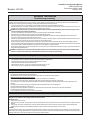
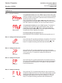
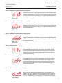
Menu 6 - Activation of the exceeding message
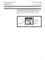
After confirming “HILo” by pushing both buttons, the alarm for exceeding
the range of the display can be activated. The status can be set on “on” or
“off”. To complete the setting push both buttons simultaneously.
High / Low
Pressure
Note: Please note that the exceeding message “HI” or “Lo”, if turned on,
appears in change with the contact message (special menu 5 ocon).
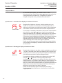
Menu 7 - Setting the switch-on point for switch point 1
After confirming “S1on” by pushing both buttons, the value can be set at
which switching point 1 is activated. To complete the setting push both
buttons simultaneously.
Set Point 1 on
Note: For further information refer to the figures in menu “11”.
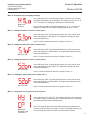
Menu 8 - Setting the switch-off point for switch point 1
After confirming “S1oF” by pushing both buttons, the value can be set at
which switching point 1 is deactivated. To complete the setting push both
buttons simultaneously.
Set Point 1 oF
Note: For further information refer to the figures in menu “11”.
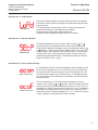
Menu 9 - Setting the switch-on point for switch point 2
After confirming “S2on” by pushing both buttons, the value can be set at
which switching point 2 is activated. To complete the setting push both
buttons simultaneously.
Set Point 2 on
Note: For further information refer to the figures in menu “11”.
Menu 10 - Setting the switch-off point for switch point 2
After confirming “S2oF” by pushing both buttons, the value can be set at
which switching point 2 is deactivated. To complete the setting push both
buttons simultaneously.
Set Point 2 oF
Note: For further information refer to the figures in menu “11”.
Menu 11 - Hysteresis and compare mode of set point 1
After confirming “HY1” resp.”CP 1”by pushing both buttons, the hysteresis
or compare modes for switching point 1 can be switched over. To complete
the setting push both buttons simultaneously.
Hysteresis /
Compare mode
(Set Point 1)
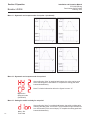
Note: The following figures show the difference between hysteresis and
compare mode as well as its inverting. To invert the respective modes, you
must exchange the values for switch-on point an switch-off point.
3-5