1
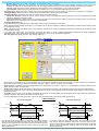
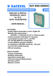
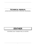
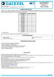
PROSOFT
User Manual
Prosoft User Manual
Phone: +1 561 779 5660 - e-mail:[email protected] www.datexel.com
3.05 VERSION
GENERAL DESCRIPTION
PROSOFT is a software developed by Datexel srl, running under the operative system Windows ® and designed to program and visualize the
measure of the converters and transmitters programmable by PC. To operate with PROSOFT it is necessary to use the programming interface
(PRODAT) between the P.C. and the device; refer to the following table to use the right interface and device.
DEVICE / INTERFACE
PRODAT-04 / PRODAT USB
DAT 1010
P
P
P
P
P
P
P
P
P
P
P
P
P
P
P
P
P
P
P
P
P
P
P
DAT 1015
DAT 1070
DAT 1075
DAT 1060
DAT 1061
DAT 1065
DAT 1066
DAT 2015
DAT 2115
DAT 2115/SEL
DAT 4035
DAT 4135
DAT 4135/SEL
DAT 4135 AC
DAT 4235
DAT 4510
DAT 4520
DAT 1010 IS
DAT 1015 IS
DAT 1065 IS
DAT 2015 IS
DAT 4035 IS
CVPR-03 (*)
PRODAT IS
M ANDATORY
M ANDATORY
M ANDATORY
M ANDATORY
M ANDATORY
P
DAT 4235 IS
P = usable interface.
To connect devices and interfaces refer to the relative technical Data-sheets .
(*) NOTE: when requested, this protection cable must be used jointly to PRODAT.
SYSTEM REQUIREMENTS
Windows® 98 / 2000 / NT / ME / XP/ Vista / Win 7
2 MB
Operative System
Available Hard Disk space
PROCEDURE OF INSTALLATION
Close eventual active or background applications .
● Insert the CD-ROM of installation into the driver.
● Wait for the Autorun window opening (**) .
● Click the button Tools.
● Click the button “download” in the section PROSOFT V305.
(**) If the Autorun function is disabled, open the CD-ROM and execute the installation file using the path:
<CD Driver>:/doc/prosoft/prosoft305_setup.exe.
● Follow the Installation Wizard.
OPEN PROSOFT
Connect the serial port to the interface PRODAT (***).
Connect the PRODAT to the device on programming as shown on its technical data-sheet. Power on the device.
(***) Note for PRODAT USB: verify the serial port number assigned to it by Windows ® during its installation ( go to Control Panel – System and
Maintenance - Device Manager), than set this COM number in the sub-menu “Communication Ports” of PROSOFT.
Be sure that the communication port selected is not used by other applications or programs.
Execute the program using the path “Start \ Programs \ ProSoft \ ProSoft”.
PROSOFT tries to establish the connection with the device with 5 attempts maximum; if this operation ends correctly, a bar will be filled; during
this phase, will be read all the programming data of the device; then will be opened the main form of the program.
When activated, PROSOFT allows the user to program the device ( “Programming” mode) or to visualize its measure (“Measure” mode).
●
MAIN FORM
MENU COMMANDS & TOOL BAR
- File : contains the basic operations to open and save the configuration files.
Open
Save
allows the user to open a configuration file previously saved with the format (*.D70).
allows the user to save the configuration in use overwriting the existing file.
Save as: allows the user to save the configuration in use creating a new file or overwriting an existing file.
Exit
allows the user to exit from PROSOFT.
- Options : contains the sub-menus:
Communication Ports: shows the configuration of all COM ports available on the P.C. up to the COM port number 16.
Language : allows the user to set up the language of PROSOFT.
- Action : contains the sub-menus:
Start
allows the user to start the functions of programming and measure.
Stop
allows the user to stop the function of measure.
- Display Measure
Full screen
increases the dimensions of the measure form inside which will be shown the measure provided by the device (this
command is enabled only if PROSOFT is on “Measure” mode ).
- ? : Help on line: allows the user to enter into the help of PROSOFT.
- Info: visualizes information about PROSOFT.
- (Tx <-> Rx)
allows to recover the connection between device and P.C. in the case it has been interrupted ( due to interruption of the serial
connections, interruption of the power supply, etc..).
- (Wizard) starts a wizard that simplifies the use of PROSOFT.
FUNCTIONS
Figure 1 – “Programming “ mode
1
4
5
2
6
7
8
9
10
11
3
14
15
16
12
13
18
17
Figure 2 – “Measure “ mode
19
29
28
30
1) Device: identifies the typology of the model connected when the user starts PROSOFT .
2) Programming Information: visualizes the programming data of the device; this field is uploaded after each programming .
3) Mode.
“Programming mode” (figure 1): sets up PROSOFT to the Programming mode. In this mode the user can set the parameters of
configuration; click the “START” button (blue) to send the programming data to the device.
4) Input Type: allows the user to select the input sensor (ex: thermocouple) and its eventual typology (ex. type “K”).
5) Input Range: allows the user to set the minimum and maximum values of the input range.
6) Input Options: field where the user can set the options of the input range in function of the sensor selected.
7) Custom ( figures 3 and 4 ).
If the input sensor is not included in the default input type list of PROSOFT, it is possible to perform a linearisation per points ; such
method is defined “Custom”.
To set the parameters follow next operations.
Go to “Programming mode” - “Input type” (4 - figure 1) and select the input sensor without specify its typology in case of
thermocouple or RTD. Moreover in case of RTD or resistance specify the number of wires; in case of thermocouple select if it is
with internal or external cold junction compensation.
Click the check-box “Custom” (*)(7 – figure 1); will be opened the form “Custom – Physical Function ”(figure 3).
(*) If the check-box is already enabled and the user has to modify data, it is necessary click to disable the check-box and click again
to enter into the form.
Figure 3 – custom linearisation : form physical function
21
20
21) Number of points: allows the user to set the number of points necessary to perform the linearisation; in function of this number
will be selected the rows of the table. The maximum number of points selectable depends on the typology of the device connected.
21)Table ”Physical Function” : the table is constituted of two columns; write in the left column (linearised value) the physical
value of input (°C, ohm, ..); write in the right column (value to be linearised ) the correspondent electrical value provided from the
sensor (mV for TC, ohm for RTD,...) connected on its input. The values must be written in the increasing order, while the decimal
point (point or comma) must be the same of that one used by Windows ®. If the input sensor is not a thermocouple with internal cold
junction compensation, click the button OK to confirm the values inserted and go back to the ” Programming mode”.
If the input sensor is a thermocouple with internal cold junction compensation, click the tab “Junction compensation” to open the
relative form (figure 4).
Figure 4 – custom linearisation : form Junction compensation
23
22
22) Number of points: allows the user to set the number of points necessary to define the junction compensation; in function of
this number will be selected the rows of the table (limits: -20÷70 °C or -4÷158 °F). The maximum number of points selectable is 6.
23) Table “Junction compensation”: the table is constituted of two columns; write in the column “Temp IN” (linearised value) the
physical value of input (°C) ; write in the column “mV OUT” (value to be linearised ) the correspondent electrical value provided from
the sensor (mV) . At the end of the operation click the button OK to confirm the values inserted and go back to the ” Programming
mode”. Continue with the standard programming .
8) Filter: allows the user to filter, via software, small variations of the input signal.
9) Linearisation: allows the user to linearise, via software, the output characteristics of Thermocouples and RTD; if this function is not
enabled, the output of the device will be linear with the voltage (Thermocouples) or the resistance (RTDs) provided from the sensor.
10) CJC: allows the user to enable / disable the internal Cold Junction Compensation ( only for Thermocouples).
11) Temp Unit: allows the user to select the unit of measure (°C or °F) for Thermocouples and RTD sensors.
12) Output Type: allows the user to set the type of output signal as current ( for transmitter and converters ) or voltage ( for converters).
13) Output Range: allows the user to set the minimum and maximum values of the output range.
14) Output Options: field where the user can set the options of the output range .
15) Direct / Reverse: allows the user to set the variation of the output signal as directly (direct) or inversely (reverse) proportional
versus the variation of the input signal.
16) Sensor Burn-out : allows the user to force the input signal over the maximum (High) or under the minimum value (Low) when the
input sensor is not connected or its connection is interrupted.
17) Output Regulators (*)
It is possible to correct eventual errors of the output measure using the following commands:
Zero : adjusts the Zero (begin scale value) ± 5% maximum of the span of measure ( difference between the maximum and minimum value
of the measure range).
Span : adjusts the Span (full scale value) ± 5% maximum of the span of measure ( difference between the maximum and minimum value
of the measure range).
(*) To adjust the output value it is necessary to program the device; in case of several adjustments, PROSOFT will make progressive
regulations of the output value referring to the last programming value read ( value already adjusted).
18) Trips (figure 5): recalls the form “Trip settings” (figure 5).
Figura 5 – Trip settings
25
24
27
26
By this form it is possible to set up the trips alarm only for the devices where this function is provided ( ex. DAT 4235 IS); for the devices
where this function is not provided, the commands Trips (18 – figure 1 and 28 – figure 2 ) are not visible.
24) Input Type: recalls the input range programmed in the “Programming” mode (5 – figure 1 ); is not possible to modify the data into the
fields “Min” and “Max” of this section.
25-26) Trips 1 and 2 : allows the user to set the typology of work for the trip ( see “Trip operation” section), the Trip Level expressed as
the same unit of measure of the input range (fields Trip) and the value of the Hysteresis Level expressed as percentage of the input range
(fields Hysteresis).
27) Delay: allows the user to set the delay, expressed as seconds, for the energizing and de-energizing of the relays when the relative trip
changes condition. This value is the same for both the trips .
For the characteristic of work of the trips, refer to the technical data-sheet of the device under programming.
TRIP OPERATION
HIGH ALARM THRESHOLD
LOW ALARM THRESHOLD
Trip level + hyst.
Trip level
Trip level - hyst.
Trip level
T(delay)
T(delay)
Active relay
For the high alarm the relay goes on when the input signal is higher
than the trip level and after the delay time. The relay goes off only
when the input signal is lower than the trip level minus the hysteresis
value or when reaches the minimum value of the input scale and
after the delay time.
T(delay)
T(delay)
Active relay
For the low alarm the relay goes on when the input signal is lower
than the trip level and after the delay time. The relay goes off only
when the input signal is higher than the trip level plus the hysteresis
value or when reaches the maximum value of the input scale and
after the delay time.
3) Mode.
“Measure” mode (figure 2): visualizes, in real time, the input value measured in the engineering unit previously programmed (°C,°F, etc.)
and the corresponding measure in mA or V provided from the device on its output.
To enable this operation, click the button “START” (yellow); to stop it click the button “STOP” (yellow).
19) Communication Activity's Led .
State
Fix red: communication with the device not enable.
Blinking: communication activity in progress; during this operation it is recommended to don't disconnect the serial cable.
28) Trip condition's LED.
State
Red: active alarm.
Green: not active alarm.
Yellow: changing of the alarm state in progress (delay).To set parameters, see point 18 (Trips).
29) Input / Output Measure Display.
In the input measure Display is shown a calculated value in function of the programmed range; in the output Measure Display is shown the
real output value provided from the device.
30) Measure's condition filling bar.
The grade of filling of this bar shows the level reached from the generated output value in function of the programmed values; if this value
is over or down the programmed limits or the device is on Burn-out condition, the rectangles placed beside this bar will become red .
DAMPING
Time value expressed in step of 0.3 seconds that allows the user to slow down the response time of the device.
If the value is 0 this function is disable and the device is set with its standard response time
ERROR MESSAGES
- “It's impossible communicate with the device”.
This message appears when one or more of the following events happen:
● Serial or USB cable not correctly connected.
● Drivers of the interface ( only PRODAT USB) not installed or not correctly installed.
● Device not powered.
● Device's power supply value lower than the minimum specification limits (see technical data-sheet of the device ).
● Device's power supply polarity reversed.
● Cable between interface and device not correctly connected.
● Noise on serial line.
● PRODAT connected to a COM port different of that one selected .
After the resolution of the problem, click the button “Retry”. In the case of is not possible to find the fault, click the button “Cancel”; the device
will result not connected to PC. To recover the communication, click the button “TxRx” into Tool bar.
- “"No communication port is available"”.
Communicates to the user that is not possible to communicate with the device because there aren't serial port available on the PC.
Causes of this error could be :
● No serial ports installed on the PC.
● Other programs or peripherals (ex: mouse) are using all the serial ports available.
- “"Out of Range : ".
Communicates to the user that the maximum and minimum limits are over the specification limits (see technical data-sheet of the device ).
- “The maximum value must be higher than the minimum”.
Communicates to the user that has been written a minimum value higher than the maximum values in the field Input Range and / or Output
Range
- "Invalid format"
Communicates to the user that has been written parameters in not correct format (control decimal point) or in decreasing order.
- “Type mismatch”.
Appears in several cases, for example when the user tries to program the device and there are some fields empty or the data are not correct;
in this case will be closed the program and the user will have to recover the communication with the device .
- "Points number must be included between 2 and ".
Communicates to the user that has been written in the forms of the custom linearisation a number of point higher than the maximum allowed.
- “Invalid file format”.
Appears when the user tries to open a file with format different of (.D70).
- "Illegal Span: if you continue , the measure could be influenced by noise. Do you want to continue ?"
Notices the user that the range written in the field Input Range and / or Output Range is equal to the minimum span allowed.
- "Reading error or device not compatible with this ProSoft version"
Appears when the user tries to communicate whit a device not included into the table device/interface.
- "The Burn-out level coincides with the 'Zero level'”
Notices the user that have been setted a Low sensor Burn-Out with output programmed as 0÷20 mA or 0÷10V.
ED.05.12 REV.00
Datexel s.r.l. reserves its rights to modify totally or in part the characteristics of its products without notice at any time .