1
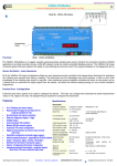
DATESOFT
Version 2
User Guide
Datasoft User Manual
Tel: +1 561 779 5660 - e-mail:[email protected] - www.datexel.com
GENERAL DESCRIPTION
DATESOFT is a software developed by Datexel srl, running under the operative system Windows ® designed to program and visualize the
measure of the converters programmable by PC listed in the table below. To operate with DATESOFT it is necessary to use the programming
interface (PRODAT) between the P.C. and the device on programming.
DEVICE/INTERFACE
PRODAT-04 / PRODAT USB
DAT 4530
P
P
P
P
P
P
P
P
P
P
P
P
P
P
P
P
P
DAT 4531 A
DAT 4531 B
DAT 4531 C
DAT 4531 D
DAT 4532 A
DAT 4532 B
DAT 4532 C
DAT 4532 D
DAT 4631 A
DAT 4631 B
DAT 4631 C
DAT 4631 D
DAT 4632 D
DAT 4535
DAT 4540
P = usable interface.
DAT 1135
To connect devices and interface refer to the relative technical Data-sheets .
SYSTEM REQUIREMENTS
Windows® XP / Vista / 7 / 8
2 MB
Operative System
Available Hard Disk space
PROCEDURE OF INSTALLATION
Close eventual active or background applications .
Insert the installation CD-ROM into the driver.
● Wait for the Autorun' s window opening .
open the CD-ROM and execute the installation file using the path:
<CD Driver>:file:///<CD Driver>file://D:/eng/tools/software.html
Click on the button “download”.
● Follow the Installation Wizard.
●
●
OPEN DATESOFT
Connect the programming interface PRODAT to the Com port of the PC.
If the programming interface is the PRODAT USB, verify the Com port number assigned to it by Windows ® during its installation ( go to Control
Panel – System and Maintenance - Device Manager).
Connect the PRODAT to the device by the proper cable as shown in the device's data-sheet.
Power on the device.
Be sure that the Com port selected is not used by other applications or programs.
Execute the program at the path “Start \ Programs \ DATESOFT \ DATESOFT”.
When the software is running, the default window appears ( Picture 1).
Set the number of the Com port (1, Picture 1).
Click on the button “Open Com”(2, Picture 1); the program tries to communicate with the device. If the communication ends correctly, the led
of communication becomes green. (3, Picture 1) .
When active, DATESOFT allows the user to:
● program the device by PC(Program mode)
● visualize the measure (“Measure” mode) ;
● control the dip-switches settings and configure them with device connected (Switch mode).
● view how to set the dip-switches with device not connected (Switch Wizard)
Pag. 1 of 20
Picture 1 – Toolbar, communication active
1
2
3
4
5
6
7
8
9 10 11
MENU BAR (Picture 1)
- Menu “File” : not active.
- Menu “View” : contains the commands to recall the mode windows of the software.
Measure : allows to recall the Measure mode window.
Program: allows to recall the Program mode window.
Switch: allows to recall the Switch mode window.
- Menu “Action” : contains the following action commands.
Program → read: allows the user to read the configuration data from the device in the “Program” mode.
Program → write: allows the user to send the configuration data to the device in the “Program” mode.
Measure → start: starts the reading of the data measured from the device in the “Measure” mode.
Measure → stop: stops the reading of the data measured from the device in the “Measure” mode.
- Menu “?” : contains the information about DATESOFT and a direct link to the DATEXEL website.
- Command “Exit” : allows to exit DATESOFT.
TOOLBAR (Picture 1)
- Button “Com” (1): allows to set the number of the Com port (port numbers available from 1 to 16).
- Button “Open/Close Com”(2): enables (Open Com) or stops (Close Com) the communication with the device.
- Filling bar and led of communication (3) the filling bar shows the progress of the data transmission from DATESOFT to
the device. The red led shows the data transmission in progress, the green led the end of it.
In the “Measure mode”, when the data transmission is continuous, the led blinks from red to green.
- Label “Version”(4): shows the type and version of the device connected.
- Button “View measure”(5): allows to move to the “Measure” mode window (if it is still open) or to open it.
- Button “View program”(6): allows to move to the “Program” mode window (if it is still open) or to open it.
- Button “View switch”(7): allows to move to the “Switch” mode window (if it is still open) or to open it.
- Button “Read”(8): when the “Program” and/or the “Switch” mode windows are active allows to read the programming
data from the device.
- Button “Write”(9): when the “Program” mode window is active allows to send the new programming data to the device.
- Button “Start / Stop”(10): starts or stops the reading of the data measured from the device in the “Measure” mode.
- Button “Language”(11): allows to set the language ( English or Italian) of DATESOFT.
Pag. 2 of 20
MEASURE MODE (Picture 2)
Picture 2 – Measure Mode active
12
13
14
15
The “Measure” mode window allows to visualize, in real time, the input and output measures.
This window appears clicking on the button “View measure” (5-Picture 1) on the Toolbar and works only if the communication with
the device has been enabled (button Open Com, 2-Picture 1) .
To start the measure, click on the button “Start/Stop” (10-Picture 1) on the Toolbar; to stop the measure click on the same button.
It is possible to visualize the measures either if the device has been programmed by PC or by dip switches.
Screenshot
- Button “ I> ” (10- Picture 1): Start the measure process. The device will send the measured data to the software. Do not
disconnect the serial cable during this operation.
- Button “ II ” (10- Picture 1): Stop the measure process.
- Sections “Input A” (12) and “Input B” (14): visualize the input measures of each channel expressed in the engineering unit
programmed; the input type and range programmed are shown on the bottom left side of the each section.
- Sections “Output A” (13) and “Output B” (15): visualize the output measures of each channel expressed in the engineering
unit programmed ; the output type range programmed are shown on the bottom left side of the each section.
The sections 12, 13, 14 and 15 will be visualized in function of the type of device connected:
- DAT 4535 and series DAT 4531: visualization of the sections 12 and 13.
- Series DAT 4532: visualization of the sections 12, 13, 14 and 15.
- Series DAT 4631: visualization of the sections 12, 13 and 15.
- DAT4530: visualization of the sections 12, 13 and 15. The section 14 is updated as section “Trips” (Picture 2A).
- DAT4540: visualization of the sections 12 and 13.The section 14 is updated as section “Trips” (Picture 2B).
MEASURE MODE – SECTION TRIPS (Pictures 2A and 2B)
Pictures 2A/2B – Section “Trips” active for DAT4530 (Picture 2A) and DAT4540 (Picture 2B)
Picture 2A
Picture 2B
16
17
18
Section “Trips” Screen-shot:
- Section “Trip A (Pictures 2A and 2B - 16) ”:the parameters H and L shown the two threshold values (high – H and low - L) set
in the Program mode; the parameter MAX or MIN shows the type set for the threshold; the parameter “Delay” shows the delay
time set for the threshold.
- Section “Trip B (Picture 2B - 17) ”:the parameters H and L shown the two threshold values (high – H and low - L) set in the
Program mode; the parameter MAX or MIN shows the type set for the threshold; the parameter “Delay” shows the delay time set
for the threshold.
For the sections 16 and 17 the LED changes colour as following in function of the state of the thresholds:
- Green: threshold not active.
- Red: threshold active.
- Yellow: threshold in condition of transition from active to not active and vice-versa ; the colour yellow is present for the time set
in the parameter “Delay”.
Section “Alarm (Picture 2A and 2B - 18) ”: this parameter shows the type of Fault alarm sensor. It is not active for DAT4530.
Pag. 3 of 20
PROGRAM MODE
By this window it is possible to set the parameters of configuration and to save them in Eeprom.
The input and output parameters programmed by this window will be active only if all of the dip-switches relative to the input
types are in OFF position; vice-versa, the options parameters will be active either in case of programming by PC or dipswitches.
The visualization of the programmable parameters depends on the type of device connected.
Notes:
1) it is possible to change the data in this window only if the communication has been enabled (“Open Com” - 2, Picture 1).
2) the parameters programmed are saved in Eeprom also if the device has been configured by dip-switches.
Picture 3 – Program Mode – DAT 4530
21
23
19
20
24
25
22
DAT 4530 (Picture 3)
Screenshot
- Section “Input” (19): allows to select the input type and the zero and full scale values of the input range. The
specification limits admitted for each input type selected are shown on the bottom side of the section.
The parameter °C/°F allows the user to set the Program window also in °F for the temperature sensors.
Note: at the first connection the measures are always shown as °C.
- Sections “Output ” (20) : allows to select the output type and the minimum and maximum values of the output range for
each output. The specification limits admitted for each output selected are shown on the bottom side of the section.
- Section “ Input options” (19 - 19/A): allows to set the options for the input signal.
Input options.
Thermocouple: setting of the CJC as internal or external (not required for the “B” type), setting of the CJC offset value with
a maximum variation of ± 12.5 °C variable per step of 0.1 °C or ± 22.5°F per step of 0.2 °F.
RTD or resistance: setting of the cable compensation as 2, 3 or 4 wires (24).
Output options.
Setting of the break condition ( out of scale value ) as “Up” (output signal higher than the maximum output value ) or “Down”
(output signal lower than the minimum output value); setting of the break level as percentage of the output range.
It is possible to select different break points per each output channel.
- Section “Options” (23): allows to set the function of doubler and to set a delay time with step of tenth of seconds up to
30 seconds on output signal.
- Section “Trip” (25): allows to:
● set the trip and the hysteresis levels in the same engineering units of the input range (Hi and Lo);
● set the type of trip as high or low alarm (Max and Min);
● set the delay time of energizing and de-energizing of the threshold expressed in seconds (Delay).
Pag. 4 of 20
Picture 4 – PROGRAM MODE – DAT 4532 Series
30/A
26
27
30
30/B
28
29
DAT 4532 SERIES (Picture 4)
Screenshot
- Sections “Input A” (26) and “Input B” (28): allow to select the input type for each channel and the zero and full scale
values of the input ranges. The specification limits admitted for the input type selected are shown on the bottom side of the
sections.
The parameter °C/°F allows the user to set the Program window also in °F for the temperature sensors.
Note: at the first connection the measures are always shown as °C.
- Sections “Output A” (27) and “Output B” (29): allow to select the output type for each channel and the minimum and
maximum values of the output ranges. The specification limits admitted for the output selected are shown on the bottom
side of the sections.
- Section “Options” (30 – 30/A – 30/B): allows to set the options for the input and output signals per channel.
Input options.
Thermocouple: setting of the CJC as internal or external (not required for the “B” type), setting of the CJC offset value with
a maximum variation of ± 12.5 °C variable per step of 0.1 °C or ± 22.5°F per step of 0.2 °F.
RTD, PTC or resistance: setting of the cable compensation as 2 or 3 wires (30/A).
Output options.
Setting of the break condition ( out of scale value ) as “Up” (output signal higher than the maximum output value ) or “Down”
(output signal lower than the minimum output value); setting of the break level as percentage of the output range.
Option “Functions” (30/B)
For the devices with voltage or current input are available the following type of output linearisation:
● Linear: output signal proportional with the input.
● Tank: special linearisation to measure the variation of the level of a liquid in an horizontal cylindrical tank.
● SQRT :special linearisation to measure sensors that require a square root extraction.
Pag. 5 of 20
Picture 5 – PROGRAM MODE – DAT 4631 Series
34
31
34/A
32
34/B
33
DAT 4631 SERIES (Picture 5)
Screenshot
- Section “Input A” (31): allows to select the input type and set the zero and full scale values of the input range. The
specification limits admitted for the input type selected are shown on the bottom side of the section.
sections.
The parameter °C/°F allows the user to set the Program window also in °F for the temperature sensors.
Note: at the first connection the measures are always shown as °C.
- Sections “Output A” (32) and “Output B” (33): allow to select the output type for each channel and set the minimum
and maximum values of the output range. The specification limits admitted for the output type selected are shown on the
bottom side of the section.
- Section “Options” (34 – 34/A – 34/B): allows to set the options for the input and output signals per channel.
Input options.
Thermocouple: setting of the CJC as internal or external (not required for the “B” type), setting of the CJC offset value with
a maximum variation of ± 12.5 °C variable per step of 0.1 °C or ± 22.5°F per step of 0.2 °F.
RTD, PTC or resistance: setting of the cable compensation as 2 or 3 wires (34/A).
The options selected in this section work on both the output channels.
Output options.
Setting of the break condition ( out of scale value ) as “Up” (output signal higher than the maximum output value ) or “Down”
(output signal lower than the minimum output value); setting of the break level as percentage of the output range.
The options selected in this section work separately per output channel.
Option “Functions” (34/B)
For the devices with current or voltage input are available the following type of output linearisation:
● Linear: output signal proportional with the input.
● Tank: special linearisation to measure the variation of the level of a liquid in an horizontal cylindrical tank.
● SQRT :special linearisation to measure sensors that require a square root extraction.
The options selected in this section work separately per output channel.
Pag. 6 of 20
Picture 6 – PROGRAM MODE – DAT 4531 Series
37/A
35
36
37
37/B
DAT 4531 SERIES (Picture 6)
Screenshot
- Section “Input A” (35): allows to select the input type and set the zero and full scale values of the input range. The
specification limits admitted for the input type selected are shown on the bottom side of the section.
The parameter °C/°F allows the user to set the Program window also in °F for the temperature sensors.
Note: at the first connection the measures are always shown as °C.
- Section “Output A” (36): allows to select the output type and set the minimum and maximum values of the output range.
The specification limits admitted for the output type selected are shown on the bottom side of the section.
- Section “Options” (37 – 37/A – 37/B): allows to set the options for the input and output signals per channel.
Input options.
Thermocouple: setting of the CJC as internal or external (not required for the “B” type), setting of the CJC offset value with
a maximum variation of ± 12.5 °C per step of 0.1 °C or ± 22.5°F per step of 0.2 °F.
RTD, PTC or resistance: setting of the cable compensation as 2 or 3 wires (37/A).
Output options.
Setting of the break condition ( out of scale value ) as “Up” (output signal higher than the maximum output value ) or “Down”
(output signal lower than the minimum output value); setting of the break level as percentage of the output range.
Option “Functions” (37/B)
For the device with current or voltage input are available the following type of output linearisation:
● Linear: output signal proportional with the input.
● Tank: special linearisation to measure the variation of the level of a liquid in an horizontal cylindrical tank.
● SQRT :special linearisation to measure sensors that require a square root extraction.
Pag. 7 of 20
Picture 7 – PROGRAM MODE – DAT 4535
38
39
40
40/A
40/A
DAT 4535 (Picture 7)
Screenshot
- Section “Input A” (38): allows to select the input type and set the zero and full scale values of the input range. The
specification limits admitted for the input type selected are shown on the bottom side of the section.
The parameter °C/°F allows the user to set the Program window also in °F for the temperature sensors.
Note: at the first connection the measures are always shown as °C.
- Section “Output A” (39): allows to select the output type and set the minimum and maximum values of the output range.
The specification limits admitted for the output type selected are shown on the bottom side of the section.
- Section “Options” (40 – 40/A): allows to set the options for the input and output signals per channel.
Input options.
Thermocouple: setting of the CJC as internal or external (not required for the “B” type), setting of the CJC offset value with
a maximum variation of ± 12.5 °C per step of 0.1 °C or ± 22.5°F per step of 0.2 °F.
RTD or resistance: setting of the cable compensation as 2,3 or 4 wires (40/A).
Output options.
Setting of the break condition ( out of scale value ) as “Up” (output signal higher than the maximum output value ) or “Down”
(output signal lower than the minimum output value); setting of the break level as percentage of the output range.
Pag. 8 of 20
Picture 8 – PROGRAM MODE – DAT 4540
41
42
44
45
43
DAT 4540 (Picture 8)
Screenshot:
- Section “Input A” (41): shown the input sensor type (Frequency), the minimum and the full-scale values of the input
range. The specification limits admitted for the input type selected are shown on the bottom side of the section.
- Section “Output A” (42):allows to select the output type and set the minimum and maximum values of the output range.
The specification limits admitted for the output type selected are shown on the bottom side of the section.
- Section “Options” (43): allows to set the type of signal of which measure the frequency and the relative options.
Option “50 Hz Filter”: block the signals with frequency higher than 50 Hz;
Smooth: set the delay on output.
- Sections “ Trips A” (44) and “Trips B” (45):allow to set the threshold values, the type of the threshold and the relative
delay time for each threshold of the device.
Pag. 9 of 20
Picture 9 – PROGRAM MODE – DAT 4632/D
50
47
46
52
51
49
48
DAT 4632/D (Picture 9)
Screenshot:
- Sections “Input A” (46) and “Input B” (48): allows to select the input type and set the zero and full scale values of the
input range. The specification limits admitted for the input type selected are shown on the bottom side of the section.
- Sections“Output A” (47) and “Output B” (49) : allows to select the output type and set the minimum and maximum
values of the output range. The specification limits admitted for the output type selected are shown on the bottom side of the
section.
- Sections “Options A” (50) and “Options B” (51): allow to set the options for the output signal per each channel.
Output Option .
Setting of the break condition ( out of scale value ) as “Up” (output signal higher than the maximum output value ) or “Down”
(output signal lower than the minimum output value); setting of the break level as percentage of the output range.
The following type of output linearisation are available:
Linear: output signal proportional with the input.
Tank: special linearisation to measure the variation of the level of a liquid in an horizontal cylindrical tank.
SQRT :special linearisation to measure sensors that require a square root extraction.
- Button “Algebraic function” (52): allows to recall the menu wherein define the Algebraic function (Picture 10).
Picture 10 – PROGRAM MODE Algebraic function DAT 4632/D
57
53
54
55
56
58
Pag. 10 of 20
Picture 10 – PROGRAM MODE Algebraic function DAT 4632/D
Screenshot:
- Sections “Input A” and “Input B” (53): shown the input type applied to the input, the minimum and the full scale value
of the input set in the main window of the Program mode (Picture 9).
- Sections “Physical” (54) : allow to set the physical value to associate to the input parameters to execute the
mathematical calculation.
- Sections “Math operator” (55) : allows to set the mathematical operator to execute the calculation (Picture 11)
- Sections “Physical” (56) : allow to set the physical value to associate to the output parameters to execute the
mathematical calculation.
- Sections “Output A” and “Output B” (57) : shown the type of signal,the minimum, the maximum value of the output
range set in the main window of the Program mode (Picture 9).
- Button “Back” (58): allows to return back to the main window of the Program mode (Picture 9).
Picture 11 – Mathematical operator – DAT 4632/D
59
60
Picture 11 – Mathematical operator – DAT 4632/D
Screenshot:
- Button “Back” (59): allows to set the mathematical operator for the calculation
- Button “OK” (60): allows to return back to the window of the Algebraic function (Picture 10).
Pag. 11 of 20
Picture 19 – PROGRAM MODE – DAT 1135
93
94
95
95/A
40/A
DAT 1135 (Picture 19)
Screenshot
- Section “Input A” (93): allows to select the input type and set the zero and full scale values of the input range. The
specification limits admitted for the input type selected are shown on the bottom side of the section.
The parameter °C/°F allows the user to set the Program window also in °F for the temperature sensors.
Note: at the first connection the measures are always shown as °C.
- Section “Output A” (94): allows to select the output type and set the minimum and maximum values of the output range.
The specification limits admitted for the output type selected are shown on the bottom side of the section.
- Section “Options” (95 – 95/A): allows to set the options for the input and output signals per channel.
Input options.
Thermocouple: setting of the CJC as internal or external (not required for the “B” type), setting of the CJC offset value with
a maximum variation of ± 12.5 °C per step of 0.1 °C or ± 22.5°F per step of 0.2 °F.
RTD or resistance: setting of the cable compensation as 2,3 or 4 wires (95/A).
Output options.
Setting of the break condition ( out of scale value ) as “Up” (output signal higher than the maximum output value ) or “Down”
(output signal lower than the minimum output value); setting of the break level as percentage of the output range.
It is possible to set a Delay on output expressed as seconds ( Delay) up to the limit of 30 seconds to eliminate eventual
sudden variation of the same signal.
Pag. 12 of 20
SWITCH MODE
By this window it is possible to control and set the dip-switches.
The visualization of the programmable parameters depend on the type of device connected.
To execute these operation it is necessary to keep the device connected.
This option is not available for the device DAT1135.
The setting of the dip-switches will force the device working; the options setting saved in Eeprom work only if they are not
selectable by dip-switch.
For the devices with double channel, the configuration via dip-switches is the same for both the channels, excepted the
version D where the configuration via dip-switches is dedicated per channel.
Note: it is possible to visualize and change the data in this window only if the communication has been enabled by the
button “Open Com” (2, Picture 1).
Picture 12 – SWITCH MODE DAT4530
61
62
64
66
65
Picture 12 – SWITCH MODE DAT4530
Screenshot:
To visualize how the device has been programmed:
- Button “View switch”(7, Picture 1): read the actual configuration of the dip switches on the device connected; the
sections of the window will be automatically updated in function of the programming set.
● To visualize how to configure the device.
- Section “Input” (62): allow to select the type of sensor to apply on input; the sections “SW1 & SW2”(66) and
“Zero”&“Span”(65) will be automatically updated in function of input selected.
For the temperature sensors there is the field Options that allows to set the CJC type as Internal or External
(thermocouples except the type B) and the cable compensation as 3w or 2w/4w (RTD and Resistance)
- Section “Zero” & “Span”(65): shown the minimum value (Zero) and the full scale value (Span) of input; when it is
necessary to program the device click on the two columns the selected values; the sections “SW1 & SW2”(66) will be
automatically updated in function of the values selected.
Note: for each type of input it is possible to insert “Default” values for zero and Span and to save them in Eeprom. To
perform such operation click on the position “Def: ” of the columns Zero and Span, make a double click by the left button
of the mouse, write the value and confirm clicking on the button OK. The device will follow the values of “Default” set only
when the DIP switches dedicated to the setting of input scale are in OFF position.
- Sections “Output” (64): allow to select the output type for each output channel; the sections “SW1 & SW2”(66) will be
automatically updated in function of the values selected.
- Sections “SW1 & SW2”(66): in this section is shown the position of the dip switches. Every programming set or
visualized is checked to verify that the data inserted are included into the specification limits of the device. The field
“Configuration check”; will be green with the indication “OK” if the data inserted are included into the specification limits of
the device; will be green with the indication “ERR” if the data inserted are wrong.
- Button “Wizard”(61): allow to recall the window of the dip-switch wizard (Wizard Mode) that can be used with device not
connected.
●
Pag. 13 of 20
Picture 13 – SWITCH MODE DAT4532 series
61
67
68
70
69
Picture 13 – SWITCH MODE DAT4532 Series
Screenshot:
To visualize how the device has been programmed:
- Button “View switch”(7, Picture 1): read the actual configuration of the dip switches on the device connected; the
sections of the window will be automatically updated in function of the programming set.
● To visualize how to configure the device.
- Section “Input” (67): allow to select the type of sensor to apply on input; the sections “SW1 & SW2”(70) and
“Zero”&“Span”(69) will be automatically updated in function of input selected.
- Section “Zero” & “Span”(69): shown the minimum value (Zero) and the full scale value (Span) of input; when it is
necessary to program the device click on the two columns the selected values; the sections “SW1 & SW2”(70) will be
automatically updated in function of the values selected.
Note: for each type of input it is possible to insert “Default” values for zero and Span and to save them in Eeprom. To
perform such operation click on the position “Def: ” of the columns Zero and Span, make a double click by the left button
of the mouse, write the value and confirm clicking on the button OK. The device will follow the values of “Default” set only
when the DIP switches dedicated to the setting of input scale are in OFF position.
- Section “Output” (68): allow to select the output type for each output channel; the sections “SW1 & SW2”(70) will be
automatically updated in function of the values selected.
- Sections “SW1 & SW2”(70): in this section is shown the position of the dip switches. Every programming set or
visualized is checked to verify that the data inserted are included into the specification limits of the device. The field
“Configuration check”; will be green with the indication “OK” if the data inserted are included into the specification limits of
the device; will be green with the indication “ERR” if the data inserted are wrong.
- Button “Wizard”(61): allow to recall the window of the dip-switch wizard (Wizard Mode) that can be used with device not
connected.
●
Pag. 14 of 20
Picture 14 – SWITCH MODE DAT4531 series and DAT4631 Series
61
71
72
74
73
Picture 14 – SWITCH MODE DAT4531 and DAT4631 Series
Screenshot:
To visualize how the device has been programmed:
- Button “View switch”(7, Picture 1): read the actual configuration of the dip switches on the device connected; the
sections of the window will be automatically updated in function of the programming set.
● To visualize how to configure the device.
- Section “Input” (71): allow to select the type of sensor to apply on input; the sections “SW1 & SW2”(74) and
“Zero”&“Span”(73) will be automatically updated in function of input selected.
- Section “Zero” & “Span”(73): shown the minimum value (Zero) and the full scale value (Span) of input; when it is
necessary to program the device click on the two columns the selected values; the sections “SW1 & SW2”(74) will be
automatically updated in function of the values selected.
Note: for each type of input it is possible to insert “Default” values for zero and Span and to save them in Eeprom. To
perform such operation click on the position “Def: ” of the columns Zero and Span, make a double click by the left button
of the mouse, write the value and confirm clicking on the button OK. The device will follow the values of “Default” set only
when the DIP switches dedicated to the setting of input scale are in OFF position.
- Section “Output” (72): allow to select the output type for each output channel; the sections “SW1 & SW2”(74) will be
automatically updated in function of the values selected.
- Sections “SW1 & SW2”(74): in this section is shown the position of the dip switches. Every programming set or
visualized is checked to verify that the data inserted are included into the specification limits of the device. The field
“Configuration check”; will be green with the indication “OK” if the data inserted are included into the specification limits of
the device; will be green with the indication “ERR” if the data inserted are wrong.
- Button “Wizard”(61): allow to recall the window of the dip-switch wizard (Wizard Mode) that can be used with device not
connected.
●
Pag. 15 of 20
Picture 15 – SWITCH MODE DAT4535
61
75
76
78
77
Picture 15 – SWITCH MODE DAT4535
Screenshot:
To visualize how the device has been programmed:
- Button “View switch”(7, Picture 1): read the actual configuration of the dip switches on the device connected; the
sections of the window will be automatically updated in function of the programming set.
● To visualize how to configure the device.
- Section “Input” (75): allow to select the type of sensor to apply on input; the sections “SW1 & SW2”(78) and
“Zero”&“Span”(73) will be automatically updated in function of input selected.
For the temperature sensors there is the field Options that allows to set the CJC type as Internal or External
(thermocouples except the type B) and the cable compensation as 3w or 2w/4w (RTD and Resistance)
- Section “Zero” & “Span”(73): shown the minimum value (Zero) and the full scale value (Span) of input; when it is
necessary to program the device click on the two columns the selected values; the sections “SW1 & SW2”(78) will be
automatically updated in function of the values selected.
Note: for each type of input it is possible to insert “Default” values for zero and Span and to save them in Eeprom. To
perform such operation click on the position “Def: ” of the columns Zero and Span, make a double click by the left button
of the mouse, write the value and confirm clicking on the button OK. The device will follow the values of “Default” set only
when the DIP switches dedicated to the setting of input scale are in OFF position.
- Sections “Output” (76): shown the output type of the device (4÷20 mA); the sections “SW1 & SW2”(78) will be
automatically updated in function of the values selected.
- Sections “SW1 & SW2”(78): in this section is shown the position of the dip switches. Every programming set or
visualized is checked to verify that the data inserted are included into the specification limits of the device. The field
“Configuration check”; will be green with the indication “OK” if the data inserted are included into the specification limits of
the device; will be green with the indication “ERR” if the data inserted are wrong.
- Button “Wizard”(61): allow to recall the window of the dip-switch wizard (Wizard Mode) that can be used with device not
connected.
●
Pag. 16 of 20
Picture 16 – SWITCH MODE DAT4540
61
79
81
82
80
Picture 16 – SWITCH MODE DAT4540
Screenshot:
To visualize how the device has been programmed:
- Button “View switch”(7, Picture 1): read the actual configuration of the dip switches on the device connected; the
sections of the window will be automatically updated in function of the programming set.
● To visualize how to configure the device.
- Section “Input” (79): allow to select the type of sensor to apply on input; the sections “SW1 & SW2”(82) and
“Zero”&“Span”(80) will be automatically updated in function of input selected.
- Section “Zero” & “Span”(80): shown the minimum value (Zero) and the full scale value (Span) of input; when it is
necessary to program the device click on the two columns the selected values; the sections “SW1 & SW2”(82) will be
automatically updated in function of the values selected.
Note: for each type of input it is possible to insert “Default” values for zero and Span and to save them in Eeprom. To
perform such operation click on the position “Def: ” of the columns Zero and Span, make a double click by the left button
of the mouse, write the value and confirm clicking on the button OK. The device will follow the values of “Default” set only
when the DIP switches dedicated to the setting of input scale are in OFF position.
- Section “Output” (81): allow to select the output type for each output channel; the sections “SW1 & SW2”(82) will be
automatically updated in function of the values selected.
- Sections “SW1 & SW2”(82): in this section is shown the position of the dip switches. Every programming set or
visualized is checked to verify that the data inserted are included into the specification limits of the device. The field
“Configuration check”; will be green with the indication “OK” if the data inserted are included into the specification limits of
the device; will be green with the indication “ERR” if the data inserted are wrong.
- Button “Wizard”(61): allow to recall the window of the dip-switch wizard (Wizard Mode) that can be used with device not
connected.
●
Pag. 17 of 20
Picture 17 – SWITCH MODE DAT4532D and DAT4632D
61
83
84
85
Picture 17 – SWITCH MODE DAT4532D and DAT4632D
Screenshot:
To visualize how the device has been programmed:
- Button “View switch”(7, Picture 1): read the actual configuration of the dip switches on the device connected; the
sections of the window will be automatically updated in function of the programming set.
● To visualize how to configure the device.
- Section “Input” (83): allow to select the type of signal to apply on input; the section “SW1 & SW2”(85) will be
automatically updated in function of input selected.
- Section “Output” (84): allow to select the output type for each output channel; the sections “SW1 & SW2”(85) will be
automatically updated in function of the outputs selected.
- Sections “SW1 & SW2”(85): in this section is shown the position of the dip switches. Every programming set or
visualized is checked to verify that the data inserted are included into the specification limits of the device. The field
“Configuration check”; will be green with the indication “OK” if the data inserted are included into the specification limits of
the device; will be green with the indication “ERR” if the data inserted are wrong.
- Button “Wizard”(61): allow to recall the window of the dip-switch wizard (Wizard Mode) that can be used with device not
connected.
●
Pag. 18 of 20
MODE WIZARD
By this window it is possible to visualize, even with device not connected, how to set the dip-switches of the devices of the
SLIM series in function of the input and output selected.
The parameters shown in function of the device selected.
This option is not available for the device DAT1135.
Picture 18 – Mode Wizard
87
86
92
88
89
91
90
Picture 18 – MODE WIZARD
Screenshot:
Button “Back”(86): allow to return back to the “Switch Mode ” window.
Button of selecting “Model” (87): allows to select the device of which the user wants to visualize the configuration.
- Section “Input” (88): allow to select the type of sensor to apply on input; the sections “SW1 & SW2”(91) and
“Zero”&“Span”(90) will be automatically updated in function of input selected.
For the temperature sensors there is the field Options that allows to set the CJC type as Internal or External
(thermocouples except the type B) and the cable compensation as 3w or 2w/4w (RTD and Resistance).
For the temperature sensors, before to set the sections Zero and Span select the option °C / °F.
- Section “Zero” & “Span”(90): shown the minimum value (Zero) and the full scale value (Span) of input; when it is
necessary to program the device click on the two columns the selected values; the sections “SW1 & SW2”(91) will be
automatically updated in function of the values selected.
- Section “Output” (89): allow to select the output type for each output channel; the sections “SW1 & SW2”(91) will be
automatically updated in function of the values selected.
- Section Switch (91): in this section is shown the position of the dip switches.
- Section “Limits” (92): shown the limits of programming in function of the type of input selected.
Pag. 19 of 20
ERROR MESSAGES AND CONDITIONS OF ERROR
Error conditions
- Blinking condition of the device's LED “PWR” : shows that has been made a wrong configuration of the dip-switches.
Solution: control the dip-switches settings.
- No “DATESOFT” activity .
Solution: control that the communication has been enabled by the button “Open Com” (2, Picture 1).
- Configuration Check 's LED red (39, Pictures 7 and 8) : shows that has been made a a wrong configuration of the dipswitches.
Solution: control the dip-switches settings.
Error messages
- "Communication error":shows that the data communication between DATESOFT and the device doesn't end correctly.
Solutions.
Control that all the cables of the PRODAT interface have been correctly connected.
Control that the device has been correctly supplied referring to the technical data-sheet.
- “No COM port available”: shows that at the moment of click the button “Open Com”, Datesoft does not find any
communication port available.
Solutions.
Verify the connections of the USB cable of the interface PRODAT.
Verify the correct installation status of the communication interface PRODAT in the section “Control Panel – System and
Maintenance - Device Manager” of the operative system in use.
- "COM Port already in use": shows that the Com port selected is already in use from another application.
Solutions.
Close the external application.
Change the Com port.
Verify, and eventually change, the correct Com Port number set in the section “Control Panel – System and Maintenance Device Manager” of the operative system in use.
-"Error: check configuration data": shows that one or more parameters are not correct (programming via PC).
Solution.
Verify that all parameters are included within the specification limits.
-"Device Changed": shows that the user tries to program a device of type and/or version different from that one which
DATESOFT has been opened (Ex: from DAT4532 A to DAT4532 D)
Solution: Click on the button “Close Com”, then “Open Com” (2, Picture 1) to start a new communication.
-"Device not compatible with this software version": shows that has been connected a DATEXEL device different from
those listed on the page 1 of this document.
Solution: Connect a device of right type and version.
-"Wrong configuration: Channel A input must be a Thermocouple with Internal CJC": shows, with a device of the
version A connected, that the user is programming the channel B as a Thermocouple with internal CJC but the channel A
has been programmed as mV or Thermocouple with external CJC or “B” type.
Solutions.
Set the channel A as a Thermocouple with internal CJC.
Set channel A like channel B or vice-versa.
-"(MAX / MIN/ Span) input value exceeds limits":shows that one or more of the input parameters are not included
between the specification limits.
Solution: control the parameters (see section “Program” mode).
-"(MAX / MIN) output value exceeds limits":shows that one or more of the output parameters are not included between
the specification limits.
Solution: control the parameters (see section “Program” mode).
ED.01.14 REV.00
Datexel s.r.l. reserves its right to modify its products totally or in part without notice at any time.
Pag. 20 of 20