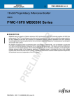
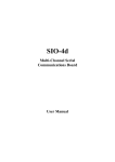
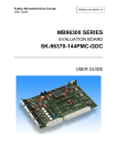
1
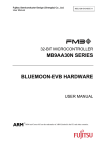
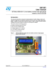
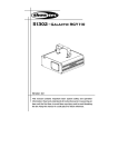
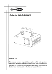
MB91470 Family Motor Control Kit
User Manual
P/N: A91470-MOTOR-Kit
1
Revision History
Revision #
Date
Comment
1.0
1.25.09
New Document
2
Warranty and Disclaimer
To the maximum extent permitted by applicable law, Fujitsu Microelectronics America Inc restricts its warranties and
its liability for the Product [ ], its performance and any consequential damages, on the use of the Product in accordance
with (i) the terms of the License Agreement and the Sale and Purchase Agreement under which agreements the Product
has been delivered, (ii) the technical descriptions and (iii) all accompanying written materials. This product has been
created to work in laboratory environment only. In addition, to the maximum extent permitted by applicable law,
Fujitsu Microelectronics America Inc disclaims all warranties and liabilities for the performance of the Product and any
consequential damages in cases of unauthorized decompiling and/or reverse engineering and/or disassembling.
1.
Fujitsu Microelectronics America Inc. warrants that the Product will perform substantially in
accordance with the accompanying written materials [this manual] for a period of 90 days form the
date of receipt by the customer. Concerning the hardware components of the Product, Fujitsu
Microelectronics America warrants that the Product will be free from defects in material and
workmanship under use and service as specified in the accompanying written materials for a
duration of 1 year from the date of receipt by the customer.
2.
Should a Product turn out to be defect, Fujitsu Microelectronics America Inc. entire liability and the
customer’s exclusive remedy shall be, at Fujitsu Microelectronics America Inc sole discretion, either
return of the purchase price and the license fee, or replacement of the Product or parts thereof, if
the Product is returned to Fujitsu Microelectronics America Inc in original packing and without
further defects resulting from the customer’s use or the transport. However, this warranty is
excluded if the defect has resulted from an accident not attributable to Fujitsu Microelectronics
America Inc, or abuse or misapplication attributable to the customer or any other third party not
relating to Fujitsu Microelectronics America Inc.
3.
To the maximum extent permitted by applicable law Fujitsu Microelectronics America Inc disclaims
all other warranties, whether expressed or implied, in particular, but not limited to, warranties of
merchantability and fitness for a particular purpose for which the Product is not designated.
4.
To the maximum extent permitted by applicable law, Fujitsu Microelectronics America Inc and its suppliers´
liability is restricted to intention and gross negligence.
NO LIABILITY FOR CONSEQUENTIAL DAMAGES
To the maximum extent permitted by applicable law, in no event shall Fujitsu
Microelectronics America Inc and its suppliers be liable for any damages whatsoever
(including but without limitation, consequential and/or indirect damages for personal injury,
assets of substantial value, loss of profits, interruption of business operation, loss of
information, or any other monetary or pecuniary loss) arising from the use of the Product.
Should one of the above stipulations be or become invalid and/or unenforceable, the remaining stipulations shall stay in
full effect.
Date: 22.01.99, V1.0
3
Contents
1. Overview.....……………………………………………………………..… Page 05
1.1 Overview…………………………………………………………….Page 05
1.2 Evaluation Kit Features………………………………………… Page 05
1.3 Supported Microcontroller Series………………………………..Page 05
2. Fujitsu Motor Control Starter Kit Components.......................................Page 06
2.1 Inverter board…………........................................................... Page 06
2.2 MCU board…………................................................................Page 07
2.3 Interface between MCU and Inverter Board………………….. Page 09
2.4 Interface between MCU, Inverter Board and Motor............... Page 10
3. Board Configuration......................................................................... .. Page 11
3.1 MCU board………………………………………………………. Page 11
3.1.1 Jumper and Switches………………………………… Page 11
3.2 Inverter Board
3.2.1 BLDC motor control –Hall sensor ……………………..Page 18
3.2.2 BLDC motor control –sensorless………………………Page 18
4. Motor Specification……………………………………………………….. Page 19
4.1 BLDC Motor……………………………………………………….. Page 19
4.2 PMSM motor …………………………………………………… . Page 19
5. Motor Control Kit Operation…………………………………………… . Page 20
5.1 Mode Configuration………………………………………
…... Page 20
5.2 Starter kit Default mode………………………………………...... Page 20
5.3 Motor Operation…………………………………………………….Page 20
5.4 LEDs Indication……………………………………………………..Page 20
6. Monitoring Motor control Parameter………..………………………….. Page 22
7. Error Condition on Starter Kit …..……………………………………… Page 23
8. Programming MCU board……………………………………………… Page 24
9. Jumper and Connector Summary……………………………………… Page 25
9.1 MCU board………………………………………………………… Page 25
9.2 Inverter Board……………………………………………………. . Page 27
9.3 Motor connector…………………………………………………… Page 28
9.4 PMSM motor connector………………………………………… Page 28
10
Recommended Reading……………………………………………… Page 29
11
Appendix
11.1
Definitions, Acronyms and Abbreviations
4
1. Introduction
1.1 Overview
The BLDC/PMSM Motor control kit is an evaluation kit to provide the user a platform to
evaluate the Fujitsu motor control microcontroller and develop the own solution with no external
component. The starter kit is built around the Fujitsu 32 bit MB91F479 microcontroller, which
has the integrated peripheral for motor control application. The motor peripherals can control
three phase motor such as Brushless DC motors, PMSM motor, and Induction motor. The motor
control kit shows how effectively the Fujitsu family of microcontrollers can be used in advanced
motor control application. The motor control kit supports both Hall sensor and a sensorless
control for BLDC motor and sensorless FOC control for PMSM motor.
This document contains detail information for system specification, board physical components,
board connection, installation, demo operation, signal measurement, precaution and trouble
shooting guide for the motor control kit.
1.2 Evaluation Kit Features
•
•
•
•
•
•
•
Self contained, No additional components required for evaluation.
Start/Stop and forward/reverse direction switches.
Hall sensor inputs for sensor brushless dc motor control
Socket for Emulator
Fault indication LEDs
Headers for MCU pins
Support for BLDC and PMSM motor
1.3 Supported Microcontroller series
The kit is designed to work only with MB91475 series. The following MCU parts can be
used with the Kit:
- MB91V470
- MB91F479
5
2.
Fujitsu Motor Control Starter Kit Components
The kit consists of the following major units:
1. Inverter Board
2. MCU Board
3. BLDC/PMSM Motor
MCU Board
Power Board
MCU
BOARD
INVERTER
BOARD
BLDC
MOTOR
6
2.1
Inverter Board
Following picture shows the Inverter board connector details
1
2
3
4
8
5
6
7
9
1.Hall sensor interface connector (Motor)
2.Motor interface connector
3.Power supply input jack
4.Fuse
5.MCU signal interface connector (FRC)
6.Hall sensor interface connector (MCU)
7.EXOR signal interface connector
8.Fault indication LED
9.Power indication LED
7
2.2 MCU Board
Following picture shows the MCU board connector details
14
13
15
12
11
10
9
8
7
1
2
3
1.USB type B connector
2.EXOR signal interface connector
3.Hall / Zero crossing signal interface connector
4.Inverter board signal interface connector
5.Power jack
6.Serial programming connector
7.Special function switch
8.Start/Stop Switch SW1.
9.Reverse (Anti clockwise) direction rotation switch SW3
10.Speed Increase switch SW4
11.Speed Decrease switch SW5
12.Forward (clock wise) direction rotation switch SW6
13.Reset switch
14.Potentiometers P2,P3
15. Potentiometer P1, for closed loop speed control.
8
4
5
6
2.3
Interface Between MCU and Inverter board
Following picture shows the interface between MCU and Inverter board
1
2
1. EXOR signal interfacing connections . J15 of inverter board and J7 of MCU
board.
2. Hall sensor / Zero crossing and Power supply interfacing connection. J7 of
Inverter board and x8 of MCU board.
3. PWM and other signal interfacing connector. J5 of inverter board and X12 of
MCU board.
9
3
2.4
Interface Between MCU, Inverter board and Motor
Following picture shows Motor connection to Inverter board
1
2
1.3 phase power supply for the motor
2.Hall sensor interface.
3.BLDC/PMSM Motor
10
3
3. Board Configuration
This chapter describes all jumpers and switches that can be modified on the evaluation
board. The default setting (for MB91F479) is shown with a grey shaded area.
3.1
MCU Board
3.1.1 Jumper and Switches
3.1.1.1 Power Supply (JP: 26, 41)
The onboard voltage regulator provides stabilized 5V supply to the MCU and peripherals.
Even though it is thermally protected against overload, care must be taken when
supplying current for additional circuitry, like sensors.
JP41 Selects on-board (X15) or ext. (X12) DC input
JP26 Connects the MCU supply to VCC5; can be used for MCU current measurement
Jumper
JP26 (MCU/VCC)
JP41((DCIN EXT/INT)
JP49
Setting
Closed
Description
OPEN
MCUVCC connected to
VCC5
for current measurement
1-2
DC input by X15
2-3
DC input by INVERTER
board (J16)
DC input by inverter Power
board or by X15
USB POWER
1-2
2-3
3.1.1.2 Programming Jumper (JP32)
This jumper is used for the purpose of executing the existing code in MCU or
programming the MCU.
Jumper
JP41((DCIN EXT/INT)
Setting
1-2
Description
RUN Mode
2-3
Programming mode
Note: Switch SW8 is to be set in RUN mode to execute the program in the MCU.
3.1.1.3 Analog Power Supply Voltage (JP: 24, 27, 28, 35, 36)
The power supply as well as the positive reference voltages for the A/D-converters can be
11
provided internally or externally.
JP24, JP35 connects analog power supply voltages (AVcc and AVss)
JP27 connects the analog reference voltage AVRH2 to AVcc
JP28 connects the analog reference voltage AVRH3 to AVcc
JP36 connects the analog reference voltage AVRH4 to AVcc
Jumper Setting
Jumper
Setting
Description
JP24 (AVcc)
Closed
AVcc is connected to Vcc
AVcc is disconnected from Vcc
OPEN
JP27 (AVRH2
Closed
AVRH2 is connected to AVcc
AVRH2 defined by resistor
OPEN
network*1
JP28 (AVRH3)
Closed
AVRH3 is connected to AVcc
AVRH3 defined by resistor
OPEN
network*1
JP36 (AVRH4)
Closed
AVRH4 is connected to AVcc
AVRH4 defined by resistor
OPEN
network*1
JP35 (AVss)
Closed
AVss is connected to GND
AVss is disconnected from
OPEN
GND
*1By default the resistor networks are not mounted on the board
By default, the A/D-converter supply and reference voltages are the same as the
microcontroller supply voltage.
Note:
If JP24 and JP35 are open, the user has to supply an adequate analog voltage supply
(AVcc and AVss) to the A/D-converter.
If JP27 is open, the resistors R27 and R37 define AVRH2.
If JP28 is open, the resistors R26 and R36 define AVRH3.
If JP36 is open, the resistors R43 and R47 define AVRH4.
By default the resistor networks are not mounted on the board. Standard SMD0805 chip
resistors can be used.
3.1.1.4 UART0 (JP: 2, 3, 4)
One RS232-transceiver (U2, X5) can be connected to the microcontrollers UART
interface 0.
JP2, JP3 connect UART 0 to the RS232 transceiver (U2, X5)
JP4 Some programs (e.g. Terminals) need a connection between CTS and RTS
12
Jumper
JP2 (SIN0)
Setting
Closed
OPEN
JP3 (SOT0)
Closed
OPEN
JP4 (RTS-CTS)
Closed
OPEN
Description
SIN0 of MCU is connected
to UART0
SIN0 not connected to
UART0
SOT0 of MCU is connected
to UART0
SOT0 not connected to
UART0
RTS and CTS of X5 are
connected
RTS and CTS of X5 are not
connected
By default, UART0 (SIN0/SOT0) is connected to X5.
UART0 is also used for asynchronous in-circuit Flash programming and also to view the
motor control result.
3.1.1.5 UART1 (JP: 12, 14, 15)
One RS232-transceiver (U3, X6) can be connected to the microcontrollers UART
interface 1.
JP12, JP14 connect UART 1 to the RS232 transceiver (U3, X6)
JP15 Some programs (e.g. Terminals) need a connection between CTS and RTS
Jumper
JP12 (SIN1)
Setting
Closed
OPEN
JP14 (SOT1)
Closed
OPEN
JP15 (RTS-CTS)
Closed
OPEN
By default, UART1 (SIN1/SOT1) is connected to X6.
13
Description
SIN1 of MCU is connected
to UART1
SIN1 not connected to
UART1
SOT1 of MCU is connected
to UART1
SOT1 not connected to
UART1
RTS and CTS of X6 are
connected
RTS and CTS of X6 are not
connected
3.1.1.6 UART2 (JP: 17, 18, 19)
One RS232-transceiver (U4, X7) can be connected to the microcontrollers UART
interface 2.
JP17, JP18 connect UART 2 to the RS232 transceiver (U4, X7)
JP19 Some programs (e.g. Terminals) need a connection between CTS and RTS
Jumper
JP17 (SIN1)
Setting
Closed
OPEN
JP18 (SOT1)
Closed
OPEN
JP19 (RTS-CTS)
Closed
OPEN
Description
SIN2 of MCU is connected
to UART2
SIN2 not connected to
UART2
SOT2 of MCU is connected
to UART2
SOT2 not connected to
UART2
RTS and CTS of X7 are
connected
RTS and CTS of X7 are not
connected
By default, UART2 (SIN2/SOT2) is connected to X7.
3.1.1.7 Reset-Generation (JP: 9, 23, 25, 30)
In addition to the internal Power-On reset, the microcontroller can be reset by an external
reset circuit (Voltage Monitor) and also by a RS232 interface.
JP9 This jumper selects whether the DTR line from UART0 or UART1 will generate a
system reset.
JP23 This jumper connects the MCU Pin 17 (Base timer output TOUT3) to the external
watchdog IC’s trigger input
JP25 Open this jumper if no external Reset shall be generated, e.g. to avoid accidental
reset during long-term testing or demonstration.
JP30 This jumper enables the watchdog function of the reset IC U5. If this is closed, U5
U5 issues a reset if it is not periodically re-triggered by the MCU (PJ7/TOUT3)
Jumper
JP9
Setting
1-2
2-3
14
Description
DTR of UART0 is selected
for reset generation
DTR of UART1 is selected
for reset generation
JP23 (WD_TOUT3)
Closed
MCU Pin 17 (PJ7/TOUT3)
connected to U5
MCU Pin 17 (PJ7/TOUT3)
not connected to U5
INITX connected to reset
circuit / supply monitor U5
No connections to INITX
OPEN
JP25 (Ext. Reset)
Closed
OPEN
JP30 Closed U5 watchdog
function enabled
(Watchdog)
Closed
U5 watchdog
enabled
U5 watchdog
disabled
OPEN
function
function
Note:
While a reset signal is asserted the red Reset-LED (LED16) is lit. During normal
operation, this LED should be off.
If the reset LED is steadily on or blinks periodically, check the power supply input
voltage and the settings for the reset generation by UART as well as the jumpers JP23
and JP30.
3.1.1.8 Buttons SW1-SW7 (JP: 1, 5, 6, 8, 10, 11, 25, 38)
JP1, JP5, JP8, JP10, JP11, JP38
Six user push buttons SW1-SW6 can be connected to the microcontroller.
SW2 also serves as test button for the MCU DTTI function, which stops the PWM output
e.g. in case of an inverter fault.
JP6 Common interrupt for SW3-SW6: Eases up button event handling when the
buttons are used to control an application
JP25 External reset circuit and button SW7 can be connected to the microcontroller.
Jumper
JP1 (SW1)
Setting
Closed
OPEN
JP38 (SW2)
Closed
OPEN
15
Description
NMIX of the MCU is
connected to SW1
No connection to the
microcontroller
DTTI button + LED15
connected to MCU Pin 57
(DTTI)
No connection to the
microcontroller
JP5 (SW3)
JP8 (SW4)
Closed
Pin 23 (INT3) of MCU is
connected to SW3 and JP6
OPEN
No connection to the
microcontroller
Pin 14 (TIN2) is connected
to SW4
No connection to the
microcontroller
Pin 56 (CKI0) of the MCU
is connected to SW5
No connection to the
microcontroller
Pin 67 (ADTG4) of the
MCU is connected to SW6
No connection to the
microcontroller
SW3 - SW6 connected to
INT3 (wired-OR)
(COMM. INT)
Only SW3 is connected to
INT3
Closed
OPEN
JP10 (SW5)
Closed
OPEN
JP11 (SW6)
Closed
OPEN
JP6
Closed
OPEN
JP25 (Reset)
Closed
INITX is connected to the
reset IC and SW7
No connection to INITX
OPEN
By default, all push-buttons as well as the reset circuit are connected to the
microcontroller.
For Motor control operation the switches are used for the following functionality:
•
•
•
•
•
•
Start/Stop Switch. (SW1)
It is used to start or stop the motor. Default condition will be stop.
Reverse (Anti clockwise) direction rotation switch.( SW3)
It is used to rotate the motor in reverse direction.
Speed Increase switch. (SW4)
This is used to increase the speed of motor while in open loop control.
Speed Decrease switch.( SW5)
It is used to decrease the speed of motor while in open loop control.
Forward (clock wise) direction rotation switch. (SW6)
It is used to rotate the motor in forward direction.
Reset switch (SW7)
This switch will reset the controller.
16
•
•
Potentiometer (P1)
It is used for closed loop speed control. Anti clockwise rotation will result in
decrease of speed while clockwise rotation will result in increase of speed.
Switch ( SW14)
Decide for sensored/sensorless BLDC Motor Control. If on SW14, A=0, B=0,
then the code will execute for sensorless control. If A=1, B=0, then the code will
execute for Hall sensored control.
SW1
Start/Stop
SW4
Speed Increase
SW5
Speed Decrease
17
SW6
SW3
POT P1
Forward rotation Reverse rotation Closed
Loop
3.2
1.
2.
3.
4.
Inverter Board sections
Power supply jack, 12V. This is the power to be supplied to run the motor.
Connector for BLDC/PMSM Motor Phases.
Connector for BLDC Motor Hall sensors and power.
IGBT module. It supplies the 3 phase PWM to Motor.
Inverter Board Connectors
jumper setting
J1
12V power supply
J2
Motor Phase
J15
To J7 on MCU board
J7
To X8 on MCU board
J5
To X12 on MCU board
Fuse F1
connect 1.5A fuse
Jumper J3, J4, J11
Closed
3.2.1 BLDC Motor Control - Hall Sensor
•
•
•
Connector J6 should be populated with Hall connector.
Jumpers J8, J9, J10 should be in position 2-3 (near to hall connector).
In switch SW14 on MCU board, A=1, B=0
J6 on Inverter board
Should be populated with Hall Connector
Jumper J8, J9, J10 on Inverter board
Should be in position 2-3
Switch SW14 on MCU
A=1(ON); B=0 (OFF)
3.2.2 BLDC Motor Control - Sensorless
•
•
Jumpers J8, J9, J10 should be in position 1-2 (away from hall connector).
In switch SW14 on MCU board, A=0, B=0.
3.2.3 PMSM Motor Control - Sensorless
Motor Connected to the inverter board should be PMSM motor. No extra conditions
required
18
4. Motor Specification
4.1
BLDC Motor
The kit comes with the following motor
Manufacture: BLDC motor from BPMC
P/N:
BL2644 -12-004 is a
Specification: 3 phase, 12V
4.2
PMSM Motor
The motor control kit can also be used with PMSM motor. The PMSM motor tested with
the hardware:
Manufacture: Faulhaber
P/N:
1628T 012B
Specification:
3 phase, 12V BLDC
19
5
Motor control Kit Operation
5.1 Motor Control Mode configuration
Motor can operate in two Modes: Open, Closed.
•
•
•
•
•
Default mode is Closed loop mode.
Motor operates in closed loop by varying the Potentiometer P1 on MCU board.
Motor can switch to open loop mode by pressing UP/DWN button on MCU board.
Once the control is switched from closed loop mode to open loop mode, the control stays
in open loop mode. It cannot be switched back to closed mode.
Open and closed loop modes are followed both in sensored and sensorless control.
5.2 Starter Kit Default Mode
•
•
•
Motor control will be in Closed loop mode.
Motor will RUN in forward (clock wise) direction.
Required speed and control will depend on Pot P1 position.
5.3 Motor operation (Open/closed loop)
•
•
•
•
•
When the power is given to the starterkit, it will not start until user presses the Start/Stop
Button. When the Start/Stop button is pressed again the Motor will Stop.
When the start button is pressed the Motor will attain the required speed and it will run in
closed loop mode. Error will be corrected through the software and in a short period
required and actual speed will be same. The required speed can be varied by P1
Potentiometer (on MCU board).
The Actual and Required Speed can be observed on the Hyper Terminal (UART 0 of
MCU board with 2400,8,N,1 baud setting).
Whenever Up or Down Button is pressed the motor will come out of the Closed loop and
it will run in Open Loop Mode. The Motor will always remain in Open Loop if the Up or
Down Button is Pressed.
In Running condition the direction of the motor can be changed by Pressing the FWD or
REV Button.
5.4.1 LED's Indication
5.4.1.1 LEDs on Power ON
•
•
•
•
•
LED D2 : ON.
LED17 : ON.
LED26 : ON
LED1 :ON
LED10, LED12, LED14 :ON
20
5.4.1.2 LEDs when Start button (SW2) Pressed
•
LED9, LED11, LED13 : ON
5.4.1.3 LEDs when Reset button (SW7) Pressed
•
LED16 : ON (RED)
21
6. Monitor Motor Control Parameters by UART0
The UART0 can be used for monitoring the Actual and Required Speed of the motor
using Hyper Terminal software on PC. The required settings are as follows:
Baud rate: 2400,8, N,1
In case of closed loop control, both Actual and Required speed will change.
•
•
•
Required speed can be changed through Pot P1 on MCU board.
Actual speed will be controlled through sensored/sensorless algorithm through
software.
In case of open loop control, only Actual speed can be changed through switches
SW4 & SW5.
22
7. Error Condition on Starter kit
•
•
•
•
•
LED D1 on Inverter power board will be RED.
If this LED is RED for more than 5 seconds, press the RESET switch on the
MCU board.
When the Start button is pressed (or during run state), and if the motor is not
running smoothly or stalling or still, then press the RESET switch on the MCU
board.
If the above mentioned conditions are repeated despite pressing reset switch,
switch OFF the power supply, check if all the connections are made and are
intact. Verify the Jumper position.
If the problem is not solved after all the above mentioned steps then contact
support team.
23
8.0 Programming MCU board
•
•
•
•
•
•
Remove the power to Inverter power board. Connectors J1/J16 should be unpopulated.
Connect the power to MCU board. Connect X15 with 12V power supply.
Switch SW8 is to be set in PROG mode in MCU board.
Jumper JP41 to be in ADPT DC IN position on MCU board.
Connect UART0 of MCU board with a RS232 connector/cable and the other end should
be on the PC side.
Run the Fujitsu Flash Programmer software and program the hex file.
24
9 Jumpers and Connector Summary
9.1 MCU board
Component
Description/Operation (MCU Board)
JP41
This Jumper selects power for MCU board either form DC Adapter or form the
external DC power source (I.e. From inverter board )
Pin 1 & 2 Short : Power from DC Adapter
Pin 2 & 3 Short : Power form external DC source
JP25
Enables External reset when connected
JP2 JP3 JP4
Connects RS232 transceiver to UART0 when shorted
JP12 JP14 JP15
Connects RS232 transceiver to UART1 when shorted
JP17 JP18 JP19
Connects RS232 transceiver to UART2 when shorted
JP49
This Jumper selects power for MCU board either form Voltage regulator on
MCU board or form USB
Pin 1 & 2 Short : Adepter or external DC power (Through voltage regulator)
Pin 2 & 3 Short : USB power
JP1 JP5 JP8 JP10
JP11 JP38
Enables the switches when shorted
JP6
Enables common interrupt when shorted
JP44
Enables GND to be connected to X12 Connector when shorted
JP45
Enables LED18 when shorted
JP42 JP37
For connecting signals form X12 to MCU
JP40
Enables PWM LEDs when shorted.
JP7 JP13 JP16
Enables Potentiometer to be connected to MCU when shorted
SW14
For motor selection
JP20 JP21 JP22
Connects Hall/Zero crossing signal to MCU
X12
This connector carries signals between MCU to Inverter board
This connector includes signals for interfacing Inverter board as follows
Pin 1 GND
Pin 2 GND
Pin 3 PWM H1
Pin 4 PWM L1
Pin 5 PWM H2
Pin 6 PWM L2
Pin 7 PWM H3
Pin 8 PWM L3
Pin 9 GND
Pin 10 GND
Pin 11 VCC_MCU
Pin 12 VCC_MCU
Pin 13 FAULT/Enable
25
Pin 14 NC
Pin 15 NC
Pin 16 NC
Pin 17 NC
Pin 18 TEMP signal
Pin 19 FAULT
Pin 20 NC
Pin 21 GND
Pin 22 NC
Pin 23 GND
Pin 24 NC
Pin 25 GND
Pin 26 NC
Pin 27 GND
Pin 28 ITrip
Pin 29 GND
Pin 30 PCU
Pin 31 GND
Pin 32 PCV
Pin 33 GND
Pin 34 PCW
X8
Hall/Zero crossing signal interfacing connector
Pin 1 : VCC
Pin 2 : GND
Pin 3 : Hall 1
Pin 4 : Hall 2
Pin 5 : Hall 3
J7
EXOR signal interfacing connector
Pin 1 : GND
Pin 2 : EOR
LED26
ON when Adapter power is pluged
LED17
Power ON indication
LED16
ON when RESET switch is pressed
26
9.2 Inverter board
Component
Description/Operation (Inverter Board)
J8 J9 J10
selects Either zero crossing signals when Pin 1 & 2 short or Hall signals when
Pin 2 & 3 short
J11 J12 J13 J14
Selects the signal for MCU Interrupt generation when shorted
J4
For Enabling power supply for MCU board
Shorted : Enables supply
Open: Disables supply
J3
For Enabling power supply for IGBT module
Shorted : Enables supply
Open: Disables supply
J6
Hall sensor interface connector (Motor)
Pin 1 : VCC
Pin 2 : GND
Pin 3 : Hall 1
Pin 4 : Hall 2
Pin 5 : Hall 3
J7
Hall sensor interface connector (MCU board)
Pin 1 : VCC
Pin 2 : GND
Pin 3 : Hall 1
Pin 4 : Hall 2
Pin 5 : Hall 3
J15
For connecting EXOR signal to MCU board
J5
This connector carries signals between MCU to Inverter board
J1
12V Power supply input through standard power adapter
F1
Fuse 1A
J2
Motor connector
Pin 1: Phase U
Pin 2 :Phase V
Pin 3 :Phase W
D1
Error Indication LED.
D2
Power ON Indication
27
9.3 Motor Connector
9.3.1 BLDC Motor
Function
Wire Color
A Phase
Brown
B Phase
Orange
C Phase
White
A Hall Sensor
Blue
B Hall Sensor
Green
C Hall Sensor
Yellow
+6V Logical Supply
Red
GND Logical
Black
9.3.2 PMSM Motor
Function
Wire Color
A Phase
Brown
B Phase
Orange
C Phase
Yellow
A Hall Sensor
Green
B Hall Sensor
Blue
C Hall Sensor
Grey
+5V Logical Supply
Red
GND Logical
Black
28
10.
Recommended Reading
This document describes how to use the Fujitsu Motor Control Kit. Additional technical
information can be found on the following documents.
•
•
•
•
MB91F479 Data sheet
Fujitsu motor Control Kit Schematic
Fujitsu motor control software for BLDC/PMSM motor
Fujitsu motor control Application Note for Sensored BLDC and sensorless
BLDC/PMSM
29
11. Appendix
11.1 Definitions, Acronyms and Abbreviations
BLDC
:
Brushless DC Motor
BEMF
:
Back Electro Magnetic Force
PWM
:
Pulse Width Modulation
PI
:
Proportional-Integral
IGBT
:
Insulated Gate Bipolar Transistor
PMSM
:
Permanent Magnet Synchronous Motor
FOC
:
Field oriented control for PMSM
30