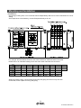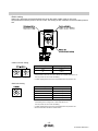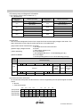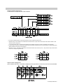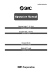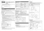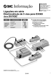
1
No.EX※※-OMF0006-C PRODUCT NAME SI unit for CC-Link MODEL / Series / Product Number EX250-SMJ2 Table of Contents Safety Instructions 2 Model Indication and How to Order 7 Summary of Product elements 7 Mounting and Installation 8 Installation 8 Wiring 9 Setting 14 Maintenance 19 Troubleshooting 20 Specifications 22 Specifications 22 Dimensions 23 Option 24 Refer to the operation manual EX250-IE1/-IE2/-IE3 for the input block specifications, and EX9-OET1/-OET2/-OEP1/-OEP2/-PE1 for the output block and power block specifications. -1No.EX※※-OMF0006-C Safety Instructions These safety instructions are intended to prevent hazardous situations and/or equipment damage. These instructions indicate the level of potential hazard with the labels of "Caution", "Warning" or "Danger". They are all important notes for safety and must be followed in addition to International standards (ISO/IEC) 1) and other safety regulations. 1) ISO 4414: Pneumatic fluid power -- General rules relating to systems. ISO 4413: Hydraulic fluid power -- General rules relating to systems. IEC 60204-1: Safety of machinery -- Electrical equipment of machines. (Part 1: General requirements) ISO 10218-1992: Manipulating industrial robots -Safety. etc. Caution : Warning : Danger : CAUTION indicates a hazard with a low level of risk which, if not avoided, could result in minor or moderate injury. WARNING indicates a hazard with a medium level of risk which, if not avoided, could result in death or serious injury. DANGER indicates a hazard with a high level of risk which, if not avoided, will result in death or serious injury. Warning 1. The compatibility of the product is the responsibility of the person who designs the equipment or decides its specifications. Since the product specified here is used under various operating conditions, its compatibility with specific equipment must be decided by the person who designs the equipment or decides its specifications based on necessary analysis and test results. The expected performance and safety assurance of the equipment will be the responsibility of the person who has determined its compatibility with the product. This person should also continuously review all specifications of the product referring to its latest catalog information, with a view to giving due consideration to any possibility of equipment failure when configuring the equipment. 2. Only personnel with appropriate training should operate machinery and equipment. The product specified here may become unsafe if handled incorrectly. The assembly, operation and maintenance of machines or equipment including our products must be performed by an operator who is appropriately trained and experienced. 3. Do not service or attempt to remove product and machinery/equipment until safety is confirmed. 1. The inspection and maintenance of machinery/equipment should only be performed after measures to prevent falling or runaway of the driven objects have been confirmed. 2. When the product is to be removed, confirm that the safety measures as mentioned above are implemented and the power from any appropriate source is cut, and read and understand the specific product precautions of all relevant products carefully. 3. Before machinery/equipment is restarted, take measures to prevent unexpected operation and malfunction. 4. Contact SMC beforehand and take special consideration of safety measures if the product is to be used in any of the following conditions. 1. Conditions and environments outside of the given specifications, or use outdoors or in a place exposed to direct sunlight. 2. Installation on equipment in conjunction with atomic energy, railways, air navigation, space, shipping, vehicles, military, medical treatment, combustion and recreation, or equipment in contact with food and beverages, emergency stop circuits, clutch and brake circuits in press applications, safety equipment or other applications unsuitable for the standard specifications described in the product catalog. 3. An application which could have negative effects on people, property, or animals requiring special safety analysis. 4. Use in an interlock circuit, which requires the provision of double interlock for possible failure by using a mechanical protective function, and periodical checks to confirm proper operation. -2No.EX※※-OMF0006-C Caution The product is provided for use in manufacturing industries. The product herein described is basically provided for peaceful use in manufacturing industries. If considering using the product in other industries, consult SMC beforehand and exchange specifications or a contract if necessary. If anything is unclear, contact your nearest sales branch. Limited warranty and Disclaimer/Compliance Requirements The product used is subject to the following "Limited warranty and Disclaimer" and "Compliance Requirements". Read and accept them before using the product. Limited warranty and Disclaimer 1. The warranty period of the product is 1 year in service or 1.5 years after the product is delivered, whichever is first. 2) Also, the product may have specified durability, running distance or replacement parts. Please consult your nearest sales branch. 2. For any failure or damage reported within the warranty period which is clearly our responsibility, a replacement product or necessary parts will be provided. This limited warranty applies only to our product independently, and not to any other damage incurred due to the failure of the product. 3. Prior to using SMC products, please read and understand the warranty terms and disclaimers noted in the specified catalogue for the particular products. 2) Vacuum pads are excluded from this 1 year warranty. A vacuum pad is a consumable part, so it is warranted for a year after it is delivered. Also, even within the warranty period, the wear of a product due to the use of the vacuum pad or failure due to the deterioration of rubber material are not covered by the limited warranty. Compliance Requirements 1. The use of SMC products with production equipment for the manufacture of weapons of mass destruction (WMD) or any other weapon is strictly prohibited. 2. The exports of SMC products or technology from one country to another are governed by the relevant security laws and regulation of the countries involved in the transaction. Prior to the shipment of a SMC product to another country, assure that all local rules governing that export are known and followed. -3No.EX※※-OMF0006-C Operator This operation manual is intended for those who have knowledge of machinery using pneumatic equipment, and have sufficient knowledge of assembly, operation and maintenance of such equipment. Only those persons are allowed to perform assembly, operation and maintenance. Read and understand this operation manual carefully before assembling, operating or providing maintenance to the product. ■Safety Instructions Warning ■Do not disassemble, modify (including changing the printed circuit board) or repair. An injury or failure can result. ■Do not operate the product outside of the specifications. Do not use for flammable or harmful fluids. Fire, malfunction, or damage to the product can result. Verify the specifications before use. ■Do not operate in an atmosphere containing flammable or explosive gases. Fire or an explosion can result. This product is not designed to be explosion proof. ■If using the product in an interlocking circuit: •Provide a double interlocking system, for example a mechanical system. •Check the product regularly for proper operation. Otherwise malfunction can result, causing an accident. ■The following instructions must be followed during maintenance: •Turn off the power supply. •Stop the air supply, exhaust the residual pressure and verify that the air is released before performing maintenance. Otherwise an injury can result. Caution ■After maintenance is complete, perform appropriate functional inspections. Stop operation if the equipment does not function properly. Safety cannot be assured in the case of unexpected malfunction. ■Provide grounding to assure the safety and noise resistance of the SI unit. Individual grounding should be provided close to the product with a short cable. -4No.EX※※-OMF0006-C ■NOTE ○Follow the instructions given below when designing, selecting and handling the product. The instructions on design and selection (installation, wiring, environment, adjustment, operation, maintenance, etc.) described below must also be followed. Product specifications •When conformity to UL is required, the SI unit should be used with a UL1310 Class 2 power supply. mark on the body. •The SI unit is a UL approved product only if they have a •Use the specified voltage. Otherwise failure or malfunction can result. •Reserve a space for maintenance. Allow sufficient space for maintenance when designing the system. •Do not remove any nameplates or labels. This can lead to incorrect maintenance, or misreading of the operation manual, which could cause damage or malfunction to the product. It may also result in non-conformity to safety standards. Product handling Installation •Do not drop, hit or apply excessive shock to the SI unit. Otherwise damage to the product can result, causing malfunction. •Tighten to the specified tightening torque. If the tightening torque is exceeded the mounting screws may be broken. IP67 protection cannot be guaranteed if the screws are not tightened to the specified torque. •Never mount a product in a location that will be used as a foothold. The product may be damaged if excessive force is applied by stepping or climbing onto it. Wiring •Avoid repeatedly bending or stretching the cables, or placing heavy load on them. Repetitive bending stress or tensile stress can cause breakage of the cable. •Wire correctly. Incorrect wiring can break the product. •Do not perform wiring while the power is on. Otherwise damage to the SI unit and/or I/O device can result, causing malfunction. •Do not route wires and cables together with power or high voltage cables. Otherwise the SI unit and/or I/O device can malfunction due to interference of noise and surge voltage from power and high voltage cables to the signal line. Route the wires (piping) of the SI unit and/or I/O device separately from power or high voltage cables. •Confirm proper insulation of wiring. Poor insulation (interference from another circuit, poor insulation between terminals, etc.) can lead to excess voltage or current being applied to the product, causing damage. •Take appropriate measures against noise, such as using a noise filter, when the SI unit is incorporated into equipment. Otherwise noise can cause malfunction. -5No.EX※※-OMF0006-C Environment •Select the proper type of protection according to the environment of operation. IP67 protection is achieved when the following conditions are met. (1)The units are connected properly with fieldbus cable with M12 connector and power cable with M12/M8 connector. (2)Suitable mounting of each unit and manifold valve. If using in an environment that is exposed to water splashes, please take measures such as using a cover. •Do not use in a place where the product could be splashed by oil or chemicals. If the product is to be used in an environment containing oils or chemicals such as coolant or cleaning solvent, even for a short time, it may be adversely affected (damage, malfunction etc.). •Do not use the product in an environment where corrosive gases or fluids could be splashed. Otherwise damage to the product and malfunction can result. •Do not use in an area where surges are generated. If there is equipment which generates a large amount of surge (solenoid type lifter, high frequency induction furnace, motor, etc.) close to the SI unit, this may cause deterioration or breakage of the internal circuit of the SI unit. Avoid sources of surge generation and crossed lines. •When a surge-generating load such as a relay or solenoid is driven directly, use an SI unit with a built-in surge absorbing element. Direct drive of a load generating surge voltage can damage the SI unit. •The product is CE marked, but not immune to lightning strikes. Take measures against lightning strikes in the system. •Prevent foreign matter such as remnant of wires from entering the SI unit to avoid failure and malfunction. Otherwise failure or malfunction can result. •Mount the product in a place that is not exposed to vibration or impact. Otherwise failure or malfunction can result. •Do not use the product in an environment that is exposed to temperature cycle. Heat cycles other than ordinary changes in temperature can adversely affect the inside of the product. •Do not expose the product to direct sunlight. If using in a location directly exposed to sunlight, shade the product from the sunlight. Otherwise failure or malfunction can result. •Keep within the specified ambient temperature range. Otherwise malfunction can result. •Do not operate close to a heat source, or in a location exposed to radiant heat. Otherwise malfunction can result. Adjustment and Operation •Set the switches by using a sharp-pointed screwdriver etc. It may damage set switches. •Perform settings suitable for the operating conditions. Incorrect setting can cause operation failure. For details of each setting, refer to page 14 of this manual. •Please refer to the PLC manufacturer's manual etc. for details of programming and addresses. For the PLC protocol and programming refer to the relevant manufacturer's documentation. Maintenance •Turn off the power supply, stop the supplied air, exhaust the residual pressure and verify the release of air before performing maintenance. There is a risk of unexpected malfunction. •Perform regular maintenance and inspections. There is a risk of unexpected malfunction. •After maintenance is complete, perform appropriate functional inspections. Stop operation if the equipment does not function properly. Otherwise safety is not assured due to an unexpected malfunction or incorrect operation. •Do not use solvents such as benzene, thinner etc. to clean the SI unit. They could damage the surface of the body and erase the markings on the body. Use a soft cloth to remove stains. For heavy stains, use a cloth soaked with diluted neutral detergent and fully squeezed, then wipe up the stains again with a dry cloth. -6No.EX※※-OMF0006-C Model Indication and How to Order EX250-SMJ2 Communication protocol MJ2 CC-Link Summary of Product elements No. Element Description 1 Communication connector Connect with CC-Link communication line. (Accessory) 1 2 Power supply connector Supplies power to the solenoid valve, the output block, SI unit and the input block. 1 3 Input block connector Connects the input block. 4 Output block connector Connects the solenoid valve, output block and etc. 5 Display LED display shows the SI unit status. 2 6 Switch protective cover Set Station no. and Baud rate by using the switches under the cover. 2 7 Ground terminal (FE) Used for grounding. 1: Refer to page 9 for Wiring. 2: Refer to page 14 for the Setting. -7No.EX※※-OMF0006-C Mounting and Installation ■Installation Not having mounting hole, it can not be set to BUS independently. Be sure to connect manifold to SI unit for setting. And if input block is unnecessary, connect End plate directly to SI unit. For example, the table below shows the size when manifold of VQC1000 series connected. Please refer to an individual catalog for the size when other manifolds are connected. L N_m L1 L2 L N_m 0 1 2 3 4 5 6 7 8 45 55.5 66 76.5 87 97.5 108 118.5 129 89.8 110.8 131.8 152.8 173.8 194.8 215.8 236.8 257.8 9 10 11 12 13 14 15 16 L1 139.5 150 L2 278.8 299.8 160.5 171 181.5 192 202.5 213 (mm) Wiring (for power supply, communication and input) and piping are done on only one side. On the side, make a space for wiring and piping. -8No.EX※※-OMF0006-C ■Wiring ○Communication wiring SI unit Bus adapter Shield with twist pair cable DA From master station, remote station, local station DB DG IN SLD DA To remote station, local station DB OUT DG SLD Terminating resistor Shield (SLD) is connected to the ground terminal (FE) inside of the SI unit. ○Terminating resistor If the SI unit is the terminal of CC-Link connection, connect the terminal resistor to "OUT" side of the bus adapter. There are two types of terminal resistors depending on the cable to use. Refer to the following table and select an appropriate terminal resistor. Cable to use Manufacturer Correns PHOENIX CONTACT Ver.1.10-compatible CC-Link dedicated cable CC-Link dedicated cable (110 Ω, 1/2 W) CC-Link dedicated high-performance cable (130 Ω, 1/2 W) Model Color of molded portion Model Color of molded portion VA-4DCC-110 Black VA-4DCC-130 Gray SAC-4P-M12MS CCL TR Black -9No.EX※※-OMF0006-C ○Power supply wiring Power supply line inside the SI unit has individual power supplies for solenoid valve actuation (SV power supply) and for control parts and input block (SW power supply). Supply 24 VDC for each of them. : In case of single power supply, pay attention to the range of each supply voltage. Power for sensor is supplied to sensor connected with input block. Select sensor concerning voltage drop up to maximum 1 V inside the unit at this moment. If sensor requires 24 V, it is necessary to lower power supply voltage for sensor slightly or secure power supply for sensor separately without going through SI unit so that sensor input voltage can be 24 V with actual loading (allowable voltage of power supply: 19.2 to 28.8 V). -10No.EX※※-OMF0006-C ○Ground terminal Connect the ground terminal to ground. Resistance to ground should be 100 ohms or less. -11No.EX※※-OMF0006-C ○Communication connector (Bus adapter: EX9-ACY00-MJ) LINK IN: M12 4-pin plug No. Description Function 1 SLD Shield 2 DB Communication wire DB 3 DG Communication wire DG 4 DA Communication wire DA Example of the cable with connector: PCA-1567720 (manufactured by SMC) Example of the connector: PCA-1557620 (manufactured by SMC) LINK OUT: M12 5-pin socket No. Description Function 1 SLD Shield 2 DB Communication wire DB 3 DG Communication wire DG 4 DA 5 - Communication wire DA Not used Example of the cable with connector: PCA-1567717 (manufactured by SMC) Example of the connector: PCA-1557617 (manufactured by SMC) BUS adapter: The EX9-ACY00-MJ is a special accessory for this product. It is not suitable for use with other products. ○Power supply connector M12 5-pin plug, reverse key No. Description Function 1 SV24 V +24 V power supply for solenoid valve 2 SV0 V 0 V power supply for solenoid valve 3 SW24 V +24 V for power supply for control and input block 4 SW0 V 0 V for power supply for control and input block 5 FE Earth Example of the cable with connector: EX9-AC010-1 (1 m) EX9-AC030-1 (3 m) EX9-AC050-1 (5 m) etc. (manufactured by SMC) -12No.EX※※-OMF0006-C ○Maintenance Addition of input block •Remove the screws from the end plate to remove the plate. •Mount the additional tie rods (supplied with the input block). •Connect additional input block. •Re-mount the end plate that was removed, and tighten the screws to the specified tightening torque. (0.6 Nm) Replacing the SI unit •Remove the screws from the end plate and release the connection with the valve unit. •Replace the SI unit. (There is no need to remove the tie rod.) •Re-mount the input block and end plate that was removed, and tighten the screws to the specified tightening torque. (0.6 Nm) Precautions for maintenance (1)Turn off the power supply completely. (2)Check that there is no foreign matter inside the unit. (3)Check that there is no damage and no foreign matter on the gasket. (4)Tighten the screws to the specified torque. If the unit is not assembled correctly, this may cause product failure due to foreign matter such as liquid and dust which may get into the unit. ○Assembly and disconnection of unit -13No.EX※※-OMF0006-C Setting ○LED indication LED indication PW PW (V) Description Light is ON: Input and control power is ON. Light is OFF: Input and control power is OFF. Light is ON: When power supply for solenoid valves is turned ON. Light is OFF: When supply voltage decreases below 19 V. L RUN Light is ON: Communication is normal. Light is OFF: Communication terminated. (Time over error) L ERR Light is ON: Communication error. Flashing: Assignment of station no. and baud rate are made during communication. (Flicker every 0.4 s) Light is OFF: Communication is normal. "PW", "PW(V) ", "L RUN" light while data link is normal. -14No.EX※※-OMF0006-C ○Switch setting Station No., Baud rate and HOLD/CLEAR are set by the switch inside of the SI unit cover. Set parameters while the power of SI unit is OFF. The setting of each switches can be fixed after power is ON. •Station number setting Setting Setting range x10 0 to 6 x1 0 to 9 : The station number should be set within the range of 01 to 64. If the number is set to 00, or to 65 or above, the “L ERR” LED will turn on. Turn the power off, and correct the setting. : "L ERR" display blinks if the switch is operated which the power is ON. •Baud rate setting Setting Baud rate 0 156 kbps 1 625 kbps 2 2.5 Mbps 3 5 Mbps 4 10 Mbps : The baud rat should be set within the range of 0 to 4. If the setting is out of range, the “L ERR” LED will turn on. Turn the power off, and correct the setting. : "L ERR" display blinks if the switch is operated which the power is ON. : Set the same baud rate as the master station. -15No.EX※※-OMF0006-C •HOLD/CLEAR setting Setting Description Function H (ON) HOLD Hold the output when an communication error occurs. L (OFF) CLEAR Clear the output when an communication error occurs. •Adjusted when shipped Please refer to the table below for setting at the time of shipment from the factory. Set parameters B RATE (Baud rate) STATION NO. HOLD/CLEAR Switch setting Contents 0 156 kbps x10 0 x1 0 0 OFF CLEAR -16No.EX※※-OMF0006-C ○I/O memory map and diagnostic information (1)I/O memory map (in case of station No. 1) Ex.) “QJ61BT11N” Buffer memory address Buffer memory address Remote input (RX) RX F to RX 0 E0H RX1F to RX10 RX2F to RX20 Profile area RY1F to RY10 OUT31 to OUT16 RY2F to RY20 162H RX3F to RX30 E3H OUT15 to OUT 0 161H IN31 to IN16 E2H RY F to RY 0 160H IN15 to IN0 E1H Remote output (RY) Not available RY3F to RY30 163H Profile area Not available : For detail of profile area, refer to “Profile area”. (2)Profile area The SI unit has a diagnostic function for the input block fuse and the supply voltage to the valves. The status information is sent using the profile area shown in the table below. (a)Input block broken fuse detection 0: Normal 1: One input block fuse is disconnected 0: Normal (b)Valve supply voltage lowered 1: Valve supply voltage is low 0: SI unit operating (c)Error status flag 1: SI unit stopped (Not turn on “1” when detecting (a) to (b).) 0: SI unit stopped (d)Remote READY 1: SI unit operating (Not turn off “0” when detecting (a) to (b).) Buffer memory address Remote input (RX) RX2F … RX2C RX2B E2H E3H RX2A RX29 … RX23 Reserve RX3B RX21 RX20 Over current Valve supply Reserve detection of voltage lowered input Reserve RX3F … RX3C RX22 RX3A RX39 … RX33 RX32 Remote READY Error state flag RX31 RX30 Reserve Reserve (L): Reserved bit (0 fixing), Reserve (H): Reserved bit (1 fixing) (3)Fuse disconnection information SI unit solenoid valve power fuse disconnection can be recognized by the link special register at master station. 0: Normal 1: Fuse disconnected b15 b14 b13 b12 … b3 b2 b1 b0 (688H)SW0088 16 15 14 13 … 4 3 2 1 (689H)SW0089 32 31 30 29 … 20 19 18 17 36 35 34 33 52 51 50 49 (68AH)SW008A 48 47 46 45 … (68BH)SW008B 64 63 62 61 … 1 to 64 shows station number. Bits of occupied station turn on. -17No.EX※※-OMF0006-C ○Output number assignment Combinations of output data and valve manifold : The output numbering refers to the solenoid position on the manifold and starts at zero. : Standard wiring of the manifold is for double-solenoid valves and the output number starts at the A side and then B side in that order as shown in the figure a. If a single-solenoid valve is mounted on the standard wiring manifold, the output number for the B side valve is skipped. : Custom wiring for mixed mounting single-solenoid valves and double-solenoid valves can be specified with a Wiring Specification Sheet. Example wiring is shown in the figure b. : Bit status “0” and ”1” in the data corresponds to solenoid valve status OFF and ON (0: OFF, 1: ON), and the output number starts at zero from LSB (least significant bit). ○Input number assignment Input numbers start from 0, and will be assigned to the input blocks in order from the SI unit mounted side. -18No.EX※※-OMF0006-C Maintenance •Mounting and wiring Item to inspect Criteria Countermeasure Confirm the connectors (communication, power supply) of SI unit securely connected. No looseness. Tighten the resistance. Confirm the terminating resistance securely connected to the both ends of the CC-Link system. (in case this system is at the end of the network) No looseness. Tighten the resistance. Confirm the connecting cable broken. No appearance error If any error is found on the appearance, replace the cable. •Replacement parts Item to inspect Criteria Countermeasure CC-Link applicable cable for moving part (when used) No error on the appearance and conductive resistance value If any error is found on the appearance or the conductive resistance, replace the cable. See the specification of a cable to be used for the conductive resistance. SI unit No error in operation and display If any error is found in the operation or on the display, replace the unit. Criteria Countermeasure •Power supply Item to inspect Confirm the voltage satisfy the specified range. Measure the voltages at the both sides of SI unit controlling part's power supply. 24 VDC ±20% Investigate into the cause of voltage fluctuation, and take a countermeasure against it. Confirm the voltage satisfy the specified range. Measure the voltages at the both sides of the power supply for solenoid valves. 24 VDC +10%/-5% (Refer to “Electrical and communication specifications” on page 22.) Investigate into the cause of voltage fluctuation, and take a countermeasure against it. -19No.EX※※-OMF0006-C Troubleshooting When SI unit does not operate properly, follow the flow chart below and resolve it. Solenoid valve does not operate. PW(V) LED is displayed? NO Power supply for solenoid valve is applied? YES NO Apply power supply for control and Input block. Contact to SMC. YES NO PW LED is displayed? Apply power supply for solenoid valve. YES YES LED for solenoid valve is displayed? NO NO Power supply for control and input block is applied? YES L RUN LED is displayed? YES NO Written to correct address of remote output RY (Buffer memory)? YES Contact to SMC. NO Write to the correct address. SD, RD LED of master station is displayed? NO Check if wiring is disconnected or shot circuit, and check program assignment. Refer to Mitsubishi’s users manual for details. YES Baud rate assignment is correct? NO Set Baud rate assignment correctly. YES Not duplicated with other station? NO Set correct station number. YES Contact to SMC. -20No.EX※※-OMF0006-C Input block is not recognized. Contact to SMC. YES PW LED is displayed? NO Power supply for SI unit and input block is applied? NO Apply power supply for SI unit and input block. YES PWR for input block is displayed? NO See Input block operation manual. If Input signal is still unrecognized, contact to SMC. NO Turn on Input block sensor. If Input signal is still unrecognized, contact to SMC. YES Sensor ON LED for input block is displayed? YES L RUN LED is displayed? YES NO Read from correct address of remote input RX (Buffer memory)? YES Contact to SMC. NO Write to the correct address. SD, RD LED for master is displayed. NO Check if wiring is disconnected or short circuit, and check program assignment. Refer to Mitsubishi’s user’s manual for details. YES Baud rate assignment is correct? NO Set Baud rate assignment correctly. YES Not duplicated with other station? NO Set correct station number. YES Contact to SMC. -21No.EX※※-OMF0006-C Specifications ■Specifications General specifications Item Specification o Operating ambient temp. 5 to 45 C Operating ambient humidity 35 to 85% RH (No dew condensation) Storage ambient temp. -20 to 60 C Withstand voltage 500 VAC, 1 minute Insulation resistance 500 VDC, 10 M ohm Operating environment No corrosive gas Pollution degree Pollution degree 3 Enclosure IP67 Standard CE marking, UL (CSA) Weight 250 g or less Electrical and communication specifications Item Power voltage range, current consumption Solenoid valve connection specification Communication specification Specification Power supply for control and input block and current consumption 24 VDC ±20% Depending on the number of input block stations and sensor specifications: 1.1 A or less (Inside SI unit: 0.1 A or less) Power supply for solenoid valve and current consumption 24 VDC ±10%/-5% Depending on number of solenoid valve station and specifications: 2.0 A or less Output type NPN (positive common) / sink Connection load Solenoid valve with surge voltage suppressor of 24 VDC and 1.5 W or less (manufactured by SMC) Residual Voltage 0.3 VDC or less Insulation type Photo coupler insulation type Station number assignment range 1 to 63 (Assigned by the rotary switch) Baud rate setting range 156 k/625 k/2.5 M/5 M/10 Mbps (Assigned by the rotary switch) Applicable system CC-Link Ver.1.10 Occupied station 2 stations Station type Remote device station I/O points Input/32 points, Output/32 points : The condition for allowable voltage fluctuation to solenoid valve that is 24 VDC ±10. Please confirm the allowable voltage fluctuation range of solenoid valve that is installed in SI unit and set the power supply voltage in consideration of Max. 5% voltage drop across SI unit. Applicable solenoid valves Representative series Applicable series SY series SY3000, SY5000, SY7000 VQC series VQC1000, VQC2000, VQC4000 SV series SV1000, SV2000, SV3000 (Tie rod base manifold) S0700 series S0700 -22No.EX※※-OMF0006-C ■Dimensions •EX250-SMJ2 -23No.EX※※-OMF0006-C Option 1. CC-Link communication connector cable Cable O.D. 7.7 Nominal cross section area 0.5 mm2 AWG20 Wire diameter 2.55 mm Minimum bending radius 77 mm (Fixed) 2. CC-Link communication assembly type connector Applicable cable Wire outer diameter 4.0 to 8.0 mm Wire gauge (stranded wire cross section) 0.14 to 0.5 mm2 AWG26 to 20 Cable O.D. 6.4 Nominal cross section area 0.3 mm2 Wire diameter 0.16 mm Minimum bending radius 40 mm (Fixed) 3. Power supply connector cable 4. Spare fuse (for input block) -24No.EX※※-OMF0006-C 5. Electrical entry connector cable Cable O.D. φ6.4 Nominal cross section area 0.3 mm2 Wire diameter 0.16 mm Minimum bending radius 40 mm (Fixed) 6. Power supply connector cable (for power supply to the power block) Cable O.D. 6.4 Minimum bending radius 40 mm (Fixed) 7. Input block relay connector cable M12 connector Cable O.D. 4.7 Minimum bending radius 47 mm (Fixed) M8 connector Cable O.D. 4.4 Minimum bending radius 44 mm (Fixed) 8. Input block assembly type connector -25No.EX※※-OMF0006-C 9. End plate (on the input block side) EX250-EA1 EX250-EA2 EX9-EA03 EX9-EA04 10. End plate R (on the output block side) 11. Waterproof cap Mount this to the unused ports of the input block, output block and power block. Proper use of the waterproof cap enables the enclosure to achieve IP67 specification. (The power block is provided with the product.) Note Tighten the waterproof caps to the tightening torque specified. (M8: 0.05 Nm, M12: 0.1 Nm) -26No.EX※※-OMF0006-C Revision history A: Correct an error in writing B: Complete revision C: Complete revision Note: Specifications are subject to change without prior notice and any obligation on the part of the manufacturer. © 2008-2014 SMC Corporation All Rights Reserved No.EX※※-OMF0006-C