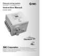
1
Reduced wiring system
EtherNet/IP™ Compatible GW Unit
Instruction Manual
EX500-GEN1
URL http:// www.smcworld.com
Specifications are subject to change without prior notice and any obligation on the part of the manufacturer.
EtherNet/IP™ is a trademark used under licence by ODVA.
The descriptions of products shown in this document may be used by the other companies as their trademarks.
© 2006 SMC Corporation All Rights Reserved
Contents
Thank you for purchasing the SMC reduced wiring system EX500 series.
SAFETY ..........................................................................................................2
Please read this instruction manual carefully and understand the contents before
Product Summary............................................................................................5
use so that you can operate this unit safely and correctly.
EX500
Please keep this manual handy for future reference.
Part Names ...................................................................................................6
Dimensions ...................................................................................................7
Installation .....................................................................................................7
Specification..................................................................................................8
Wiring ..........................................................................................................11
Display/Switch setting .................................................................................18
SI Unit
Part Names .................................................................................................21
Dimensions .................................................................................................22
Mounting/Wiring ..........................................................................................23
Specification................................................................................................24
Display ........................................................................................................25
Input Unit Manifold
Part Names .................................................................................................26
Dimensions .................................................................................................27
Installation ...................................................................................................28
Specification................................................................................................29
Wiring ..........................................................................................................30
OPERATOR
Display ........................................................................................................31
This instruction manual has been written for those who have knowledge of
machines and equipments that use reduced wiring system as well as the
sufficient knowledge to assemble, operate, and maintain such devices.
Before performing assembly, operation and/or maintenance, please read
this manual carefully and understand the contents.
EX9 Series General Purpose Output Block
Part Names .................................................................................................32
Dimensions .................................................................................................33
Mounting .....................................................................................................34
Wiring ..........................................................................................................35
Specification................................................................................................38
Display .......................................................................................................39
Option ............................................................................................................40
Troubleshooting.............................................................................................42
To facilitate recycling, this
manual is printed using
biodegradable soy ink, which
can easily be de-inked.
This manual is printed in the
"non-water system", which does
not output toxic liquid waste.
SAFETY
The body of unit and this manual contain the essential information for the protection of
users and others from possible injury and property damage and to ensure correct
handling.
Please check that you fully understand the definitions of the following messages
( symbols ) before going on to read the body of this manual, and always follow the
instructions.
Please also read the instruction manuals etc. of related machines and equipments and
understand the contents before use.
Before performing maintenance:
Turn off power supply.
Stop air supply, exhaust compressed air in piping, and confirm the release
to atmosphere.
Otherwise injury can result.
IMPORTANT MESSAGES
Read this manual and follow its instructions. Signal words such as WARNING,
CAUTION and NOTE will be followed by important safety information that must be
carefully reviewed.
NOTE
Conduct proper functional inspection after completing maintenance.
In the case of abnormality such as unit does not work normally, stop the operation.
Otherwise safety cannot be assured due to unintended malfunction.
Indicates a potentially hazardous situation that could result in
death or severe injury if you do not follow instructions.
Provide grounding to improve safety and noise resistance of reduced wiring
system.
Indicates a potentially hazardous situation that, if not avoided,
may result in minor injury or moderate injury.
Provide grounding as close to the unit as possible to shorten distance for grounding.
Gives you helpful information.
Handling precautions
Use the following UL-recognized DC power supply to combine with.
Do not disassemble,
modify ( including modification of printed circuit board ) or repair.
Otherwise injury or failure can result.
Do not operate beyond specification range.
Otherwise fire, malfunction or damage to the reduced wiring system can result.
Confirm the specifications before operation.
Do not operate in atmosphere of flammable/explosive/corrosive gas.
Otherwise fire, explosion or corrosion can result.
This reduced wiring system is not explosion-proof type.
For use in interlock circuit:
Provide double interlock system by adding different type of protection
( such as mechanical protection ).
Check that the interlock circuit is working normally.
1. UL508-compatible limited voltage/current circuit
A circuit using the secondary coil of an insulating transformer that meets following conditions
as power source.
Maximum voltage ( at no load ) : 30Vrms ( 42.4Vpeak ) or below
Maximum current :
( 1 ) 8A or less ( including when short-circuited )
( 2 ) When limited by the circuit protector ( such as fuse )
having the following rating.
No-Load Voltage ( Vpeak )
Max. Current Rating ( A )
0 to 20 [V]
5.0
Above 20 [V] to 30 [V]
100/peak voltage
2. UL1310-compatible Class 2 power supply unit or circuit of max. 30Vrms ( 42.4Vpeak ) or less
using a UL1585-compatible Class 2 transformer as power source. ( Class 2 circuit )
Otherwise accident caused by malfunction can result.
2
3
SAFETY ( continued )
Follow the instructions given below when handling your reduced wiring system.
Otherwise a damage or failure to cause a malfunction can result.
Operate the reduced wiring system at the specified voltage.
Reserve space for maintenance.
Do not remove any name plate or label.
Do not drop, hit or apply an excessive shock to the unit.
Follow the specified tightening torque.
Do not apply any excessive force to cables by repeated bending, tensioning or placing a
heavy object on the cables.
Connect wires and cables correctly.
Do not perform any wiring work while the power is on.
Do not use the reduced wiring system on the same wiring route as the power line or high
voltage line.
Confirm the insulation of wiring.
Perform the power supply wiring by dividing into two lines ---- one is for power supply for output
and the other is for power supply for input and controlling GW/SI.
Take sufficient measures against noise such as noise filter when incorporating the reduced
wiring system into a machine or equipment.
Mount a terminal plug or a waterproof cap on each unused M12 connector for input/output
( communication connector, communication ports A - D, and power supply for input and
controlling GW/SI ).
Take sufficient shielding measures when operating the product in any of the following places.
( 1 ) A place where noise due to static electricity etc. is generated
( 2 ) A place of high electric field strength
( 3 ) A place where exposure to radioactivity is possible
( 4 ) A place near power cable
Do not operate the product in a place where there is a source of surge.
Use a surge absorbing element built-in type to directly drive the load that generates surge
voltage such as solenoid valve.
Prevent any foreign matter such as remnant of wires from getting inside the product when
opening the station number switch protective cover.
Install the reduced wiring system in a place free from vibration and impact.
Operate the product in the specified ambient temperature range.
Do not use in a place to be affected by the radiant heat from a surrounding heat source.
Set the DIP switch and rotary switch by using a sharp-pointed watchmakers screwdriver etc.
Perform the maintenance regularly.
Conduct an appropriate functional inspection after completing the maintenance.
Do not use chemicals such as benzin and thinner to clean the product.
4
Product Summary
System configuration general
EtherNet/IP
communication connector
GW unit
Power supply
connector cable
( 24VDC for solenoid
valves/output, 24VDC for
input and controlling GW/SI )
Manifold valve
with SI unit
( SV/VQC series )
Manifold valve
with SI unit
( SV/VQC series )
Input unit manifold
Branch cable
with M12 connector
Branch cable
with M12 connector
Input unit manifold
The reduced wiring system is connected to various kinds of fieldbus realizes the
reduced wiring and decentralized installation of I/O devices. The signals to/from
fieldbus are exchanged by GW unit, and the signals to/from decentralized I/O devices
are collected and delivered by GW unit.
The maximum number of connections of manifold valve/Input unit manifold is
16/branch x 4 branches = 64 points each for output and input.
As the cables with connectors are used for all wirings among devices, the system
complies with the IP65 environment.
5
EX500 Part Names
Dimensions ( unit : mm )
EX500 body
148
PE
GATEWAY UNIT
EX500 SERIES
PWR
LINK
100
12
63
73
88
MS
NS
24VDC
COM A
COM B
COM C
EX500-GEN1
LAN
COM D
No.
1
Name
Communication
connector
Application
Connect with EtherNet/IP line. ( Note 1 )
2
Power supply connector
Supply power for output devices such as solenoid
valve, for input devices such as sensor, and for
controlling GW/SI by using power supply connector
cable. ( Note1 )
3
Communication port A
( COM A )
5
Communication port B
( COM B )
Communication port C
( COM C )
Installation ( unit : mm )
Thread mounting
Connect SI unit ( manifold valve ) or Input unit by
using branch cable with M12 connectors. ( Note1 )
Secure at four positions with screws with head diameter of 5.2 or more and thread
length of 15mm or more.
148
4 M5
Tightening torque :
(1.5 0.2) N m
6
Communication port D
( COM D )
7
Display
Display the power supply status and communication
status with PLC. ( Note2 )
8
Station number switch
protective cover
Set IP address and communication method by using
the switches under this cover. ( Note2 )
Cutout Dimensions for Mounting ( Tolerance :
68 5
4
10
46
48.8
160
136
0.2 )
Note1 : For wiring method, refer to subsection "Wiring" ( page 11 ) of section "EX500" in this
manual.
Note2 : For display and setting method, refer to subsection "Display/Switch Setting" ( page 18 )
of section "EX500" in this manual.
6
7
Specification
Basic specifications
I/O mapping
Input area mapping
Rated voltage
24VDC
Range of power
supply voltage
Power supply for input and controlling GW/SI : 24VDC 10%
Power supply for output : 24VDC+10%/-5% ( Voltage drop
warning at around 20V )
Rated current
Power supply for input and controlling GW/SI : 3.0A
Inside GW unit : 0.2A
Input device and SI control section : 2.8A
Power supply for solenoid valves and output : 3A
)
(
Number of input/
output points
Input point : Max. 64/Output point : Max. 64
Higher-level bus
Protocol
Ethernet ( IEEE802.3 )
100BASE-TX
Communication
speed
10M/100Mbps ( Automatic selection or manual setting )
Max. segment length
100m ( 328ft )
Max. transceiver number
2 ( per segment )
Communication
method
Full duplex/Half duplex ( automatic selection or manual
setting )
I/O message
Port No.
IP address setting range
Device information
LSB MSB
15
LSB
8 7
0
0
15
COM-A
0
1
2
15
COM-B
0
Sensor
15
COM-C
0
input area
3
15
4
L
L
L
L
L
L
L
L
L
L
L
L
L
L
L
L
5
L
L
L
L
L
L
L
L
L
L
L
L
L
L
L
L
6
L
L
L
L
L
L
L
L
L
L
L
L
L
L
L
L
7
L
L
L
L
L
L
L
L
L
L
L SOLV IN-A IN-B IN-C IN-D
COM-D
0
Status
input area
L : Fixed to Low ( reserved area )
Media
Fieldbus protocol
Input data
Offset
(word) MSB
EtherNet/IP™ Release1.0
Input : 16 byte ( assembly instance : 100 )
Output : 16 byte ( assembly instance : 150 )
Status input area specifications
Item
Condition
The power supply of
solenoids
SOLV
1) The input unit detected
0
The connection of
branched bus
IN-
2) The SI unit with a wire open detection detected
1
Wire open detected
0
Supply voltage OK
1) Supply voltage below lower limit
1
2) No supply voltage
Output area mapping
Input data
Offset
(word) MSB
LSB MSB
15
0
44818 ( 0xAF12 )
1
192.168.0.1 to 192.168.0.254 ( Setting by an internal switch )
Or optional setting by the DHCP server
Vendor ID
: 7 ( SMC Corp. )
Product type : 12 ( communication adapter )
Product code : 104
Status
LSB
8 7
0
15
COM-A
0
15
COM-B
0
Output
2
15
COM-C
0
area
3
15
4
L
L
L
L
L
L
L
L
L
L
L
L
L
L
L
L
5
L
L
L
L
L
L
L
L
L
L
L
L
L
L
L
L
6
L
L
L
L
L
L
L
L
L
L
L
L
L
L
L
L
7
L
L
L
L
L
L
L
L
L
L
L
L
L
L
L
L
COM-D
0
L : Fixed to Low ( reserved area )
8
9
Wiring
Lower-level bus
Internal circuit
Number of branches for
input/output
Communication method
Branch current for input
( Note )
Branch current for output
Branch cable length
4 branches ( 16 points/branch ) for input
4 branches ( 16 points/branch ) for output
Protocol : Dedicated for SMC
Speed : 750kbps
Communication
connector
+Tx
+Rx
- Tx
- Rx
1
2
3
4
Max. 0.5 [A] per branch ( when SI unit and input
devices are connected )
Max. 0.65 [A] per branch
( when SI unit EX500-S 01 is connected )
Max. 0.75 [A] per branch
( when SI unit EX500-Q
is connected )
5m or less between devices
( total extended length : 10m or less )
DC-DC
converter
Power supply
for output
0V
Power
+24V
Power supply
supply
0V
connector for input and
+24V
controlling GW/SI PE
1
2
3
4
5
Note : Total value of maximum current consumption and maximum load current of input devices
to connect.
Internal circuit
Specification ( continued )
1
2
3
4
5
6
7
8
RD+
RD TD+
TD +24V
0V
+24V
0V
COM A
1
2
3
4
5
6
7
8
RD+
RD TD+
TD +24V
0V
+24V
0V
COM D
The wirings is explained in the following order.
Communication wiring : Connection with EtherNet/IP
Power supply wiring : Connections of power supplies for
solenoid valves/output devices, and for
input devices and controlling GW/SI
Branch wiring : Connection from GW unit to SI unit or Input unit
10
11
Wiring ( continued )
Power supply wiring
Communication wiring
Connect the cable with Ethernet communication connector to the communication
connector of GW unit.
1
2
Connect the power supply connector cable to the power supply connector of GW unit.
There are two types of cables different in connector shape ---- straight type and angle
type. With this cable, the power is supplied to the output devices such as solenoid valve,
and the input devices such as sensor, and for controlling GW/SI. Therefore, there is no
need to supply the power to other units individually.
When selecting the power supply, refer to "Handling precautions" ( page 3 ) in this manual.
4
3
Cable connection
Cable connection
Aligning the key groove with the communication connector
( 4-pin, socket ) of GW unit, plug the Ethernet
communication cable ( plug ).
Tighten the lock nut on cable side by turning it
clockwise by hand.
Aligning the key groove with the power supply
connector ( plug ) of GW unit, plug the power supply
cable ( socket ).
Confirm that the connector portion does not move.
Tighten the lock nut on cable side by turning it
clockwise by hand.
Confirm that the connector portion does not move.
Pin layout and connection diagram of power supply connector cable for ( unit : mm )
Pin layout and connection diagram of cable with Ethernet communication connector
Connect the communication cable with socket-type M12 connector to the
communication connector of GW unit.
M12
6
6
M12
14.9
28.3
RJ45
6.7
M12
( Pin layout and connection diagram are common to all cables. )
18
30
34
48
5
50
31.3
30
5
50
47.3
2000
45
Straight connector Type
EX500-AP -S
EX9-AC020EN-PSRJ
2
3
1
4
Cable core wire external color
Terminal No.
+Tx
+Rx
- Tx
- Rx
1
2
1 White/Orange 34
2 Orange
5
3 White/Green 6
7
4
8
1
2
3
4
5
6 Green
7
8
Pin assignment of
plug connector
Wiring diagram
Pin assignment of
plug connector
Pin No.
1
Cable color: Signal name
Brown : 0V ( for solenoid valves/output )
2
White : 24VDC +10%/-5% ( for solenoid valves/output )
3
Blue : 0V ( for input and controlling GW/SI )
4
Black : 24VDC
5
Gray : Ground ( PE )
10% ( power supply for input and controlling GW/SI )
1
2
5
4
3
Socket Connector Pin Layout
Shield
Cable specifications
12
Angle connector Type
EX500-AP -A
Core wire color
AWG 26
Sheath color
Blue green
NOTE
Connect a ground cable of 100
or less to PE terminal.
13
Wiring ( continued )
Separate wiring for power supply for solenoid valves/output and
for input and control of GW/SI
Both single power supply and two power supply systems can be adopted, however, the
wiring shall be made separately ( for solenoid valves/output and for input and controlling
GW/SI ) for either system.
Branch wiring
For wiring with solenoid valves or input devices, connect the branch cable with M12
connector to communication ports A to D.
There are two types of cables different in connector shape ---- straight type and angle
type. As each cable contains power supply wire, there is no need to supply the power to
solenoid valves or input devices individually.
A. Two power supplies
Cable connection
Brown : 0V ( for solenoid valves/output )
White : 24VDC ( for solenoid valves/output )
2
5
Gray : Ground ( PE )
24VDC
Blue :
1
0V ( for input and controlling GW/SI )
3
Black : 24VDC ( for input and controlling GW/SI )
8
1
8
2
2
1
4
3
7
7
3
Power supply
connector
24VDC
Cable Part No. : EX500-AP
6
-
B. Single power supplies
White : 24VDC ( for solenoid valves/output )
2
1
5
Gray : Ground ( PE )
Blue :
4
4
6
5
5
Socket Connector Pin Layout
Plug Connector Pin Layout
Tighten the lock nut on cable side by
turning it clockwise by hand.
Brown : 0V ( for solenoid valves/output )
24VDC
Aligning the key groove with the
connector ( socket ) of GW unit, plug in
the cable ( plug ).
Confirm that the connector portion does
not move.
0V ( for input and controlling GW/SI )
3
Black : 24VDC ( for input and controlling GW/SI )
4
Power supply
connector
Cable Part No. : EX500-AP
-
NOTE
Mount a waterproof cap on each unused connector of GW unit. The proper use of
waterproof cap can achieve IP65 Enclosure. ( Tightening torque : 0.1N m for M12 )
14
15
Wiring (continued )
For GW unit – Manifold valve – Input unit manifold configuration
For GW unit – Input unit manifold configuration
Two communication connectors in SI unit and one communication connector in Input
unit are installed respectively.
To the communication connector ( C2 ) or ( 1 ) of SI unit, connect the branch cable with
M12 connector from GW. To the communication connector ( C1 ) or ( 0 ), connect the
branch cable with M12 connector from Input unit.
To the communication connector of Input unit, connect the branch cable with M12
connector from SI unit.
To the communication connector of Input unit, connect the branch cable with M12
connector from GW unit.
GW unit
GW unit
Manifold valve with SI unit
( for SV/VQC series )
Branch cable
with M12 connector
Connector ( C1 ) / ( 0 )
Connector ( C2 ) / ( 1 )
Input unit manifold
Type, pin layout and connection diagram of the branch cable with M12 connector ( EX500-AC
Branch cable
with M12 connector
)
L
48
Input unit manifold
52
16
6
M12
Manifold valve with SI unit
( for SV/VQC series )
14.9
NOTE
When no Input unit is connected
to the connector ( C1 ) or ( 0 ) of
SI unit, mount a terminal plug on
the connector.
-
M12
Straight Connector Type
EX500-AC
-SSPS
M12
M12
28.3
32.3
6
Terminal plug
31.3
31.3
L
Angle Connector Type
EX500-AC
-SAPA
L = 300, 500, 1000, 3000, 5000 ( mm )
16
17
Display/Switch Setting
Display
Switch setting
Open the station number switch protective cover and set the switches with a
sharp-pointed watchmakers screwdriver etc.
GATEWAY UNIT
LAN
EX500 SERIES
PWR
LINK
100
MS
NS
COM A
COM B
COM C
COM D
NOTE
1. Be sure to turn off the power before setting the switches.
2. Be sure to set these switches before use.
3. After opening and closing the station number switch protective cover, tighten the
screws by proper tightening torque. ( Tightening torque : 0.6N m )
SW1
SW2
ON
1
Display
PWR
LINK
100
MS
NS
COM A
COM B
COM C
COM D
Off
Green lights up
Off
Green lights up
Green flashes
Off
Green lights up
Off
Green lights up
Green flashes
Red flashes
Red lights up
Off
Green flashes
Green lights up
Red flashes
Red lights up
Off
Green lights up
Off
Green lights up
Off
Green lights up
Off
Green lights up
Content
The power supply for solenoids lowering
The power supply for solenoids normal
The power supply off/initialized
Ethernet communication established
Data sent/received
Communication at 10Mbps
Communication at 100Mbps
The power supply off
Operating normally
Setting error
Recoverable internal error
Unrecoverable internal error
The power supply off/IP address not set
EtherNet/IP-level communication not established
Multiple EtherNet/IP-level communications established
Multiple EtherNet/IP-level communications time out
IP address duplicated
No input data
Input data received
No input data
Input data received
No input data
Input data received
No input data
Input data received
NOTE
When connecting manifold valve only without connecting Input unit manifold, LEDs of
COM A to D do not light. To make them light, connect a terminal plug to the unused
connector of SI unit ( "C1" or "0" ).
18
0
1
2
3
4
5
6
7
IP address
192.168.0.X
1
0
1
0
1
2
0
0
1
1
3
0
0
0
0
SW1
4 5
0 0
0 0
0 0
0 0
6
0
0
0
0
7
0
0
0
0
8
0
0
0
0
0 1 1 1 1 1 1 1
1 1 1 1 1 1 1 1
SW2
3 4 5
Item
8
1
2
3
4
5
Reserved area
Set it to off
X
Remote control *1
1
2
3
Communication
setting
Manual set up
of IP address *3
254
CLR/HOLD
DHCP mode *2
Content
1 -
AUTO : The communication setting is automatically
selected.
Communication
setting
MANUAL : The communication setting follows
the setting result by the switch No. 4 and 5.
1
1
1
1
- Communication
speed
0 Communication
method
1
0 -
0
1
-
6
-
SW2
6
0
1
Communicated at 10Mbps
Communicated at 100Mbps
Communicated at half duplex
Communicated at full duplex
Content
The output signal is cleared when the communication error occurs.
The output signal is held when the communication error occurs.
19
Display/Switch Setting (continued )
*1 : Remote control (SW1 all dip-switches off)
SMC's EX500 GW Unit will respond to the following Rockwell Automation
BOOTP/DHCP Server commands.
Enable DHCP
Selecting this function will enable the EX500 GW Unit to retrieve its boot information
from the BOOTP/DHCP Server. If DHCP is enabled the EX500 GW Unit will retrieve its
boot information during the next power up.
SI Unit Part Names
The SI unit is the unit to communicate with GW unit in combination with manifold valve.
It can be used with SV series valves and VQC series valves.
In addition, this unit is able to operate solenoid valves, relays. etc. in combination with
EX9 series general purpose output block. For how to use it, refer to section "EX9 Series
General Purpose Output Block" ( page 32 ) in this manual.
1. SI unit for SV series valves ( EX500-S
01 )
Disable BOOTP/DHCP
Selecting this function will disable the EX500 to retrieve its boot information from the
BOOTP/DHCP Server, and causes the EX500 to retain its current configuration during
the next power up.
*2 : DHCP Mode (SW1 all dip-switches on)
The IP address is acquired via DHCP Server. The IP address is not saved and lost if the
power to the EX500 unit is cycled.
*3 : Hardware Addressing
SI unit for
SV series
The IP address range is 192.168.0.1-192.168.0.254.
Default settings
At the time of factory shipment, the product is in "Remote Control Mode" and set to
"Enable DHCP".
2. SI unit for VQC series valves ( EX500-Q
)
NOTE
If the stored IP address of an EX500 is not known, please go to the "DHCP Mode" section.
SI unit for
VQC series
( EX500-Q 01 )
Common to EX500-S
01/EX500-Q
No.
Name
Application
1
Communication
connector "C1" or "0"
Connects the branch cable to Input unit ( branch cable
with M12 connector ). ( Note1 )
2
Communication
connector "C2" or "1"
Connects the branch cable from GW unit ( branch
cable with M12 connector ). ( Note1 )
3
Power LED
Indicates the power supply status. ( Note2 )
4
Communication LED
Indicates the communication status with GW unit. ( Note2 )
Note1 : For wiring method, refer to subsection "Wiring" ( page 15 ) of section "EX500" in this
manual.
Note2 : For display, refer to "Display" ( page 25 ) in section "SI Unit" in this manual.
20
21
Dimensions ( unit : mm )
Mounting/Wiring
1. SI unit for SV series valves ( EX500-S
The mounting and removing methods of SI unit are as shown below.
01 )
79.4
28.6
M3 30 : 4 pcs.
( Plus-minus slot
round head screw )
15.5
39
54.5
68.5
Supply/exhaust block
assembly
SI Unit for SV Series Valves ( EX500-S
01 )
COM
PWR
2. SI unit for VQC series valves
( EX500-Q 01 )
80.3
64.4
28
60
0
22.2
43.2
1
10.5
( EX500-Q
M3 10 : 2 pcs.
( Hexagon socket head cap
screw ( with spring washer ))
Supply/exhaust block
assembly
02 )
EX500
series
COM
PWR
SI UNIT
SI Unit for VQC Series Valves ( EX500-Q
NOTE
Holding with hand so that there will be no gap between SI unit and Air supply/exhaust
block assembly, tighten the bolts. Be sure to tighten each bolt by specified tightening
torque. ( Tightening torque : 0.6N m )
66
80.3
01 )
36
64.4
0
22.2
85.7
22
13.2
43.2
60
1
10.5
44
Note 1 For branch wiring method, refer to subsection "Wiring" ( page 15 ) of section "EX500"
in this manual. As the power to output devices such as solenoid valve is supplied by
branch wiring ( branch cable with M12 connector ), there is no need to supply power
individually.
Note 2 For mounting/installation methods of solenoid valve, manifold, etc., refer to the
catalogs, instruction manuals, technical data, etc. of each valve series.
When connecting general purpose output block only, refer to subsection "Mounting"
( page 34 ) of section "EX9 Series General Purpose Output Block" in this manual.
23
Specification
Display
1. SI unit for SV series valve ( EX500-S
Item
Connected block
Connected block
station
01 )
Specification
Double solenoid valve
Relay output module ( 2-point output )
Max. 8 stations
Single solenoid valve
Relay output module ( 1-point output )
Max. 16 stations
24VDC
Supply current for block
0.65A Max.
Current consumption
100mA or less ( at rated voltage )
2. SI unit for VQC series valve ( EX500-Q
Item
Connected block
station
01 )
Solenoid valve ( single, double )
Relay output module ( 1-point output, 2- point output )
Supply voltage for block
Connected block
SI unit for SV series valves ( EX500-S
Power LED
Communication LED
)
Specification
SI unit for VQC series valves ( EX500-Q
Solenoid valve ( single, double )
General purpose output block ( EX500-Q
02 only )
Double solenoid valve
Max. 8 stations
Single solenoid valve
Max. 16 stations
General purpose output block
( EX500-Q 02 only )
Max. 8 stations
Supply voltage for block
24VDC
Supply current for block
0.75A Max.
Current consumption
100mA or less ( at rated voltage )
)
Communication LED
Power LED
3. Applicable valve series
Series
Manifold
Cassette
Tie-rod
Inner diameter of applicable cylinder tube ( mm )
40
50
63
80
100
SV1000
125
Common to EX500-S
Display
SV2000
SV3000
-
SV4000
-
VQC1000
-
VQC2000
-
VQC4000
-
01/EX500-Q
Description
Power LED
Lights on : Power to solenoid valves/output is supplied at the
specified voltage.
Lights off : Power to solenoid valves/output is not supplied at
the specified voltage. ( Voltage dropped to lower
than 20V. )
Communication
LED
Lights on : Receiving data from GW
Lights off : No received data
For detailed specifications of solenoid valve and manifold, refer to the catalogs, instruction
manuals, technical data, etc. of each valve series.
24
25
49
DIN Rail
Do not mix sensor input specifications ( PNP and NPN ).
(L4)
5
Stations
(7.5)
44.2
L3
L2 ( Rail mounting pitch: 12.5 )
L1
39.7
Note
When only input blocks for M8 connector are connected
32.2
The Input unit manifold consists of Input unit, input block (s), end block and DIN rail.
The input block up to 8 can be connected ( 16 points ).
Any combination of input blocks ( for M8 connector, M12 connector and 8-pointintegrated type ) is acceptable.
Dimensions ( unit : mm )
35
Input Unit Manifold Part Names
1
2
3
4
5
6
7
8
98
110.5
123
135.5
148
160.5
173
185.5
L2 [mm] : Mounting pitch
87.5
100
112.5
125
137.5
150
162.5
175
L3 [mm] : Manifold length
74
86
98
110
122
134
146
158
L4 [mm]
12
12
12.5
12.5
13
13
13.5
13.5
L1 [mm] : Rail length
Figure shows the configuration when only input blocks for M8 connector are connected.
No.
Part name
Application
1
Input unit
Unit to communicate with GW unit or SI unit.
2
Communication
connector
To be connected with branch cables from GW unit or
SI unit ( branch cable with M12 connector ). ( Note1 )
3
Power LED
Indicates the power supply status. ( Note2 )
4
Input block
Unit for sensor signal input.
5
Sensor connector
Connects with sensor. ( Note1 )
6
Indicator LED
Indicates sensor signal status. ( Note2 )
7
Marker
To be used for writing input No. etc.
8
End block
Composes the end of Input unit manifold.
9
DIN rail
To be mounted with Input unit manifold.
When only input blocks of 8-point-integrated type are connected
Stations
1
2
135.5
185.5
L2 [mm] : Mounting pitch
125
175
L3 [mm] : Manifold length
110
158
L4 [mm]
12.5
13.5
L1 [mm] : Rail length
Note1 : For wiring method, refer to subsection "Wiring" ( page 30 ) of section "Input Unit
Manifold" in this manual.
Note2 : For display, refer to "Display" ( page 31 ) in section "Input Unit Manifold" in this manual.
26
27
Dimensions ( unit : mm ) (continued )
Specification
When only input blocks for M12 connector are connected
Specifications for Input unit
Item
DIN Rail
Current source type input block ( PNP input block )
or
Current sink type input block ( NPN input block )
Connected block station
Max. 8 blocks
Supply voltage for block
24VDC
Supply current for block
0.65A Max.
Current consumption
100mA or less ( at rated voltage )
Short circuit protection
Operates at 1A Typ. ( Cuts power supply. )
Can be reset by returning the power after cutting the
power supply to input and control section of GW unit.
60
35
L3
(L4)
L2 ( Rail mounting pitch : 12.5 )
5
Stations
L1 [mm] : Rail length
1
2
3
4
110.5
123
148
173
L2 [mm] : Mounting pitch
100
L3 [mm] : Manifold length
82
102
122
L4 [mm]
12
12
12.5
112.5 137.5 162.5
5
46.9
32.2
(7.5)
44.2
L1
6
185.5 210.5
7
8
223
248
175
200
212.5 237.5
142
162
182
202
222
12.5
13
13
13.5
13.5
Specification
Connected block
Specifications for input block
Item
Applicable sensor
No. of input points
Specification
Current source type
( PNP output )
Current sink type
( NPN output )
2 points/8 points ( for M8 connector only )
Rated voltage
24VDC
Logical "1" input voltage
15V to 26.4V
0V to 8V
Logical "0" input voltage
0V to 5V
19V to 26.4V
Logical "1" input current
5mA Typ.
-5mA Typ.
Connect each connector of Input unit, input blocks,
and end block ( portion indicated by arrow in the
figure to the right ).
Logical "0" input current
1.5mA
-1.5mA
Holding with hands so that there will be no gap
between blocks, place the jointed unit and blocks on
DIN rail.
Indicator LED
Installation
Tighten the bolts of Input unit and end block to
secure the jointed unit and blocks to DIN rail.
Be sure to tighten the bolts by proper tightening
torque. ( Tightening torque : 0.6N m )
28
Input delay time
Insulation
Supply current to sensor
1msec. or less
Green LED
N/A
Max. 480mA/Input unit manifold
29
Wiring
Correspondence between input number and input block
Branch wiring
For wiring method, refer to subsection "Wiring" ( page 15 ) of section "EX500" in this
manual. To input devices such as sensor, the power is supplied through the branch
wiring ( branch cable with M12 connector ). Therefore, there is no need to supply the
power to them individually.
Sensor wiring
Input block up to 8 can be connected ( 16 points ).
Input numbers are 0 to 15 from Input unit side.
Sensor connector "1"
Connect sensors to the sensor
connectors of input block.
Input unit
0
2
0
Sensor connector "0"
1
1
Pin layout of sensor connector
M8 connector ( 3-pin socket )
Power supply
( 24VDC )
Power supply ( 0V )
Input
4
3
Power supply
( 24VDC )
( Input ) ( Note )
Power supply ( 0V )
Input
1
1
3
6
0
1
5
8
0
1
7
10
0
1
9
12
0
1
11
14
0
0
1
13
1
15
Display
M12 connector ( 4-pin socket )
1
4
0
Power LED
2
Indicator LED
4
3
Note : Internal wiring of M12 input block and key position for mounting sensor connector
4
3
2
key
1
2
Input "1" ( n+1 ) side
key
1
1
Input "0" ( n ) side
0
No. 2 pins of M12 input block connectors are
wired to each other’s sensor signal input pins
( No. 4 pins ) internally.
This wiring enables direct input of signals from
two points combined into one cable through
concentric connector etc.
When connecting sensors, confirm the
specification of output signal carefully.
Otherwise malfunction can result.
The key position for mounting sensor
connector is as shown to the right. Consider
this key position when selecting sensor.
3
4
Display
Input "1" ( n+1 )
Input "0" ( n )
30
Power LED
Lights on : Power for input and controlling GW is supplied.
Blinks : Under short circuit protection ( abnormal status ).
As the short circuit protective function is operating, the power
is not supplied.
To cancel blinking, turn off and return the power to GW unit.
Lights off : Power for input and controlling GW is not supplied.
Indicator
LED
Lights on : Sensor signal input ON ( logical "1" )
Lights off : Sensor signal input OFF ( logical "0" )
M12 Block
NOTE
Mount a waterproof cap on each unused connector of Input unit. The proper use of
waterproof cap can achieve IP65 Enclosure. The waterproof caps are delivered
together with each input block as accessories.
( Tightening torque : 0.05N m for M8 and 0.1N m for M12 )
Description
31
EX9 Series General Purpose Output Block Part Names
The EX9 series general purpose output block is the unit to operate solenoid valve, relay,
etc. in combination with VQC and SV ( tie-rod ) series valve and applicable SI unit.
There are two types ---- one type is for low wattage load ( EX9-OET1 or EX9-OET2 ) that
outputs signals by receiving power supply from SI unit, and the other type is for high
wattage load ( EX9-OEP1 or EX9-OEP2 ) that outputs signals by receiving power supply
from outside. The type for high wattage load is used in combination with the power block
( EX9-PE1 ) connected with external power supply. As the low-wattage-load type is
powered from SI unit, the wattage of load is limited to 1.0W ( Note ). For a load up to
12W, use the power block and the high-wattage-load type.
2. EX9-PE1
VQC series
SI unit for
general purpose
output block
( EX500-Q 02 )
Note : When connected with EX500 series.
1. EX9-OET1/EX9-OET2/EX9-OEP1/EX9-OEP2
VQC series
1
Power supply connector
Unused
2
Power input connector
Supplies power for output devices. ( Note1 )
3
Power LED
Indicates the power supply status. ( Note2 )
Dimensions ( unit : mm )
02 )
Application
1
Output connector
Connects with output device. ( Note1 )
2
Indicator LED
Indicates the output status. ( Note2 )
1. EX9-OET1/EX9-OET2/
EX9-OEP1/EX9-OEP2
2. EX9-PE1
Note1 : For wiring method, refer to subsection "Wiring" ( page 35 ) of section "EX9 Series
General Purpose Output Block" in this manual.
Note2 : For display, refer to subsection "Display" ( page 39 ) of section "EX9 Series General
Purpose Output Block" in this manual.
80.3
Part name
Application
72.6
No.
Part name
Note1 : For wiring method, refer to subsection "Wiring" ( page 35 ) of section "EX9 Series
General Purpose Output Block" in this manual.
Note2 : For display, refer to subsection "Display" ( page 39 ) in section "EX9 Series General
Purpose Output Block" in this manual.
SI unit for
VQC series
( EX500-Q
No.
PWR
21.2
21.2
59.8
22.2
22.2
43.2
43.2
59.8
21
26.7
32
21
26.7
33
Mounting
Wiring
Output wiring
The mounting and removing methods of each SI unit are as shown below.
Connect output devices to the output connectors.
Supply/exhaust block assembly,
end plate R, power block, or other
EX9 series general purpose output block
1
EX9-OET1/EX9-OET2/
EX9-OEP1/EX9-OEP2 output connectors
M12, 5-pin, socket
Power block or EX9 series
general purpose output block
Tie-rod : 4 pcs.
M3 18 : 2 pcs.
( Hexagon socket head
cap screw ( with spring washer ))
SI unit for general purpose
output block ( EX500-Q 02 )
NOTE
Holding with hand so that there will be no gap between units and tighten the bolts.
Be sure to tighten each bolt by specified tightening torque.
( Tightening torque : 0.6N m )
4
EX9-OET2/EX9-OEP2
EX9-OET1/EX9-OEP1
Pin No.
NPN output
PNP output
Output connector Output connector Output connector Output connector
No.0
No.1
No.0
No.1
1
Power supply
( 24VDC )
Power supply
( 24VDC )
NC
NC
2
Output ( OUT1 )
NC
Output ( OUT 1 )
NC
3
NC
NC
Power supply
( GND )
Power supply
( GND )
4
Output ( OUT 0 )
Output ( OUT 1 )
Output ( OUT 0 )
Output ( OUT 1 )
5
NC
NC
NC
NC
NC : Not connected
Pin alignment and connection drawing of the Output Cable
L1
L2
L3
PWR
52
φ6.4
13
3
Model No.
Two outputs are available with only output connector No. 0.
Dimensions when general purpose output block is connected
2
5
M12
PWR
0
0
0
0
0
0
0
0
1
1
1
1
1
1
1
1
66
COM
30
5
50
PWR
EX500
series
EX9-AC -7
1.5
Mounting hole for:
M4 places
L dimensions
No. of output block stations
1
2
3
4
5
6
7
8
L1 [mm]
83
104
125
146
167
188
209
230
L2 [mm]
72
93
114
135
156
177
198
219
L3 [mm]
67
88
109
130
151
172
193
214
Note
34
The above dimensions show those when one unit of power block ( width : 21mm ) is
combined. For details, refer to the instruction manuals, technical data, etc. of EX9
series general purpose output block.
Cable color : Signal name
Pin No.
1
Brown : NC
2
White : Output No.1/NC
3
Blue : GND
4
Black : Output No.0/Output No.1
5
Gray : NC
1
2
5
4
3
Plug connector pin layout
NOTE
Mount a waterproof cap to each unused connector. The proper use of waterproof cap
can achieve IP65 Enclosure. ( Tightening torque for M12 : 0.1N m )
35
Wiring ( continued )
Pin alignment and connection drawing of the Power Supply Cable
When combining EX9-OEP1 ( or EX9-OEP2 ) and EX9-PE1 and using external power
supply, connect the power supply to the power input connector of EX9-PE1.
When selecting power supply, refer to "Handling precautions" ( page 3 ) in this manual.
48.1
M12
φ6.4
Power supply wiring
EX9-PE1 power supply connector No.0
M12, 5-pin, reverse key, socket
30
5
50
Note
Keep the waterproof cap mounted on power supply connector No.0 while using
EX9-PE1. This connector is prepared supplementarily and not used normally.
EX9-AC -1
Pin No
Cable color : Signal name
EX9-PE1 power input connector No.1
1
Brown : Power supply for output ( 24VDC )
M12, 5-pin, reverse key, plug
2
White : Power supply for output ( 0V )
3
Blue : [ Power supply to sensor ( 24VDC ) ]
4
Black : [ Power supply to sensor ( 0V ) ]
5
Gray : Ground ( PE )
2
3
5
1
4
Power input
connector No.1
Pin No.
Power input connector No.1
1
5
4
2
1
2
5
4
3
Socket connector pin layout ( Reverse key )
3
Power supply
connector No.0
Power supply connector No.0
1
Power supply for output devices ( 24VDC ) Power supply for output devices ( 24VDC )
2
Power supply for output devices ( 0V ) [ Power supply for output devices ( 0V ) ]
3
[ Power supply for sensor ( 24VDC ) ]
[ Power supply for sensor ( 24VDC ) ]
4
[ Power supply for sensor ( 0V ) ]
[ Power supply for sensor ( 0V ) ]
5
Ground
[ Ground ]
Note : Each signal of connector No.0 is connected to corresponding signal of connector No.1.
The pins whose applications are shown in brackets [ ], are prepared supplementarily
and not used normally.
36
37
Specification
Display
1. EX9-OET1/EX9-OET2/ EX9-OEP1/EX9-OEP2
Item
Specification
EX9-OET1
Model No.
EX9-OET2
EX9-OEP1
EX9-OEP2
Display
No. of output
points
Output
method
1. EX9-OET1/EX9-OET2/EX9-OEP1/EX9-OEP2
2 points/unit
P-ch MOS-FET
( open drain )
Insulation
method
N-ch MOS-FET
( open drain )
Optical isolation ( with SI unit )
P-ch MOS-FET
( open drain )
N-ch MOS-FET
( open drain )
Description
0
Lights on : Output ( OUT 0 ) is ON.
Lights off : Output ( OUT 0 ) is OFF.
1
Lights on : Output ( OUT 1 ) is ON.
Lights off : Output ( OUT 1 ) is OFF.
Optical isolation ( with this unit )
( Note )
Note : To be used in combination with EX9-PE1.
For detailed specifications, refer to the instruction manuals, technical data, etc. of EX9
series general purpose output block.
2. EX9-PE1
2. EX9-PE1
Item
Specification
Rated voltage
24VDC +10%, -5%
Supply current
3A Max.
38
Display
PWR
PWR
Description
Lights on : Power is supplied from external power
supply.
Lights off : Power is not supplied from external
power supply.
39
Option
Power Supply Cable ( for power input connector of Power Block )
For details, refer to subsection "Wiring" ( page 37 ) of section "EX9 series General Purpose
Output Block" in this manual.
Cable with Ethernet communication connector
For details, refer to subsection "Wiring" ( page 12 ) in section "EX500" in this manual.
How to order
How to order
EX9-AC 020 EN- PSRJ
Cable length (L)
020
EX9-AC 010 -1
Connector specification
PSRJ
2 [m]
M12 plug(straight)
Cable length ( L )
RJ45 connector
010
030
050
1 [m]
3 [m]
5 [m]
Branch cable with M12 connector
For details, refer to subsection "Wiring" ( page 17 ) in section "EX500" in this manual.
6
How to order
EX500-AC 030 - SSPS
Cable length (L)
Connected to C1 ( or 0 ) of SI unit when Input unit manifold is unused. ( If this terminal plug
is not used, COM LED of GW unit does not light on. )
Connector specification
0.3 [m]
0.5 [m]
1 [m]
3 [m]
5 [m]
SSPS Socket side : Straight, Plug side : Straight
SAPA Socket side : Angle, Plug side : Angle
How to order
EX500- AC000- S
8
2
M12
1
7
3
4
16
003
005
010
030
050
Terminal Plug
6
5
Power supply connector cable
Plug Connector Pin Layout
44.7
For details, refer to subsection "Wiring" ( page 13 ) of section "EX500" in this manual.
How to order
EX500-AP 050 - S
Cable length (L)
010
050
Connector specification
1 [m]
5 [m]
S
A
Straight
Angle
7
Waterproof cap
Mounted on unused ports of GW unit, input block, power block and output block.
The proper use of this waterproof cap can achieve IP65 Enclosure.
How to order
EX500-AW
Output Cable
For details, refer to subsection "Wiring" ( page 35 ) of section "EX9 series General Purpose
Output Block" in this manual.
Connector specification
ES M8 connector ( socket ) /10 pcs.
TP M12 connector ( plug ) /1 pc.
TS M12 connector ( socket ) /10 pcs.
How to order
EX9-AC 010 -7
Cable length ( L )
010
030
40
1 [m]
3 [m]
NOTE
Tighten the waterproof cap by the specified tightening torque.
( 0.05N m for M8, 0.1N m for M12 )
41
Troubleshooting
Overall system
No.
Item
EtherNet/IP compatible communication
Solution/Corrective action
No.
1
MS LED status
Normal status : Lit in green
Fatal failure : Lit in red
The effect of noise is possible. Check
the installation conditions. If the trouble
cannot be solved even if the installation
conditions are checked, contact our
sales branch.
2
NS LED status
Offline/Power is OFF : Unlit
Online/Communication is not established :
Blinking in green
Online/Communication is established :
Lit in green
Minor communication error occurred :
Blinking in red
Fatal communication error occurred :
Lit in red
Check the signal line from PLC is
connected.
Check the wiring and pin Nos.
Check the data rate and address
setting.
3
PWR LED is unlit
Check the power for solenoid
valves/output (24VDC) is supplied.
Check the power supply voltage for
solenoid valves/output doesn't drop
under 20V.
1
Solenoid valve
doesn't work
Check the power for solenoid valves/output ( 24VDC )
is supplied.
Check the connection of the branch cable with M12
connector to SI unit.
Check Power LED and Communication LEDs of SI
unit light on.
2
Solenoid valve doesn't
work as programmed
Check the wiring specification for manifold block
assembly and modify the program.
3
Power LED of
Input unit is blinking
Short circuit of input sensor due to failure etc. is
possibly caused. Check the sensor.
A current larger than specified value is flowing
through the power line for input and controlling
GW/SI. Check the power supply section.
4
No signal is input even
though connected with
sensor(s)
Check the power for input and controlling GW/SI
( 24VDC ) is supplied.
Check indicator LED of each block lights on.
COM A - D LED
doesn't light on
Check Input unit is connected to the branch of unlit
COM port, and the branch cable with M12 connector
is connected to the Input unit.
When connecting no Input unit, connect a terminal
plug.
5
42
Item
Solution/Corrective action
43