1
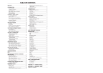
9
NOTES
The Stannah Stairiser SX
User Manual
Make sure you understand the contents of
this booklet. Keep it handy for reference.
Your Stairlift Number is:
Please quote this number on any correspondence
Your local Stannah Service Office
If your Stairlift fails to operate and BEFORE contacting the
Service Office, please read page 18 of this User Handbook.
This can save time and also save you the cost of an
unnecessary service call.
06/01/12/L:\Tech documents\Stairiser SX\Stairiser SX user manual 06.01.12.pub
Part number 4000508
24
1
9
NOTES
Your Stannah Guarantee
Stannah Lifts Ltd are proud to have secured British Standards BS
EN ISO 9001 Quality Assurance Certification and are pleased to
guarantee the whole of our materials and workmanship for a
period of twelve months from completion of installation and
handover of the lift to you on the following conditions;
•
That you enter into a proper service contract with our sister
company Stannah Lifts Service Limited. As in the motor car
industry, your new lift must be properly serviced and
maintained to keep it working at its very best.
•
Should any defect in workmanship or material become
evident within the twelve month period, we undertake to
repair or replace the defective part, as soon as possible
during our normal working hours (Monday to Thursday
8.00am to 4.45pm, Friday 8.00am to 3.45pm.).
•
Should attendance be required outside normal working
hours, it will be subject to a reasonable excess charge. The
address and telephone number of your nearest Service
Branch will be given on the “Completion Notice” Which you
should sign prior to handover of the lift to you.
•
The guarantee does not cover repairs, replacements or
adjustment which may be required as a result of ordinary
wear and tear, wilful or accidental damage, misuse, neglect
or any other cause beyond our control.
•
That all outstanding monies have been paid to us.
STANNAH LIFTS LIMITED
Anton Mill, Andover, Hampshire SP10 2NX
Tel: 01264 339090 Fax: 01264 337942
www.stannah.co.uk
2
23
9
NOTES
CONTENTS
PAGE
Your Stannah Guarantee
2
1
Introduction
4
2
Pictorial View
5
3
Operating Instructions
6
4
Emergency Operation
11
5
Safety Features
13
6
General Stairlift Care Procedures
15
7
Trouble Shooting Guide
16
8
Optional Extras
18
9
Notes
19
NOTE: Whilst every effort has been made to
ensure the clarity and accuracy of this handbook, we
cannot be held responsible for damage or injury
resulting from negligence or misuse of this Stairlift.
22
3
1
INTRODUCTION
9
NOTES
This users handbook is to help provide an understanding of correct
and safe use of The Stannah Stairiser.
It is important that you arrange for the lift to receive regular
inspection and servicing by a competent person at intervals not
exceeding six months, after the 12 months guarantee period.
Failure to ensure servicing is carried out could lead to unreliable or
unsafe operation.
For all enquiries regarding servicing, please contact your local
Stannah Service Office at the address given on page 1 of this
booklet.
A Service Log Card supplied by the Service Office will be
completed after each service visit.
As requested by the European Legislation On Machinery
Regulations, the following maximum noise emission has been
measured at a distance of 1 metre from the stairlift carriage:
Running
55 dBA
Owing to our policy of continual product development, we reserve the right to alter
specifications and dimensions without prior notice. At the date of publication this manual was
up-to-date and should there be any significant differences we will endeavour to advise you
with an addendum.
4
21
8
2
OPTIONAL EXTRAS
Hand held attendant control station
PICTORIAL VIEW
PLEASE NOTE:
The attendant control
station plugs into the
carriage control panel. The
attendant has sole control of
movement of the carriage to
assist the carriage user.
The external appearance of your Stairlift may differ slightly from
that shown below.
Carriage
Control
Station
Barrier Arms
Upper Landing Control
Station
Rail
Battery
Back-up
Box
Carriage
When unplugged, all normal
services with landing and carriage
controls are resumed.
Downhill
Platform
Ramp
Seat
Isolation
Key
Switch
Platform
Mains Power
Switch
RCD Unit
Uphill Platform
Ramp
Note: Stairlift shown with optional seat & Battery Back Box
20
5
3
OPERATING INSTRUCTIONS
WARNING - Before using your Stairlift, please
ensure that you read and familiarise
yourself with these instructions.
7
TROUBLE SHOOTING GUIDE
FAULT
CURE
No power to lift and no indicator
lights illuminated.
The safety gear has engaged.
Call Service Office.
Intended Use of the Stairlift
•
The Stairlift must not be overloaded. The maximum rated load is
displayed on the carriage load plate and on the fold down seat.
•
The Stairlift is designed only for the transportation of an
independent person with impaired mobility either seated in a
wheelchair or on the fold down seat provided.
•
The Stairlift is not designed for use by standing passengers or for
the carrying of goods or animals of any kind.
•
When travelling on the Stairlift, ensure that the wheelchair is
aligned with the platform before mounting and the brakes are
applied before the Stairlift moves.
•
Children should not be allowed to tamper or play with the Stairlift.
Joyriding can be dangerous. For added safety, always fold the
platform when not in use and turn the key switch to the ‘off’
position at both landing control stations and remove the key.
•
Check that pets or any other obstructions are not in the way
before using the Stairlift.
•
The seat provided should be used by all passengers who are not
seated in a wheelchair. The seat should be manually lowered
before use and manually raised after use.
NOTE - The Stairlift is only ready to travel when red
LED indicator on the carriage control panel is
illuminated. This indicates all mains supply switches
and safety circuit switches are set to the “on”
position.
WARNING - Power Supply Failure
If people who cannot use the stairs unaided are likely
to be alone in the premises, we recommend the
installation of an alarm system, so that in the event of a
power supply failure help can be summoned.
6
19
3
7
TO OPERATE THE STAIRLIFT USING
THE LANDING CONTROL STATIONS
TROUBLE SHOOTING GUIDE
If your Stairlift fails to operate check the following list before contacting
your local service office - it could save you time and the cost of an
unnecessary service call:
FAULT
CURE
Mains power switch is in the OFF
position.
Switch mains power to ON
position.
Mains fuse has “blown”
Replace 13 amp fuse in the mains
(confirmed by loss of light on mains power switch.
power switch).
Residual Current Device (RCD)
mounted adjacent to mains switch
has tripped
(Confirmed by loss of red indicator
on RCD unit and carriage).
Reset by pressing the green reset
button on the unit.
NB If the RCD repeatedly trips call Service Office.
•
Insert and turn the key to turn on the power to the landing station
(indicated by the green light).
•
To unfold the stairlift, press the ‘unfold’ button maintaining constant
pressure until the stairlift is fully unfolded.
•
To move the stairlift, press the ‘up’ or ‘down’ button. Maintain
constant pressure on the button, the barrier arm will fold down and
then the stairlift will move in direction required.
•
To stop the stairlift at any time, release the button. To re-start, wait
2 seconds then re-apply constant pressure to the direction button.
•
The stairlift will stop automatically at the top or bottom of the stairs.
•
To fold the stairlift, press the ‘fold’ button maintaining constant
pressure until the stairlift is fully folded.
Emergency Stop switch on carriage Free emergency stop switch to
control station stuck in position.
“ON” position.
(Confirmed by loss of light on
carriage control station).
An isolation keyswitch fitted in to
the mains supply is set to “OFF”
position.
(Lift does not function).
Insert key and rotate 90° clockwise
to “ON” position.
Keyswitch on landing control
station set to “OFF” position.
(Landing controls do not function).
Insert key and rotate 45° clockwise
to “ON” position.
(Green indicator light on)
The pressure sensitive safety
surfaces on the stairlift platform
have sensed an obstruction.
Remove any obstructions, check
that the pressure sensitive safety
surfaces return to the unobstructed
position and are operating “freely”.
Push to call or
send the platform
Push to fold
platform
Keyswitch for
Power on or off
To landing
control
station
Push to unfold
platform
Power
Indicator light
(green)
Landing control station
18
7
3
TO OPERATE THE STAIRLIFT USING
THE CARRIAGE CONTROL STATIONS
•
•
6
The Stairlift is ready to operate when the green-on indicator is
illuminated on the carriage control station and the platform has been
unfolded.
Push the joystick in the required direction of travel and maintain
constant pressure. The stairlift will begin to move once both barrier
arms are lowered.
•
The stairlift will stop immediately the joystick is released or the
emergency stop button pushed.
•
There is a 2-second time delay before the Stairlift can resume
operation after stopping.
•
The Stairlift will stop automatically at the top or bottom of the stairs.
•
An audible alarm will sound when the ‘alarm’ button (yellow) is
pressed. Release the button to stop the alarm.
GENERAL STAIRLIFT
CARE PROCEDURES
External Stairiser
Note:- Owners of the external Stairiser should ensure the lift is
tested for at least 4 journeys once a week.
A cover is provided to help protect the carriage controls from the
weather elements when not in use.
Emergency stop
button
Green power
on indicator
Audible alarm
button
Direction of travel
joystick
Carriage control station
NOTE - The stairlift is only ready to travel when the
red, power-on indicator is illuminated on the carriage
control station.
8
17
6
GENERAL STAIRLIFT
CARE PROCEDURES
Cleaning
Paint Finishes:
These should be cleaned with a soft cloth using an
aerosol type of furniture polish.
Plastic covers:
These should be cleaned with a soft cloth using soapy
water.
Aluminium rail:
This should be cleaned with a soft cloth using soapy
water.
Carriage handrail: This should be cleaned with a soft cloth using soapy
water.
3
FOLDING OPERATIONS WITH THE
STAIRLIFT AT THE LOWER LANDING
Ensure the Isolation keyswitch on the landing
is set to the on position.
Insert and turn the key in the landing station
control station to turn on the power.
1. To fold the Stairlift
Press the “fold”button on the
landing control station
maintaining pressure until the
stairlift is fully folded.
NB Never use abrasives or solvents to clean the Stairlift decor.
2. To unfold the Stairlift
Press the “unfold”button on
the landing control station
maintaining pressure until the
stairlift is fully unfolded,
enabling the user to embark.
Ensure that the barrier arm is
fully unfolded.
DISMANTLING/REMOVAL OF STAIRLIFT
You should not attempt to dismantle any parts of the
stairlift. Such work should be entrusted only to
competent personnel with relevant expert knowledge
and training.
Advise any malfunctions of the lift operation to the Stannah Service
Office or to our service personnel when they are next in
16
3. To move the Stairlift to the
upper landing using the
carriage controls
Operate the joystick in the
direction of travel. The lower
barrier arm will unfold.
Maintain pressure on joystick
to travel up. On arrival at the
upper landing continued
pressure on the joystick will raise
the upper barrier arm, enabling
you to disembark.
9
3
FOLDING OPERATIONS WITH THE
STAIRLIFT AT THE UPPER LANDING
Ensure the Isolation keyswitch on the landing
is set to the on position.
Insert and turn the key in the landing station
control station to turn on the power.
1. To fold the Stairlift
Press the “fold” button on the
landing control station
maintaining pressure until the
stairlift is fully folded.
5
SAFETY FEATURES
2
Safety Gear
The Stairlift is fitted with a safety gear which will lock the carriage
onto the rail if the stairlift overspeeds. If the safety gear does
operate, it should be released only by an authorised service
engineer. Please note, in this instance the Stairiser will not
emergency lower.
3
Residual Current Device (RCD)
This unit is mounted adjacent to the mains power switch and
protects against electric shock from the mains power supply.
Indicator shows red
when RCD is on.
2. To unfold the Stairlift
Press the “unfold” button on
the landing control station
maintaining pressure until the
stairlift is fully unfolded,
enabling the user to embark.
Ensure the barrier arm is fully
unfolded.
3. To move the Stairlift to the
lower landing using the
carriage controls.
Operate the joystick in the
direction of travel. The upper
barrier arm will unfold.
Maintain pressure on joystick to
travel down. On arrival at the
lower landing, continued
pressure on the joystick will raise
the lower barrier arm, enabling you
to disembark.
10
Reset Button (Green)
Test Button (Blue)
NOTE - Check the operation at least every three
months. To do this, press the button marked
“Test” and the Residual Current Device (RCD)
should trip.
To reset the unit, press in the “Reset” button.
15
5
SAFETY FEATURES
Your Stairlift has many built-in safety features to protect the user and
other occupants within the premises. Some of these integral features
are listed below.
1
Pressure Sensitive Surfaces
Touch sensitive surfaces are provided on the end ramps and
underside of the platform. These stop the Stairlift automatically
if they meet an obstruction during travel. To remove any
obstructions, reverse the direction of travel for a short distance
by pressing the “up” or “down” landing push button control as
appropriate.
4
EMERGENCY OPERATION
This procedure must only be undertaken in an emergency due to loss
of power to the lift and must only be undertaken by authorised
personnel with the lift under constant surveillance.
To hand wind the Stairlift, proceed as follows:
1
Switch off the mains electrical supply to
the stairlift and remove the main supply
fuse from the main supply switch so that
there is no possibility of the carriage
being operated.
2
Remove the plastic cap positioned
above the carriage controls and insert
the hand winding tool through the hole in the carriage top panel.
3
Locate the hand winding tool in the boss and rotate the hand wheel in
the required direction until the platform is approx. 20mm from floor
level. Note: the lift may be damaged should the platform be allowed
to proceed beyond this point.
4
Remove rubber bung from side of the lift the barrier arm needs to be
raised. Using the hand winding wheel locate in hole and push down,
at the same time push the barrier arm towards the carriage and lift
arm up. Release passenger. To Lower arm repeat procedure.
Pressure Sensitive
Safety Surfaces
14
11
4
5
EMERGENCY OPERATION
Once the passenger has been released, isolate the unit via the mains
keyswitch to prevent further use. Manually lift the other barrier arm
and the platform and secure in the upright position using the strap
provided and warn any potential users not to release the strap since
the platform is no longer connected to the drive.
Note: No attempt should be made to operate the lift with the
strap in place.
4
EMERGENCY OPERATION
This procedure must only be undertaken in an emergency due
to loss of power to the lift and must only be undertaken by
authorised personnel with the lift under constant surveillance.
Battery powered Winding (optional)
To power wind the Stairlift, proceed as follows:
WARNING - The carriage must never be run with
the hand or power winding tool in position
otherwise injury could result. The tool must
always be removed after hand winding. If the
Stairlift will not run, the unit should then be
checked by your local Service Office before the
Stairlift is returned to service (unless stoppage
was caused by an obvious fault see page 16).
12
1
Switch off the mains electrical supply to the stairlift and remove the
main supply fuse from the main supply switch so that there is no
possibility of the carriage being operated.
2
Remove the plastic cap positioned above the carriage controls and
insert the power winding tool through the hole in the carriage top
panel. Insert the jack plug in to the socket on the carriage.
3
Locate the powered winding tool in the boss and press the button on
the box with constant pressure until the platform is approx. 20mm
from floor level. Note: the lift may be damaged should the platform be
allowed to proceed beyond this point.
4
Using the power winding tool follow step 4 on page 11.
5
Once the passenger has been released, isolate the unit via the mains
keyswitch to prevent further use. Manually lift the other barrier arm
and the platform and secure in the upright position using the strap
provided and warn any potential users not to release the strap since
the platform is no longer connected to the drive.
Note: No attempt should be made to operate the lift with the
strap in place.
13