1
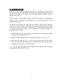
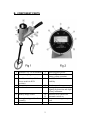
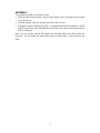
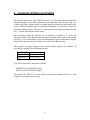
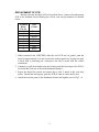
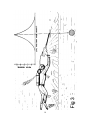
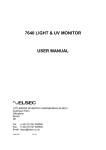
2000 UNDERWATER
METAL DETECTOR
USER MANUAL
LITTLEMORE SCIENTIFIC ENGINEERING (ELSEC)
Gutchpool Farm
Gillingham
Dorset
UK
Tel:
(+44) (0)1747 835550
Fax: (+44) (0)1747 835552
Email: [email protected]
2000.DOC
2
CONTENTS
A. INTRODUCTION ____________________________________________________ 1
B. COMPONENT PARTS ________________________________________________ 2
ASSEMBLY __________________________________________________________________ 3
C. OPERATING INSTRUCTIONS _________________________________________ 4
TESTING ON LAND: __________________________________________________________ 4
D. USE IN THE WATER _________________________________________________ 5
ADJUSTMENT OF BUOYANCY: ________________________________________________ 5
E. CHARGING INTERNAL BATTERIES____________________________________ 6
F. DETECTION DISTANCES _____________________________________________ 7
G. MAINTENANCE _____________________________________________________ 8
REPLACEMENT OF MODULES ________________________________________________ 8
REPLACEMENT OF BATTERY PACK __________________________________________ 8
REMOVAL OF PRINTED CIRCUIT BOARD (PCB)________________________________ 8
REPLACEMENT OF PCB ______________________________________________________ 9
COIL REPLACEMENT FOR 2000 METAL DETECTOR___________________________ 10
H. EXTRAS AND SPARES ______________________________________________ 13
PRINTED 13-Oct-06
3
A. INTRODUCTION
The Elsec Underwater Metal Detector Type 2000 is the product of many years of
development in the field of metal detection equipment. Handling characteristics of the
detector are excellent at all depths due to the slight positive buoyancy which is
inherent in the design.
Elsec have gone to great lengths to reduce the amount of metal used in the detector
housing, thereby minimising the possibilities of corrosion, irrespective of the
operating environment.
The design of the detector has many innovative features which include automatic
switch-on when the detector is submerged, the ability to compensate for salt water
conductivity, operation within high concentrations of metallic deposits and the option
of variable detector head position. Diver indication of located metal objects is
presented by three methods:
a) An illuminated analogue meter, which can be calibrated, for calculating the depth
of bury of a known object (Fig. 2-13).
b) High power light emitting diode, to assist when visibility is poor (Fig. 2-11).
c) Bone conductor earphone (Fig. 1-5), worn over the diving hood and held in place
by the face mask band this earphone gives a progressive frequency change of blips
depending on the proximity of detected metal.
The instrument is supplied with rechargeable nickel cadmium batteries giving a
minimum operational time of 10 hours.
1
B. COMPONENT PARTS
1
2
Detector Coil - 28 cm diameter
Transit coupling
9
10
3
11
4
5
Run/Reset switch (solid line
shows switch in RUN
position).
Face plate
Bone conductor
6
Battery charge socket
7
Battery housing and handle
assembly
Face plate screws
1415
16
8
12
13
2
Read-out panel screws
Green LED for Reset and
battery voltage operation
Red LED for detection in poor
visibility
Read-out panel
Analogue meter with internal
lighting for detection and depth
of bury calibration.
Stainless Steel contacts for
automatic switch on.
Setscrews securing battery
pack
ASSEMBLY
To assemble the staff to the detector body:
1. Hold the staff in the required position with respect to the coil for the type of search
to be carried out.
2. Feed the surplus cable out through the staff at the coil end.
3. Tighten the transit coupling ring (Fig 1-2) by hand until locked in position. As this
joint does not have to be watertight no special tools are required and hand pressure
will be sufficient.
Note: On no account should the domed nut through which the cable passes be
loosened. Do not rotate the shaft with respect to main body as this will twist the
cable.
3
C. OPERATING INSTRUCTIONS
TESTING ON LAND:
Having charged the batteries as detailed in Section E it is recommended that the
detector is tested on land before use in the water. The following procedure is
suggested:
1. Hold the detector away from any metal objects.
2. Switch on the detector by bridging the two stainless steel contacts on the underside
of the detector body (Fig. 1-14/15). This is achieved by wetting the thumb and
index finger and placing them across the two contacts, maintain this position
throughout the remainder of the tests.
3. When switched on the meter will take up an arbitrary reading which will require
the unit to be reset.
4. To reset the detector turn the RESET/RUN switch (Fig. 1-3) to the Reset position,
when reset the Green LED (Fig. 2-10) on the front panel will be illuminated. This
operation also checks that the batteries are charged. The meter needle should now
read between 0 and 1, the Red LED should flash at approximately once per second
and the bone-conductor should click at the same rate.
5. After reset return the Reset/Run switch to the Run position (the direction of
rotation is not important).
6. Move the detector towards a metal object until the meter reads full scale. Leave
the detector in this position and reset once more. When returned to the Run
position the meter should return to the 0-1 position; now move away from the
metal object and note that the meter needle goes off-scale to the left.
7. If all the above tests are correct switch off the unit by removing your fingers from
the studs, the detector has now been tested for normal use.
Note: If more than one metal detector is used close to each other they may interfere.
This effect can be seen over 5M away with large coils.
4
D. USE IN THE WATER
Take the instrument down to the search area and level off at the height above the
seabed where you require to operate. Due to air bottles, compass and the conductivity
of the water the unit will require compensation to back-off these effects. This is
achieved by operating the RESET/RUN switch from the Run position to Reset, noting
that the Green LED is illuminated, then returning to the Run position.
For minimum fluctuation in meter reading try and swim at a constant height above the
seabed, if this is not possible and the meter slowly changes use the Reset/Run switch
as above to compensate; remember in each case to return the switch to the Run
position.
When the coil passes over a metal object the reading on the meter, the flash rate of the
Red LED and the blip rate of the bone conductor will all increase.
Should the sensed object be very large and drive the meter off-scale then the diver
must raise the height of the coil until the reading comes back on scale. To pinpoint
the exact position of an object move the coil forward and backward in a straight line,
stopping at the maximum reading. Now move left to right at right angles to the
original line and note the maximum reading on the meter, the object will now be
directly on the axis of the detector coil (see Fig.3).
ADJUSTMENT OF BUOYANCY:
The instrument, when it leaves the factory, is just buoyant in freshwater. A lead
weight is provided within the handle of the instrument and this may be removed or cut
to size, so that the resultant buoyancy suits the user. If the lead weight is removed
entirely, the instrument will be decidedly buoyant. Access to the lead weight can be
achieved by removing the plastic end cap from the handle.
Note: If more than one metal detector is used close to each other they may interfere.
This effect can be seen over 5M away with large coils.
5
E. CHARGING INTERNAL BATTERIES
The batteries fitted to the Type 2000 Detector are 2.5 AH nickel cadmium which are
charged through a 2 pin socket mounted on the underside of the detector (Fig 3-6).
Connect the battery charger lead to a suitable supply and attach the other lead to this
socket. When the battery pack is completely discharged it will require 14 hours to
obtain maximum capacity. However, it is good practice to charge the system after use
for 1 1/2 times the total time in the water.
After charging switch the detector on as described in Section C-2, rotate the
Reset/Run switch to the Reset position and check that the Green LED on the readout
panel (Fig. 2-10) is illuminated; if it is not illuminated the power to the battery charger
may not be connected correctly. Return the switch to the Run position.
Three options of input voltage for the external battery charger are available, all
providing a constant 250 mA charging current
Type 2009/240 240v AC +/- 10%
Type 2009/115 115v AC +/- 10%
Type 2009/12 12 to 15v DC
Type 2009/12 must be connected as follows:
BROWN lead to POSITIVE supply
BLUE lead to NEGATIVE supply
The input of the 2009/12 is reverse polarity protected; no damage will occur to the
charger if it is connected incorrectly.
6
F. DETECTION DISTANCES
The detection distance for a metal object depends on:
a) Its size
b) Its shape and orientation with respect to the search coil.
c) The type of metal or alloy present.
In general the better the conductivity of the metal the greater the detection distance for
a given size object. For example, pure gold, copper or silver will be detected at a
greater range than bronze or nickel alloys, whilst aluminium and lead fall between
these two groups. Iron or steel is also readily detected due to its magnetic properties.
It is not possible to obtain quite as great a detection range in sea water as in fresh
water or on land. This is because sea water is an electrical conductor and this absorbs
the signals to some extent. However, the 2000 instrument offers the best solution so
far to this problem and has a superior range on objects of all sizes. For example, a 2p
piece will be detected at distances up to 30 cm and large objects such as cannon or
iron pipes at distances up to 3 metres.
Although the instrument is ruggedly constructed it should be treated as a piece of
scientific apparatus and provided the maintenance and operational instructions are
adhered to the detector should give long and trouble-free service.
7
G. MAINTENANCE
When diving has finished the detector should be washed in clean fresh water, with
particular attention to the battery charger socket and stainless steel switch contacts
(see Fig. 1 - 6,14,15). After washing, dry the unit completely and store in as dry an
environment as possible. Unless absolutely necessary do not part the staff from the
coil assembly as continual flexing of this joint will fracture the cable.
REPLACEMENT OF MODULES
In the unlikely event that the battery pack or electronic control printed circuit board
should fail, both modules can be replaced with the minimum of equipment and
specialist knowledge. It is most important, however, that the detector housing is not
opened except under cover as any ingress of sea-spray or moisture will affect the
operation of the instrument.
REPLACEMENT OF BATTERY PACK
1. Remove 8 off screws (Fig 1 -16).
2. Hold the detector body in one hand and the handle in the other, with a constant
pull, gently separate them. Inside the housing is an in-line connector, part this and
remove the old battery pack. Before fitting the replacement pack ensure that the
"O" ring is clean and greased. To refit, reverse the above procedure, tightening the
screws evenly.
REMOVAL OF PRINTED CIRCUIT BOARD (PCB)
1. Unscrew both Readout Panel Screws (Fig. 2-9) and remove panel (Fig. 2-12).
There is sufficient cable to allow the panel to be withdrawn approximately 10 cm.
2. The end of the PCB is now visible. Holding both sides of the PCB, gently pull out
the board until the socket connecting the readout panel to the PCB can be
removed. This is achieved by flexing outwards the thin plate directly in front of
the plug and lifting the socket free.
3. Continue to pull the PCB until it is free from the detector housing.
4. Disconnect the wires from the terminal block at the end of the PCB.
8
REPLACEMENT OF PCB
Having removed the faulty PCB as described above, connect the replacement
PCB to the terminal block following the colour code and pin numbers as detailed
below:
Terminal
Block
Pin No
1
2
3
4
5
6
7
8
Wire
Colour
Green
Orange
Brown
Blue
Red
Inner
Outer
Black
1. When connected and CHECKED, slide the new PCB into its guides, push the
board in approximately 5 cm and connect the readout panel into its plug (the plug
is fitted with a polarising pin; connection can only be made with the correct
orientation).
2. Continue to push the assembly into the housing until the front edge of the PCB is
level with the front end of the small aluminium bracket.
3. Rotate the Reset Run switch and ensure that a click is heard as the reed relay
makes. Should this not happen, push the PCB in 2mm at a time until it does.
4. Attach the read-out panel to the aluminium bracket and tighten screws (Fig 2 - 9).
9
COIL REPLACEMENT FOR 2000 METAL DETECTOR
This section is designed to enable users to replace the coil assembly. Please follow the steps
outlined closely. These are quite difficult procedures and should only be attempted if the user
is confident of his/her ability. If in doubt send the unit back to the manufacturer.
Note that this section does NOT apply to the type 2001,
which has a plug in coil.
I.
REMOVE COIL
1. Remove clear plastic faceplate and undo the two small screws on the engraved meter
panel.
2. Withdraw the meter and carefully pull the printed circuit board from the body of the unit
far enough to allow access to the terminals on the rear of the board.
3. Disconnect the wires on terminals 6 and 7 which are the coil connections.
4. Undo the coupling of the coil staff and feed the coil cable into the staff from the coil end
to expose the domed nut at the front end of the detector body.
5. Undo the domed nut to reveal the sealing O-ring. Cut the coil cable end inside the body to
remove the soldered joints and withdraw the cable.
Note If the bolt in the nose of the unit requires replacement then go to Section III below,
otherwise continue with Section II (Reassembly) below.
10
II.
REASSEMBLY
1. Check that the O-ring and domed nut are on the new coil cable.
2. Apply a little grease to the O-ring and thread the cable through the hollow bolt. Ensure
that the cable is fed above the aluminium plate inside the body and leave enough cable
outside the body to allow the joint in the staff to be broken for transit.
3. Tighten the domed nut until it rests on the plastic locking nut on the hollow bolt.
4. Prepare the end of the cable by soldering the short white wire supplied to the screen of the
cable.
5. Cover the joint with the heat shrink tube supplied and use a hair dryer or other source of
heat to shrink the sleeve onto the cable.
6. Connect inner of the cable to pin 6 and screen to pin 7 of the connector.
7. Slide the printed circuit board into the guides taking care to feed the wires into the space
above the battery compartment. ( A piece of bent wire inserted below the board will be
necessary.)
8. Position the board so that it just clears the meter and check that the board is correctly
positioned by rotating the reset knob and ensuring that the reed switch on top of the board
is operating.
9. The reed switch will make a small clicking noise as it makes and breaks.
10. Replace the meter and give the unit a check by shorting the screws each side of the
charging socket and operating the reset knob before replacing the faceplate.
11
III.
HOLLOW BOLT REPLACEMENT
Note This is a difficult operation and should not be attempted unless absolutely necessary.
1. Remove the covering of the four screws in the side of the body (either plastic caps or
silicon rubber) and undo the screws with O-ring seals which releases the aluminium block
to which the board was attached, and remove the block.
2. Remove the plastic locking nut which was behind the domed nut. It is necessary to
fabricate a long tube spanner to remove the hollow bolt from the inside of the nose of the
body.
3. Remove the bolt and replace with a new one taking care to keep the O-ring clean. Note
The O-ring should not be greased as this will allow the ring to be squeezed out of
position.
4. Replace the locking nut on the outside of the hollow bolt and feed the new coil cable
through the hollow bolt.
5. Replace the aluminium block below the cable. When replacing the screws to secure the
aluminium block smear the O-rings with silicone rubber to ensure a complete seal.
6. Replace the caps over the screws or fill the cavities with silicone rubber.
7. Continue with section II-1. above.
12
H. EXTRAS AND SPARES
A recommended spares pack can be obtained, this comprises a complete printed
circuit board and battery pack, both are replaceable in the field (see Sections G2 and G
4).
13
14