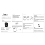
1
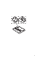
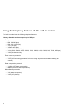
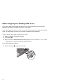
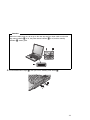
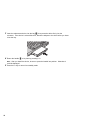
Part Number: 04P4540 ThinkPad A20 Supplement to user's manuals The basic manuals for your ThinkPad A20 computer are the online user's manual, ThinkPad Assistant, and the user's reference (P/N 04P4220). This supplement presents additions and updates to the information in those user's manuals. Each of the following sections replaces the corresponding section in the user's manuals, or adds further information. “Installing Windows 2000” on page 2 “Creating a hibernation file” on page 3 “Using the card stopper for the Mini-PCI Card” on page 4 “Using the telephony features of the built-in modem” on page 6 “Enabling the TrackPoint” on page 7 “Using the DVI monitor” on page 8 “Warm-swapping the Ultrabay 2000 device” on page 10 “Attaching the ThinkPad Dock” on page 13 “Troubleshooting” on page 15 “Notices” on page 16 Copyright IBM Corp. 2000 1 Installing Windows 2000 To install Windows 2000 and its software on your computer, do as follows: 1 2 Start the system. Insert the Windows 2000 Professional CD in the CD-ROM or DVD-ROM drive. Follow the instructions on the screen. After you install Windows 2000, you will need to install the application software, which is provided on the Software Selection CD for Windows 2000. To install an application, do the following: 1 Insert the Software Selection CD for Windows 2000 in the CD-ROM or DVD-ROM drive. A list of the programs appears. 2 Install one program at a time. Select each one in turn, and follow the instructions on the screen. The latest information on these applications is posted on the Web site: http://www.ibm.com/thinkpad/ 2 Creating a hibernation file Attention When you start the system with the Hibernation Utility for Standalone Boot diskette, be sure not to choose the Create Partition option. If you do so, your hard disk will quit working, and you will have to take it to an IBM reseller or marketing representative for reformatting. Thus all of the data on the hard disk will be lost. The following instructions are for those using operating systems other than Windows 2000. If you want to suspend operation but keep your work exactly as it is, so that you can resume operation at the same point later, you can put your computer in hibernation mode. To use the hibernation mode, you need to create a hibernation file with ThinkPad Configuration Program. This file can be created on a single-partitioned or multiple-partitioned hard disk drive, and is subject to the following restrictions: It must be created on the primary hard disk drive. All partitions must be formatted before you create the hibernation file. The partitions must be formatted in either FAT16 or FAT32; you cannot use NTFS, the default file system for Windows NT. 3 Using the card stopper for the Mini-PCI Card The Mini-PCI Card is held in place by a card stopper shown in the drawing below. Following is the overall procedure for replacing the Mini-PCI Card. For more detailed drawings with text, see the online user's guide. 1 2 3 Turn off the computer; then disconnect the ac adapter and all cables from the computer. 4 5 Release the card stopper by lifting it .1/. 6 7 8 Disconnect the cable from the card .3/; then remove the card .4/. 9 Pivot the card until it snaps into place. Make sure that the card is firmly fixed in the slot and does not move easily. Remove the battery pack. Loosen the screw on the Mini-PCI Card slot cover at the bottom of the computer; then remove the cover. Press out on the latches on both sides of the socket at the same time until the card moves up .2/. Connect the cable to the new Mini-PCI Card. Align the contact edge of the Mini-PCI Card with the corresponding socket of the computer, at an angle of about 45 degrees. Insert the Mini-PCI Card into the socket. 10 Fasten the card stopper by pressing it down. Make sure that both latches snap into place. Also make sure that the arrow mark à on the stopper points toward the card connector. 11 Align the tabs of the Mini-PCI Card slot cover with the corresponding slots; then press the cover flat. 12 13 Tighten the screw of the cover. 4 Put the battery pack back in place, and turn the computer on. 5 Using the telephony features of the built-in modem The built-in modem has the following telephony features: Industry Standard modem support up to 56 Kbps: Data protocols – – – – – – – Bell 103 (300 bps) Bell 212A (1200 bps) V.21 (300 bps) V22bis (2400 bps) V.34bis (33600, 31200 bps) V.34 (28800, 26400, 24000, 21600, 19200, 16800, 14400, 12000, 9600, 7200, 4800 bps) V.90 (downstream only) Error correction protocols – MNP2-4 (Microcom error correction) – V.42 (error-correcting procedures for DCEs using asynchronous automatic dialing and control) Data compression protocols – V.42bis (DCE data compression) – MNP5 (Microcom data compression) Miscellaneous protocols – V.8 (startup sequence) – V.90 (video phone) 6 Industry standard fax support up to 14.4 Kbps: Fax protocols – – – – V.21 Ch 2 (300-bps fax) V.17 (up to 14.4-Kbps fax) V.29 (9600-bps fax) V.27ter (4800-bps fax) Computer telephony function support: DTMF and pulse dialing Detecting DTMF digits received from the phone line Call progress monitoring An auto-dialing feature Telephony API (TAPI) support through Windows 98 and Windows 95 Enabling the TrackPoint The TrackPoint is designed to work simultaneously with a mouse that it compatible with the IBM PS/2 Miniature Mouse. By default, the TrackPoint is set to Auto-Disable. When this setting is in effect, the TrackPoint is disabled automatically when a mouse is connected to the external-input-device connector. To enable the TrackPoint so that it will work simultaneously with a mouse, do the following: 1 2 3 4 5 Click Start → Settings → Control Panel. The Control Panel window appears. Double-click the ThinkPad Configuration icon. The ThinkPad Configuration window appears. Click the TrackPoint button on the left side of the window. On the dropdown menu, click Enable. Click OK. 7 Using the DVI monitor If you have a model A20p computer, you can use either of the following Digital Visual Interface (DVI) monitors through the DVI connector of an expansion unit—either a ThinkPad Dock or a ThinkPad Port Replicator: IBM T85D 18-inch TFT LCD Digital Color Monitor (DVI model) IBM T55D 15-inch TFT LCD Digital Color Monitor (DVI model) Note: Before you attach the DVI monitor, make sure that the computer is attached to the expansion unit and the system works properly. To attach the DVI monitor, do as follows: 1 2 Turn off the computer. 3 Connect the DVI monitor to the DVI connector on the rear of the expansion unit, and then connect the monitor to an electrical outlet. 4 Turn on the DVI monitor and the computer. The system starts. Insert a small flathead screwdriver or a similar tool into the slot at the upper left of the cover on the DVI connector, and pry the cover off. If the computer output does not appear on the DVI monitor, do the following: 1 2 3 4 5 6 7 8 Click Start → Settings → Control Panel. Double-click Display. The Display Properties window opens. Click the Settings tab. Click Advanced... Click the Displays tab. The FPD option appears. Click the button on the left side of the FPD button. The FPD option is enabled. Click Apply. The computer output appears on the DVI monitor. Considerations for attaching a DVI monitor Connect the DVI monitor to the expansion unit, and turn it on, before you turn on the computer. Otherwise the system cannot recognize that the monitor is connected. If the option for enabling the DVI monitor in the Display Properties window does not appear, try closing the window and opening it again. If the option still does not appear, make sure that the connector of the monitor is attached firmly, and repeat the procedure for attaching the monitor. If you see a DVD movie on the DVI monitor, the monitor needs to be set as the primary display. 1. Open the Display Properties window as described on page 8. The FPD option appears. 2. Make sure that the button on it shows Primary. If it does not, click the button to change it to Primary. 3. Click Apply. You cannot use Fn+F7 to switch between the computer LCD and the DVI monitor. If you use the screen expansion function, the DVI monitor needs to be set as the primary display. 1. 2. 3. 4. Open the Display Properties window as described on page 8. The FPD option appears. Click the button that shows FPD. The Attribute tab appears. Click the Screen expansion button. Click Apply. The display output does not appear on the DVI monitor during the startup of the system. It appears as soon as the desktop of the system comes up. 9 Warm-swapping the Ultrabay 2000 device If you want to replace the Ultrabay 2000 device of your computer with another of the devices described in the online user's guide, you can do a warm swap. To do a warm swap is to remove, connect, or reconnect a device while the computer is in standby mode. As configured at the factory, your computer is enabled for warm swapping. To check whether warm swap is enabled, do as follows: 1 2 3 Start the ThinkPad Configuration Program. Click Device Bay. Make sure that the Enable IDE device warm swap check box is selected. If it is not, select it, and restart your computer to make the change effective. To do a warm-swap, do as follows: 1 10 Slide the bay-latch .1/ to pop out the handle. Attention When the handle pops out, do not go to the next step until you have made sure that the bay status indicator .1/ is off, the power status indicator .2/ is off, and the standby indicator .3/ shows green. 2 Pull the handle until it stops .2/; then pull out the Ultrabay 2000 device .3/. 11 3 Insert the replacement device into the bay .3/; then press the device firmly into the connector. If the device is a hard-disk drive, attach the adapter to the drive before you insert it into the bay. 4 Return the handle .4/ to its place by pressing it in. Note: After you install the device, be sure to press the handle into position. Otherwise it could be damaged. 5 12 Press the Fn key to return from standby mode. Attaching the ThinkPad Dock If you attach the ThinkPad Dock (available as an option) to your computer, this information applies to you. USB connector If you are using Windows 95, you can use only the lower USB connector of the ThinkPad Dock docking station. Installing the device driver for Windows NT 4.0 The updated procedure is as follows: 1 2 3 4 5 Turn on the computer. After Windows NT has started, click Start → Settings → Control Panel. Double-click SCSI Adapters. Click the Drivers tab. If you find either of the following drivers, remove it. Intel PIIX PCI Bus Master IDE Controller IDE CD-ROM (ATAPI 1.2)/Dual Channel PCI IDE Controller 6 7 8 9 10 11 12 If you do not find the ThinkPad PIIX4 IDE Driver, install it from the Software Selections CD. 13 14 15 16 If you are prompted to restart the system, select No. Click Add. Click Have Disk. Specify the location of the device driver in the Software Selections CD, and click OK. Select oemsetup.inf file, and click OK. Make sure that CMD PCI-0648 is selected, and click OK. When prompted for the location of the file, specify the location of the device driver in the Software Selections CD. Shut down the system, and turn off the computer. Attach the computer to the ThinkPad Dock. Turn on the computer. Note: After the device driver for the CMD IDE Controller has been installed, you can expect that each time Windows NT is started with the computer undocked, or docked with no device in the Ultrabay 2000, you will see an error message, “At least one service or driver failed 13 during system startup. Use event viewer to examine the event log for details.” You can ignore this message. Security keyhole for Ultrabay 2000 device To secure the Ultrabay 2000 device to the docking station, you lock the device release lever. There are two ways to lock it: You can use the bay device lock, which is inside the bottom cover of the docking station. You can use the security keyhole next to the device release lever. If you use this method, be sure that the bay device lock is unlocked. Whichever of these locks you use, it should always be used along with the mechanical lock. 14 Troubleshooting Error messages Problem Cause and action EMM386 Not Installed—Unable to Set Page Frame Base Address. Edit C:\CONFIG.SYS and change a line from device=C:\WINDOWS\EMM386.EXE RAM to device=C:\WINDOWS\EMM386.EXE NOEMS and save this file. CardBus Configuration Error—Device Disabled. Press F1 to go to the IBM BIOS Setup Utility. Press F9 and then Enter to load the default setting. Press F10 and then Enter to restart the system. Modem Problem Cause and action Your modem application does not work in Windows 95. Make sure that the modem is connected correctly. Make sure that no exclamation point ! appears to the left of the Lucent Win Modem in the Device Manager window. If the ! is there, there might be a system resource conflict with the other port. ThinkPad Dock Problem Cause and action The PC Card, a PCI card, or a device in the Ultrabay 2000 installed in a docking station is not recognized, and the PC Card slots cannot be used. Make sure that the power cord is connected to the docking station. Make sure that the docking indicator of the docking station is on. Make sure that the computer is securely attached to the docking station. 15 Notices Notice for Australia The following notice applies when using the telephony functions: WARNING: FOR SAFETY REASONS, ONLY CONNECT EQUIPMENT WITH A TELECOMMUNICATIONS COMPLIANCE LABEL. THIS INCLUDES CUSTOMER EQUIPMENT PREVIOUSLY LABELLED PERMITTED OR CERTIFIED. Notice for Users in New Zealand The modem in this ThinkPad is set up for Tone Dialing. Users should only select Pulse Dialing if they are connecting to the Telecom NZ network via a PBX or other systems which requires Pulse Dialing. Pulse Dialing is required only for a small number of obsolescent PBX or similar systems. The grant of a Telepermit for any item of terminal equipment indicates only that Telecom has accepted that the item complies with minimum conditions for connection to its network. It indicates no endorsement of the product by Telecom, nor does it provide any sort of warranty. Above all, it provides no assurance that any item will work correctly in all respects with another item of Telepermitted equipment of a different make or model, nor does it imply that any product is compatible with all of Telecom's network services. This equipment is not capable, under all operating conditions, of correct operation at the higher speeds for which it is designed. Telecom will accept no responsibility should difficulties arise in such circumstances. This device is equipped with pulse dialling while the Telecom standard is DTMF tone dialling. There is no guarantee that Telecom lines will always continue to support pulse dialling. Use of pulse dialling, when this equipment is connected to the same line as other equipment, may give rise to bell tinkle or noise and may also cause a false answer condition. Should such problems occur, the user should NOT contact the Telecom Faults Service. This equipment shall not be set to make automatic calls to the Telecom '111' Emergency Service. This equipment should not be used under any circumstances which may constitute a nuisance to other Telecom customers. 16