1
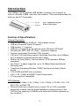
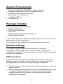
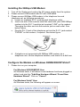
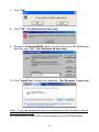
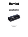
V.92 USB MODEM 56K USB Modem Fax User Manual HV92USB2 www.hamletcom.com Dear Customer, thanks for choosing an Hamlet product. Please carefully follow the instructions for its use and maintenance and, once this item has run its life span, we kindly ask You to dispose of it in an environmentally friendly way, by putting it in the separate bins for electrical/electronic waste, or to bring it back to your retailer who will collect it for free. We inform You this product is manufactured with materials and components in compliance with RoHS Directive 2002/95/CE, WEEE Directive 2002/96/CE, 2003/108/CE Italian Legislative Decree 2005/151, LVD Directive 2006/95/EC and EMC Directive 2004/108/EC for the following standards: EN 60950-1: 2001 + A11: 2004 EN 55022: 1998 + A1: 2000 + A2: 2003 EN 61000-3-2: 2000 + A2: 2005 EN 61000-3-3: 1995 + A1: 2001 + A2: 2005 EN 55024: 1998 + A1: 2001 + A2: 2003 EN 300 386: V.1.3.3: 2005 / AS/NZS CISPR 22: 2004. The complete CE declaration of conformity of the product can be obtained by contacting Hamlet at e-mail address [email protected]. The information on the importer for your country are available in the “About Us” section of the Hamlet website at www.hamletcom.com. Trademarks and changes All trademarks and company names mentioned in this manual are used for description purpose only and remain property of their respective owners. Hamlet reserves the right to revise this publication and to make changes from time to time in the contents hereof without obligation to notify any person of such revision or changes. 2 Introduction This 56Kbps Voice/Fax/Data USB Modem connects your computer to Internet, all kinds of BBS, and other fax modems. This manual describes the features, and AT Commands. Line: Telephone line jack Phone: Phone jack Features & Specifications General Description • Use AGERE Olympia SV92U2 / 1040 chipset solution • USB bus Powered/ system Powered • USB version 1.1 supports • USB ver.2.0 supports as an optional under Windows XP/Vista/7 • Windows 98, 2000, ME, XP, Vista, 7 operation supports • Pentium Host-based Controller/ CPU required • V.92 and V.90 technology present Receiving Data Rate up to 56Kbps, from a digitally connected central site modem • Modem on Hook (MoH), Fast connection, PCM upstream 48Kbps supported • Fax Class 1 modem supported, up to 14.4Kbps Data transmission/ Receiving rate • Telephone Answering Machine (TAM) Functional via Audio Sound device • V.42 LAPM and MNP error correction • V.44, V.42, V.42bis and MNP 5 data Compression • AT command set compatible DATA Modem • V.92, V.90, V.34bis, V.34, V.32bis, V.32, V.22bis, V.22 A/B, V.23, V.21, Bell 212A, and Bell 103 • Received data from a digital source using V.92 or V.90 compatible central site modem over the digital telephone network portion of the PSTN at line speed up to 56Kbps with automatic fall-back depends on line condition 3 FAX Modem • ITU-T V.17 , V.29 , V.27ter and 21 channel 2 . • TIA/EIA 578 Class 1 FAX send and receive speeds of 14400, 12000, 9600, 7200, 4800 or 2400bps VOICE / Audio Mode • TAM through the microphone / speaker interface on Audio Sound card ERROR Correction • Support V.42 LAMP, MNP 2-4 DATA Compression • Support V.44,V.42bis and MNP 5 DAA Line interface Capabilities • DTMF Tone Dial/ accurate make-break ratio Pulse Dial • Proprietary transformer-based isolation barrier • Programmable even detect for Caller-ID reception and Power Ring detection • Programmable AC/DC impedance termination for Return-Loss / Specific Countries homologations FLOW Control • Both transmit and receive fax data are buffered Data transmission over DTE is Flow controlled by XON/XOFF and RTS/CTS 4 System Requirements • • • • • • Computer with Pentium 200 MMX or higher processor Windows 98/ME/2000/XP/Vista/7 Operating System 20 MB Hard Disk free space or above Sound card for voice features 1 available USB port CD-ROM drive Package Includes The box contains the following items: • 56Kbps USB Modem • RJ11 Phone Line Cable • USB cable • Utility CD with Drivers and User's Manual • Quick Installation Guide If any of these items are missing or damaged, please contact your dealer or sales representative for assistance. The latest drivers are available on website www.hamletcom.com Hardware Setup This chapter contains detailed instructions how to install and configure the 56Kbps USB modem, as well as how to verify if your installation is correct. We recommend that you follow the steps accordingly to avoid future problems. ESD Precautions Electrostatic discharge (ESD) can damage your processor, disk drives, expansion boards, and other system components. Always observe the following precautions before you install any system component. 1. Do not remove a component from its protective packaging until you are ready to install it. 2. Wear a wrist grounding strap and attach it to a metal part of the system unit before handling components. If a wrist strap is not available, maintain contact with the system unit throughout any procedure requiring ESD protection. 5 Installing the 56Kbps USB Modem 1. Turn off the System and unplug the AC power supply from the system. 2. Please connect USB modem and PC with USB cable. 3. Please connect 56Kbps USB modem to the telephone line and telephone set, as following procedures. a. Locate an available RJ-11 modular jack telephone outlet. b. Insert one end of the modular cord that came with your USB 56Kbps modem into the RJ-11 modular jack marked “LINE” on the modem. Then plug the other end into the modular jack on wall outlet. See below Figure. c. Plug the RJ-11 jack of the telephone set into the RJ-11 jack marked “PHONE” on the modem, if required. See below figure. d. If telephone set connected with 56Kbps USB modem via a telephone cord, life the telephone handset, and check for a dial tone Configure the Modem on Windows 98/ME/2000/XP/Vista/7 1. Please turn on your computer. For Windows 98/2000/ME/XP User As Windows starts, it will detect a new hardware has been plugged or added, and start the "Add New Hardware Wizard / Found New Hardware Wizard". Click on "Cancel". For Windows Vista/7 User As Windows starts, the following will appear on screen. 6 2. Please insert the USB 56Kbps modem Utility CD into your CD-ROM drive. 3. If AutoPlay window appears, click "Run autorun.exe". 4. The CD should auto-start, displaying the following windows. If it does not start properly, please click on Start – Run and type in X:\autorun.exe (where X is the letter of the CD-ROM drive). 5. For Security reasons Windows Vista/7 requires the installer program to have administrator privileges so the new policy called "User Account Control" has been introduced in Windows Vista/7. If UAC is enabled Windows pops up a window "User Account Control" Windows need your permission to continue. User needs to click "Yes / Allow / Continue" to proceed with the installation. 6. Please select "Install Driver". 7 7. Click "OK". 8. Click "OK". (For Windows 98 User only) 9. Browse to X:\Driver\WIN9X (where X is the letter of the CD-ROM drive) and then click "OK". (For Windows 98 user only) 10. Click "Install/Yes" to finish the installation. (For Windows 7 user only) Note: - If you can not perform these procedures smoothly as above, please perform the file directly: CD:\Autorun.exe (Where CD is the drive letter of your CD-ROM drive) 8 Commands Most people use the communication software programs to tell modems what to do. Therefore, you may not use the commands in this chapter. However, if you prefer to communicate with your modem directly, you can type the commands described below. Here describes how to work in the terminal mode. Typing Commands Use the BACKSPACE key to delete typing errors. Every command (except A/ and +++) must begin with the AT or at prefix and be entered by pressing the <Enter> key. When you see an n, replace the n with one of the letter or numeric options listed for that command. For example, for the En command, you might type ATE1. Basic AT Command Guide +++Escape Sequence An escape sequence allows the modem to exit data mode and enter on-line command mode. While in on-line command mode, AT commands are sent directly to the modem. Use the return to on-line data mode command to return to data mode. Place a pause before and after the escape sequence to prevent the modem from interpreting the escape sequence as data. The length of the pause is set by register S12, the escape guard time. Register S2 identifies the escape sequence character. A/ — Repeat Last Command Use this command to repeat the last AT command. The modem repeats the command currently in the command buffer. Do not use the AT prefix with this command. Do not conclude the command with a terminating character such as enter. A — Answer This command instructs the soft modem to go off-hook and answer an incoming call. 9 B<value> — Communication Standard Setting Use this command to select the communication standard used by the soft modem. Result codes: • OK if <value> = 0–3, 15, 16. • ERROR if <value> ≠ 0–3, 15, 16. Command B0 B1 B2 B3 B15 B16 Function Selects CCITT V.22 mode when the modem is at 1200 bits/s. Selects Bell 212A when the modem is at 1200 bits/s (default). Deselects V.23 reverse channel (same as B3). Deselects V.23 reverse channel (same as B2). Selects V.21 when the modem is at 300 bits/s. Selects Bell 103J when the modem is at 300 bits/s (default). C<value> — Carrier Control This command is supported to ensure compatibility with communications software that issues the C1 command. However, this modem does not support the C0 command. The C0 command instructs some modems not to send carrier (i.e., it puts them in receive-only mode). Result codes: • OK if <value> = 1. • ERROR if <value> ≠ 1. Command C1 Function Normal transmit carrier switching (default). D<dial string> — Dial This command instructs the soft modem to go off-hook and begin the dialing sequence. The dial string (<dial string>, including modifiers and the telephone number) is entered after the D command. A dial string can be up to sixty characters long. Any digit or symbol may be dialed as touchtone digits. Characters such as spaces, hyphens, and parentheses are ignored by the modem and may be included in the dial string to enhance readability. 10 E<value> — Echo Command Use this command to instruct the modem to echo characters sent to it. When the echo feature is selected, characters sent to the modem are sent back to the host and displayed on the monitor. Result codes: • OK if <value> = 0–1. • ERROR if <value> ≠ 0–1. Command Function E0 Disables echo command. Enables echo command (default). E1 H<value> — Hook Control Instructs the modem to go on-hook to disconnect a call or go off-hook to make the telephone line busy. Result codes: • OK if <value> = 0–1. • ERROR if <value> ≠ 0–1. Command Function H0 H1 The modem goes on-hook (default). The modem goes off-hook. I<value> — Request ID Information Use this command to display product information about the modem. In each case the information is transmitted to the host system followed by a final result code. Result codes: • OK if <value> = 0–9, 11. • ERROR if <value> ≠ 0–9, 11. L<value> — Speaker Volume Use this command to set the volume setting when the speaker is on. Result codes: • OK if <value> = 0–3. • ERROR if <value> ≠ 0–3. Command L0 L1 L2 L3 Function Low volume. Low volume. Medium volume (default). High volume. 11 M<value> — Speaker Control Use this command to turn the speaker on and off. Result codes: • OK if <value> = 0–3. • ERROR if <value> ≠ 0–3. Command Function M0 Speaker is off. Speaker is on until the modem detects the carrier signal (default). Speaker is always on when the modem is off-hook. Speaker is on until the carrier is detected, except when dialing. M1 M2 M3 N<value> — Modulation Handshake Use this command to set the modem protocol for handling handshake negotiation at connection time if the communication speed of the remote modem is different from the speed of the local modem. Result codes: • OK if <value> = 0–1. • ERROR if <value> ≠ 0–1. O<value> — Return to On-Line Data Mode Use this command to exit on-line command mode and reenter on-line data mode. If the modem is not in on-line command mode when this command is received the modem generates an ERROR result code. Result codes: • CONNECT if <value> = 0, 1, 3 and the result code and call progress monitor is set to 0 (X0). • CONNECT <rate> if <value> = 0, 1, 3 and the result code and call progress monitor is not set to 0 (X<value> where n = 1–7). • NO CARRIER if the connection is not successfully resumed. • ERROR if <value> ≠ 0–1, 3. Command O0 O1 O3 Function Instructs the modem to exit on-line command mode and return to data mode Issues a retrain before returning to on-line data mode. Issues a rate renegotiation before returning to on-line data mode. 12 P — Select Pulse Dialing Use this command to configure the modem for pulse dialing. All subsequent D<dial string> commands use pulse dialing until either the T command or a tone dial modifier is received by the modem. Tone dialing is the default setting. This command does not use parameters and generates an ERROR result code when parameters are attached to the command. Q<value> — Result Code Control Result codes are informational messages sent from the modem and displayed on the monitor. Basic result codes include OK, CONNECT, RING, NO CARRIER, and ERROR. Use the Q<value> Command to enable or disable result code generation by the modem. If result codes are disabled and an invalid parameter value is entered, the modem does not generate an ERROR result code because result codes are turn off. Result codes: • OK if <value> = 0–1. • ERROR if <value> ≠ 0–1. T — Select Tone Dialing Use this command to configure the modem for DTMF tone dialing. All subsequent D<dial string> commands use tone dialing until either the P command or a pulse dial modifier is received by the modem. Tone dialing is the default setting. This command does not use parameters and generates an ERROR result code when parameters are attached to the command. W<value> — Result Code Option Use this command to select the modems CONNECT message options. Result codes: • OK if <value> = 0–2. • ERROR if <value> ≠ 0–2. Command W0 W1 W2 Function CONNECT result code reports DTE receive speed. Disables protocol result codes. CONNECT result code reports DTE receive speed. Enables protocol result codes. CONNECT result code reports DCE receive speed. Enables protocol result codes (default). 13 Z<value> — Reset and Recall Stored Profile Use this command to make the modem go on-hook and restore the profile saved by the last &W command. Note: Both Z0 or Z1 restore the same profile OK if <value> = 0–1. • ERROR if <value> ≠ 0–1. Command Function Z0 Reset and restore stored profile. Reset and restore stored profile. Z1 14 Troubleshooting This appendix contains information that will help you to solve some of the common problems you might encounter, while using this 56Kbps USB modem. For further assistance, contact your dealer. Modem does not respond to AT commands • There may be a COM port/IRQ conflict. Reconfigure the modem COM port address and IRQ line. • Make sure that you have set the correct COM port and IRQ in the communications software. • Make sure the system is in Terminal mode of your communications software. Modem cannot dial and “NO DIALTONE” message appears on the monitor • Check the phone cord connection. Make sure that the jack on the modem labeled Line is connected to an analog phone wall jack. • The modem cannot recognize the dial tone. This is typical in some corporate PBXs. Use the ATX1 command in your setup string to enable Blind Dial. The modem does not answer an incoming call • Auto-answer function is disabled. Enable the function through software program or by sending the ATS0=1 command to your modem in terminal mode. The modem disconnects while online • This may be caused by line interference. Retry the connection by dialing the numbers several times. • An incoming call may have broken the connection if the Call-waiting feature is enabled. Disable Call-waiting and try again. Garbage characters display on the monitor • Set your modem to the same word length, parity, and stop bits as the remote modem. • Make sure that your software and modem are set to the same flow control setting. • The software may not be set for correct terminal emulation. • Configure the software to correct type. ANSI terminal emulation is the most commonly used. • Type the AT&F command to load the factory default settings 15 Regulatory Statements EMC (TBR21) Notice This equipment has been tested and certified by EN55022 (EMI) / EN55024 (EMS) regulations. These limits are designed to provide reasonable protection against harmful interference in a residential installation. This equipment generates, uses, and can radiate radio frequency energy and, if not installed and used in accordance with the instructions, may cause harmful interference to radio communications. However, there is no guarantee that interference will not occur in a particular installation. If this equipment does cause harmful interference to radio or television reception, which can be determined by turning the equipment off and on, the user is encouraged to try to correct the interference by one or more of the following measures: 1. Reorient or relocate the receiving antenna. 2. Increase the separation between the equipment and receiver. 3. Connect the equipment into an outlet on a circuit different from that to which the receiver is connected. 4. Consult the dealer or an experienced radio/television technician for help Notice 1 The changes or modifications not expressly approved by the party responsible for compliance could void the user's authority to operate the equipment. Notice 2 Shielded interface cables, if any, must be used in order to comply with the emission limits. TBR21 Requirement This equipment complies with TBR21 rules. On the base unit of this equipment is a label that contains CE mark. 16