1
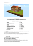
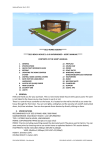
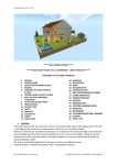
LLC «DISICON» Nizhniy Novgorod, urban type community Cherepichniy, 14 tel. / fax +7 (831) 411-55-97, lesdozor.ru support tel. 8 800 555 18 59 [email protected] USER MANUAL «Lesnoy Dozor» version 3.2 UPDATED 28.10.2015 Link to last update: http://www.lesdozor.com/presentations/usermanual.pdf 2 Content Ground based systems of forest protection using optical sensors and video cameras................................ 3 Important information! ...............................................................................................................................11 General information ....................................................................................................................................12 System consists of following elements: ..............................................................................................12 Server ..................................................................................................................................................12 Installation and basic setup.........................................................................................................................13 Installation...........................................................................................................................................13 Launching Application .........................................................................................................................15 Deleting application ............................................................................................................................16 User interface ..............................................................................................................................................17 Users ....................................................................................................................................................17 Objects and tabs ..................................................................................................................................17 Camera status icons ............................................................................................................................19 Main menu ..........................................................................................................................................20 Menu Map ...........................................................................................................................................23 Menu Map -> Layers............................................................................................................................24 Tool «Measure the distance»..............................................................................................................25 Status line ............................................................................................................................................26 Tools and contacts of tech support .....................................................................................................26 Checking the list of automatically found objects ........................................................................................27 Coordinates refinement “On videoclip”. .............................................................................................31 Coordinates refinement “In manual mode”. ......................................................................................33 How to see PDO marker on the map ..................................................................................................34 Real time mode camera control..................................................................................................................35 View routes window....................................................................................................................................44 Coordinates calculation with two cameras .................................................................................................47 Using fire watch tower azimuth for coordinates calculation ..............................................................49 Changing password .....................................................................................................................................50 Remote help via Team Viewer ....................................................................................................................51 Network speed test .....................................................................................................................................52 LAST UPDATE 28.10.2015 © LLC «DiSiCon», 2013 - 2015 3 Ground based systems of forest protection using optical sensors and video cameras 1. Forest monitoring methods: Satellite – large territories, very big delay in updating data. Aviation – large territories, very expensive, not regular. Ground based – Vehicle patrol and fire-watch towers. LAST UPDATE 28.10.2015 © LLC «DiSiCon», 2013 - 2015 4 2. Making a system of distributed video surveillance: - video cameras are installed on high rise objects; - all cameras are merged into a single network; - all cameras are connected to world wide web; - users connect to internet with a PC and work with numerous cameras; - several users can work with cameras being in different locations. The only thing needed is available internet connection. LAST UPDATE 28.10.2015 © LLC «DiSiCon», 2013 - 2015 5 3. Basic characteristic – detection range. Detection range depends on several factors. 3.1 The height of a tower, landscape profile. Chart 1. Dependency of straight visibility distance to height of a tower on a plain landscape. (height of average tree is 15 m) Tower height, m Distance of straight visibility, km Smoke height 20 m Smoke height 40 m 30 (standard fire watch tower) 60 70 90 110 (TV-Towers) 22 32 34 39 43 32 42 44 49 53 3.2 Atmosphere transparency. Chart 2. Distance of detection possibility in relation with different atmosphere transparency. Atmosphere transparency, km Detection range, km LAST UPDATE 28.10.2015 5 3,3 10 6,6 20 13,2 30 19,8 50 33 © LLC «DiSiCon», 2013 - 2015 100 66 6 3.3.Camera zoom. Chart 3. Maximum range of detection in dependence of camera zoom (standard camera with standard resolution): Zoom, x Detection range, km Size of smoke 10 м Size of smoke 50 м Size of smoke 100 м 1х 0,2 0,9 1,9 10х 1,9 9,3 18,7 20х 3,7 18,7 37,3 30х 5,6 28,0 56,0 35х макс 6,5 32,7 65,4 Chart 4. Maximum range of detection in dependence of camera zoom (standard camera with HD sensor): Detection range, km Zoom, x Size of smoke 10 м Size of smoke 50 м Size of smoke 100 м LAST UPDATE 28.10.2015 1х 0,5 2,6 5,3 5х 2,6 13,2 26,4 10х 5,3 26,4 52,9 20х макс 10,6 52,9 105,8 © LLC «DiSiCon», 2013 - 2015 7 4. Less personnel needed to control automated monitoring process. Chart 5. Detection time dependency with different amount of operating users and cameras in the system for “manual” and “automated” detection with detection range of 20 km and smoke size 50x50m. 1 operating user User+automation 2 operating users User+automation 5 operating users User+automation 10 operating users User+automation 20 operating users User+automation 1 cam. 30 min 30 min 30 min 30 min 30 min 30 min 30 min 30 min 30 min 30 min 3 cam. 1,5 hours 30 min 45 min 30 min 30 min 30 min 30 min 30 min 30 min 30 min 5 cam. 2,5 hours 30 min 1,2 hours 30 min 30 min 30 min 30 min 30 min 30 min 30 min 10 cam. 5 hours 30 min 2,5 hours 30 min 1 hour 30 min 30 min 30 min 30 min 30 min 20 cam. 10 hours 30 min 5 hours 30 min 2 hours 30 min 1 hour 30 min 30 min 30 min 50 cam. 25 hours 30 min 12,5 hours 30 min 5 hours 30 min 2,5 hours 30 min 1,25 hours 30 min 100 cam. 50 hours 1 hour 25 hours 30 min 10 hours 30 min 5 hours 30 min 2,5 hours 30 min Chart 5.1. Detection time dependency with different amount of operating users and cameras in the system for “manual” and “automated” detection with detection range of 10 km and smoke size 50x50m. 1 operating user User+automation 2 operating users User+automation 5 operating users User+automation 10 operating users User+automation 20 operating users User+automation 1 cam. 15 min 15 min 15 min 15 min 15 min 15 min 15 min 15 min 15 min 15 min LAST UPDATE 28.10.2015 3 cam. 45 min 15 min 22 min 15 min 15 min 15 min 15 min 15 min 15 min 15 min 5 cam. 1,25 hours 15 min 35 min 15 min 15 min 15 min 15 min 15 min 15 min 15 min 10 cam. 2,5 hours 15 min 1,2 hours 15 min 30 min 15 min 15 min 15 min 15 min 15 min 20 cam. 5 hours 15 min 2,5 hours 15 min 1 hour 15 min 30 min 15 min 15 min 15 min 50 cam. 12,5 hours 15 min 6,25 hours 15 min 2,5 hours 15 min 1,25 hours 15 min 35 min 15 min 100 cam. 25 hours 30 min 12,5 hours 15 min 5 hours 15 min 2,5 hours 15 min 1,25 hours 15 min © LLC «DiSiCon», 2013 - 2015 8 Chart 5.2. Detection time dependency with different amount of operating users and cameras in the system for “manual” and “automated” detection with detection range of 5 km and smoke size 50x50m. 1 operating user User+automation 2 operating users User+automation 5 operating users User+automation 10 operating users User+automation 20 operating users User+automation LAST UPDATE 28.10.2015 1 cam. 3 cam. 5 cam. 10 cam. 20 cam. 50 cam. 100 cam. 8 min 8 min 22 min 8 min 35 min 8 min 1,25 hours 8 min 2,5 hours 8 min 6,25 hours 8 min 12,5 hours 15 min 8 min 8 min 11 min 8 min 18 min 8 min 35 min 8 min 1,25 hours 8 min 3,12 hours 8 min 6,25 hours 8 min 8 min 8 min 8 min 8 min 8 min 8 min 15 min 8 min 30 min 8 min 1,25 hours 8 min 2,5 hours 8 min 8 min 8 min 8 min 8 min 8 min 8 min 8 min 8 min 15 min 8 min 35 min 8 min 1,25 hours 8 min 8 min 8 min 8 min 8 min 8 min 8 min 8 min 8 min 8 min 8 min 18 min 8 min 35 min 8 min © LLC «DiSiCon», 2013 - 2015 9 5. Costs and pricing. Chart 6. Basic components of the system and costs (month/year) if fire hazard season - 6 months. Components, system elements, labor Video surveillance equipment (+ additional) Installation and setting up Technical maintenance Coverage modelling for optimal towers positioning Software Towers rent Internet channels One-time costs 3800 € Recurring costs - 1500 € 40 – 100 €/240 – 600 € 80 – 160 €/360 – 960 € 10 – 60 €/70 – 360 € 20 – 240 €/120 – 1440 € - Chart 7. Internet channel pricing Internet channel speed, Mbit/s Cost per month , € Cost per fire hazard season, € LAST UPDATE 28.10.2015 0,5 20 120 1 40 240 2 60 360 4 120 720 © LLC «DiSiCon», 2013 - 2015 10 160 960 10 6. Coverage modelling. Preliminary modelling of system coverage will give larger territory under monitoring with fewer cameras. The quality of coverage depends on several factors: height of tower, landscape, atmosphere transparency, chosen hardware, etc. Without considering those factors might happen a situation, when the efficiency of real system is much lower than expected efficiency of project. Innovative modelling technologies can get a predictable result. The modelling can make emphasis on: forests in general, easy burning tree species, fires statistics for several years. All of that will help to reach the best economical effect on implementing the system. LAST UPDATE 28.10.2015 © LLC «DiSiCon», 2013 - 2015 11 Important information! Link to latest update of this user manual: lesdozor.ru/help Tech support phone number: 8 800 555 18 59 If during the operation is noticed that smoke was not being detected, please, inform tech support. Give camera`s name, azimuth and exact time of recording video clip. Send this data on email [email protected]. Lesnoy Dozor has integrated module of remote control “Team Viewer”. With its help you can temporary give access to tech support specialist for fixing desktop problems. Recommendations: Don`t capture cameras for a long time! Notice, in real time mode camera doesn`t follow the route and detection algorithm stop working, which can lead to fire source miss. Always install available update! Notice, that when detecting fire from single camera could be significant miss by distance. Use the Tool “Measure distance” to get more precise coordinates. Also keep in mind while using command “Mark smoke source” fire source is actually lower then visible smoke. If you cannot enter the system, first check if you have internet access (are you able to open web pages in browser?) LAST UPDATE 28.10.2015 © LLC «DiSiCon», 2013 - 2015 12 General information “Lesnoy Dozor” is a hardware-software information system for forest monitoring and detection of forest fires at an early stage. The system binds PTZ video cameras into network, connect them to powerful computers– servers, that connected to clients computers through world wide web. Clients` application “Lesnoy Dozor” – is special software. With its help you work with system, get fire coordinates, alarms, etc. System consists of following elements: 1. 2. 3. 4. 5. 6. Distributed network of cameras Internet channels System servers Server software “Lesnoy Dozor” Clients` computers Client`s application “Lesnoy Dozor”. Server System server functions: Storage and analysis of media data; Camera control; Smoke detection; Alarming on detection. LAST UPDATE 28.10.2015 © LLC «DiSiCon», 2013 - 2015 13 Installation and basic setup Installation Before installation of new version please delete the old one (if it was installed). Clients` application “Lesnoy Dozor” are compatible with operations systems Windows Vista, Windows 7, Windows 8. Windows XP and older operating systems are not supported. Open web browser to begin installation and go to: http://lesdozor.ru/a This page will show up: Press button «Install». Doubleclick downloaded file. Press “Run” in warning window. LAST UPDATE 28.10.2015 © LLC «DiSiCon», 2013 - 2015 14 Press “Install”. Then, you will see a progress bar. Installation should finish automatically. After that you should see this form: READ LICENSE AGREEMENT! If you agree, check “I agree”, then enter you login and password. To save your credentials check “Remember” box. To launch for the first time press “Ok”. LAST UPDATE 28.10.2015 © LLC «DiSiCon», 2013 - 2015 15 Launching Application 1. Double click the icon on a desktop to start application. Then, you will see this window. Application is trying to connect server. If there is updates, you will be offered to download them. Always accept updates! 2. Then, enter the system with your credentials as described above. 3. Press “ok”. LAST UPDATE 28.10.2015 © LLC «DiSiCon», 2013 - 2015 16 Deleting application To delete “Lesnoy Dozor” use standard Windows tools of Control Panel. Find the application in the list of installed programms and press Uninstall/Change. Choose «Remove the application from this computer»: Press “Ok”. Application has been deleted now. LAST UPDATE 28.10.2015 © LLC «DiSiCon», 2013 - 2015 17 User interface Users User interface configuration depends on user type. The user can be: Spectator – can observe monitoring routes. Validator – same as previous plus right to confirm or decline PDOs. Operator – same as previous plus right to control cameras in real time. Administrator – same as previous plus right to manage users of region and edit routes. This user manual describes functions, that are open to operators. Objects and tabs There are several types of objects: cameras fires users routes towers landmarks To work with object you need press one of those buttons: Different objects shown on the map: Potentially Dangerous Object Landmark Tower Camera Fire LAST UPDATE 28.10.2015 © LLC «DiSiCon», 2013 - 2015 18 In the upper right corner of navigation window located buttons: “flat list”, plus – “expand”, minus – «minimize»: Button “flat list”. LAST UPDATE 28.10.2015 © LLC «DiSiCon», 2013 - 2015 19 Camera status icons What mean different camera icons in tree of objects. Green – ok, camera recording the route. Red – could indicate that camera is busy with service procedure. But if this indicates for 10 minutes and more, this could be an error. Ask for assistance “Lesnoy Dozor” tech support. Icon and letters are grey – camera is off, probably no electricity or internet channel. Ask for assistance maintenance organization of your region or tower owner. Could be temporary service and camera will be available again. Icon without additional marks – camera is available and ready for work, but the routes are off or not created yet. Yellow icon – camera is captured in real time mode by user or service procedure utility. At this moment routes are off, algorithm doesn`t work. LAST UPDATE 28.10.2015 © LLC «DiSiCon», 2013 - 2015 20 Main menu In the upper left corner you can see four buttons: «File», «Map», «Tools» and «Help». Menu «File» contains buttons «Export», «Import», «External data», «Settings» и «Exit»: Option «Export» allows to extract data about fires, PDOs, routes in .csv format. Option «External data» allows to switch on functions like satellite fires data or cars` GPS coordinates, if you have this option in your region. LAST UPDATE 28.10.2015 © LLC «DiSiCon», 2013 - 2015 21 «Settings» window: «General». Here you can choose interface language, coordinates format and icon size. «Map». Choose a background map here. «Media». Choose type of image enhancer here. To let reduce costs on internet channels, the image processing was moved from camera into client`s application. It is recommended to use Enhanced sharpness. LAST UPDATE 28.10.2015 © LLC «DiSiCon», 2013 - 2015 22 “PDO” Turn on or off alarm signal on PDO detection. LAST UPDATE 28.10.2015 © LLC «DiSiCon», 2013 - 2015 23 Menu Map This menu helps mainly to switch on and off visibility of objects on the map. If you don`t see any objects that you need to see (confirmed/non confirmed PDOs, towers, cameras) go here in Map menu and turn them on. For cameras there are parameters: location real time mode sector coverage monitoring route sector PDO sector orientation point of view Just like that parameters for other objects turn on and off: Towers, Fires, PDOs and Landmarks. LAST UPDATE 28.10.2015 © LLC «DiSiCon», 2013 - 2015 24 Menu Map -> Layers Here you can switch on additional layers such as topography of forest map and others. In this menu you can turn on scale. LAST UPDATE 28.10.2015 © LLC «DiSiCon», 2013 - 2015 25 Tool «Measure the distance» This tool works like a ruler. You can measure the distance between camera and PDO for example. Also you get and angle. To reset for new measirement press To deactivate tool press LAST UPDATE 28.10.2015 . . © LLC «DiSiCon», 2013 - 2015 26 Status line In lower right corner the current number of unconfirmed/confirmed PDOs and fires in the system are displayed. As well as current time. If you hover mouse over those buttons (without clicking) you will see this: If you click the button with unconfirmed PDOs the “PDO analysis” window will appear. If you click the button with number of confirmed PDO and fires “Fire analysis” window will appear. Tools and contacts of tech support In upper right corner you can find contacts of technical support service: phone number (free for Russian phones), e-mail and skype. Also, here you can find the button “Remote help via TeamViewer” the calls the module of remote control. LAST UPDATE 28.10.2015 © LLC «DiSiCon», 2013 - 2015 27 Checking the list of automatically found objects Before starting the explanation of the window itself and the workflow, it is needed to understand, that: The cameras in the system move according to programmed monitoring routes. The cameras record point by point, forming video archive and panorama. Each movie clip is analyzed by detection algorithm. When there is no smoke and no potentially dangerous movements on video, the movie clip just goes to archive without warning the user. But is there is smoke, or something that looks like smoke, the movie clip goes into PDO analysis window followed by the warning sound (unless turned off) and you will see an increased number in a counter of status bar. And now it`s time to open PDO Analysis window (Analysis of potentially Dangerous Objects). Press Tools – PDO analysis: Or Counter button itself: LAST UPDATE 28.10.2015 © LLC «DiSiCon», 2013 - 2015 28 After that you will see this window: If you just have started work, on the left you will see the list of potentially dangerous objects, collected for last 2 hours. Objects that are older than 2 hours will be automatically deleted. On the right side you will see the movie clip of selected PDO, where smoke was detected. Smoke (or false alarms as well) is marked with red rectangles. Under the playback area there is a toolbar with buttons: Show in panorama (opens routes window with selected clip) Show preview only (for slow internet, shows images instead of video) Play selected clip Show objects on video (objects like PDOs, towers, landmarks, etc.) Show detected smoke sources (show or hide rectangles) Magnifier Underneath the tool bar there are information panels. LAST UPDATE 28.10.2015 © LLC «DiSiCon», 2013 - 2015 29 On the yellow background you can see information about movie clip: Camera Route Azimuth of frame`s center Time of detection On the right we can see an area with two tabs: Object and Camera. Object tab contains object coordinates and estimated Inaccuracy possibility. Camera tab contains camera coordinates and azimuth on object. And finally, in the PDO analisys window you can see three large buttons: With a help of them the user deletes PDO (by pressing No dangerous fumes) or confirmes PDO with recalculatating coordinates in one of two ways (In manual mode or right in the same window On videoclip). But before having a closer look at them, let`s see, how software calculates coordinates from single camera. LAST UPDATE 28.10.2015 © LLC «DiSiCon», 2013 - 2015 30 When smoke is detected, the system, knowing the height of camera, projects the point on the image into digital terrain map. But very often the visible smoke is much higher that actuall smoke source. (Tree height for example.) Or there could be a situation like that: As you can see, there is no intersection of projection with earth. And the marker goes on the edge of sector. This coordinates are obviously wrong, that is why the user should mark smoke source manually. And for that we have two buttons, as was told before: “In manual mode” and “On videoclip”. First, let`s have a look at defining smoke on videoclip, because it is easier and you don`t need to open other windows. LAST UPDATE 28.10.2015 © LLC «DiSiCon», 2013 - 2015 31 Coordinates refinement “On videoclip”. Imagine, you went through the list of PDOs and saw a movie clip with smoke. Then you pressed button Locate fire source: On videoclip. Right after that you will see in the center of the image a message: select the proposed area of PDO. Then, you hover your cursor over the image, press and hold left button of mouse. Then, you move cursor, that now looks likepointed down arrow, to the smoke source location. And only after that release the left mouse button. LAST UPDATE 28.10.2015 © LLC «DiSiCon», 2013 - 2015 32 Right after that the system will recalculate coordinates and open new PDO Property window: Press Save to confirm this PDO and send it to Fire Analysis window. Also you will see on the map the marker of confirmed PDO: This complicated at first sight procedure helps to avoid accidental misses. LAST UPDATE 28.10.2015 © LLC «DiSiCon», 2013 - 2015 33 Coordinates refinement “In manual mode”. Capture control on the camera by pressing the button “In manual mode”. Zoom as close as possible on the smoke and fire source. (The closer, the better precision of coordinates calculation). Then, in real time mode window find the button: Mark smoke source (the largest button). Then, as in previous method, you will see in the center of the image a message: select the proposed area of PDO: Everything else is as it was described above: Press mouse button, hold, locate source, release. After that you will get the same confirmed PDO property window with new, more precise coordinates. LAST UPDATE 28.10.2015 © LLC «DiSiCon», 2013 - 2015 34 How to see PDO marker on the map In upper left corner of the PDO analysis window there is a button “Show on the map”: When it is pressed, choosing a PDO in the list moves the map automatically to show this certain PDO in its center. All the other objects, except this PDO and camera, becomes almost transparent. This arrow represents cameras current position This arrow represents azimuth in the moment of movie clip recording All the other objects are faded LAST UPDATE 28.10.2015 © LLC «DiSiCon», 2013 - 2015 35 Real time mode camera control Real time mode should be used mainly for more accurate definition of fire source and also for more precise coordinate’s calculation. Real time mode SHOULDN`T be using constantly! It is obvious but important to understand that in real time mode camera stops analysing the rest of the route what can lead to fire miss. Also important to know that if one user has captured control, no one else can capture this camera. That is why the mode is DEFINING but not BASIC. You can capture camera control by several methods: 1. Pick one in the tree or on the map, right click it and choose “Capture control”: или 2. Press button capture control in “View routes” window: Notice, camera opens in same point of view as selected monitoring point. LAST UPDATE 28.10.2015 © LLC «DiSiCon», 2013 - 2015 36 3. From PDO analysis window: 4. From Fire analysis window: LAST UPDATE 28.10.2015 © LLC «DiSiCon», 2013 - 2015 37 Now have a look at real time window elements. Image quality selector Mark smoke source Measure distance Request indicator Show objects on video Show additional information Camera positioning by double click on map LAST UPDATE 28.10.2015 Magnifier Show camera in the center of map Show/hide control panel Joystick mode © LLC «DiSiCon», 2013 - 2015 38 1. «Quality». Here you can select image quality. Always use best unless you have slow internet. 2. «i» – information. Current size of window Quality Azimuth Zoom Min/max detection range. Initial: depends on resolution and zoom. Current: depends on window size. FPS Angles of view Information display Distance – is a characteristic the shows estimately the possibility of fire detection of certain size on certain amount of kilometers. Initial distance depends on zoom and sensor definition, current distance depends on physical size of the window. LAST UPDATE 28.10.2015 © LLC «DiSiCon», 2013 - 2015 39 3. «Show objects on video» Turns on objects` bubbles inside of the window as they are displayed on the map. Here is an example of tower object marker on video: LAST UPDATE 28.10.2015 © LLC «DiSiCon», 2013 - 2015 40 4. «Measure distance» You can calculate distance to certain object if you know or can estimate it`s size. The “measure distance” tool helps with that. Make an interval between start and end point and enter size in meters. After that you get distance to object. 5. «Follow double clicks on map» One of the ways to control camera is double clicking on the map in the point of interest. Press the button shown above to activate this function. 6. «Show in the center» Press this button to place camera marker in the center of the map. LAST UPDATE 28.10.2015 © LLC «DiSiCon», 2013 - 2015 41 7. «Joystick mode» In this mode camera is controlled by dragging the little arrow around center. Camera follows the arrow. 8. «Magnifier» Tool magnifies circlular region on the video with selectable strength. LAST UPDATE 28.10.2015 © LLC «DiSiCon», 2013 - 2015 42 9. «Show/hide control panel» You can expand the panel or hide faders by clicking little arrow in lower right corner. Shown faders control camera`s pan, tilt and zoom. LAST UPDATE 28.10.2015 © LLC «DiSiCon», 2013 - 2015 43 10. «Mark smoke source» This command is applicable when you see smoke on video and need to calculate coordinates and create confirmed PDO. Notice, that fire source is usually lower than visible smoke. Also, use high zoom for precision. After you marked the spot the properties window will appear. After pressing “Ok”, the PDO marker will appear on the map. Important! Coordinates, calculated for unconfirmed PDO has lower precision than has PDO created from real time mode. LAST UPDATE 28.10.2015 © LLC «DiSiCon», 2013 - 2015 44 View routes window View route window serves for visual monitoring of territory without capturing camera control, therefore without interrupting routes and automatic analysis. This window also shows have the route where configured, how ban zones where drawn and so on. To open this window, right click camera`s marker or camera`s name in tree of objects, then choose monitoring route. Or just double click on camera. The window will open: Those tree buttons open additional sections of the window, routes, panorama and timeline: On the bottom section you can see panorama with azimuth ruler, marked from 0 to 360 degrees. LAST UPDATE 28.10.2015 © LLC «DiSiCon», 2013 - 2015 45 On routes section on the left you will see created routes for chosen camera. Choose the route if you want to look at it separately from others. Now let`s have a closer look at panorama. You can see an array of recording points. These are last recorded movie clips. Click on any of them and the playback will start. If button “Play selected clip” pressed the playback will be starting immediately. Left button on the panel is “Play the route”. Press it if you want to watch all lately recorded clip one by one in cycle. You can play and stop video with these buttons: Selected camera will be highlighted on the map with red tracing , and violet sector will show up. It is oriented exactly like when camera was looking while recording this particular movie clip. So it is not camera`s actual position. LAST UPDATE 28.10.2015 © LLC «DiSiCon», 2013 - 2015 46 Sector of view for “far” route. Sector of view for “close” route. Notice, how the sector changes while draging window size. The bigger the image, the longer the sector. LAST UPDATE 28.10.2015 © LLC «DiSiCon», 2013 - 2015 47 Coordinates calculation with two cameras When smoke is detected, watch if you can see it from another camera. This will help to calculate coordinates more precisely. First, open camera, that detected the smoke. You can open from PDO analysis window by pressing “In manual mode” button. Then, position camera on the smoke and zoom as close as it is possible. LAST UPDATE 28.10.2015 © LLC «DiSiCon», 2013 - 2015 48 Do the same with second camera. Now, you can see smoke on two cameras. Now, look on the map. You should see a marker of intersection. Right click on it and choose new confirmed PDO of New Fire. After that the properties window of new PDO will appear with calculated coordinates. Press “Ok” to finish and send object into Fire Analysis window. LAST UPDATE 28.10.2015 © LLC «DiSiCon», 2013 - 2015 49 Using fire watch tower azimuth for coordinates calculation Instead of second camera you can use information from fire watch tower – azimuth on smoke. Object tower in “Lesnoy Dozor” has an azimuth arrow. Right click on tower marker on the map, choose “Set azimuth”. Then, enter a value or move fader. Notice, how the arrow moves. When this azimuth arrow cross camera`s direction line, you will see marker of intersection. Attention! If azimuth is defined with compass, enter data in «Magnetic azimuth» section. Right click on marker and choose “Create PDO” or “Create Fire”. LAST UPDATE 28.10.2015 © LLC «DiSiCon», 2013 - 2015 50 Changing password Every user can change and must change password from time to time. To do that, you need to press your system name in lower left corner of main window. Credentials window will appear. Enter old password. Enter new one. Repeat new in the next line. Press “Ok”. Notice! Password should contain capitals, figures and special signs. For example: forestR123#@ LAST UPDATE 28.10.2015 © LLC «DiSiCon», 2013 - 2015 51 Remote help via Team Viewer Software “Lesnoy Dozor” has integrated module of remote help Team Viewer. With its help you can give temporary access to support specialist to solve problems. You can run the module from authorization window with this button: , or by pressing the button in upper right corner of main window: After pressing on of those you will see TeamViewer window: Tell support specialist 9 numbers of your ID and wait for connection. Please, don`t use computer while support manager is connected unless you were asked. LAST UPDATE 28.10.2015 © LLC «DiSiCon», 2013 - 2015 52 Network speed test If the software works slowly or incorrectly, you can test your internet channel right from Lesnoy Dozor interface with build in utility. You can find it in Tools menu: Press “Start” to begin: After a little while you will get characteristics of key parameters: speed, stability, response time. Compare the results with this chart: Parameter Bad Download speed, less than 200 КB/s Packages lost more than 5 Ср. время отклика, ms more than 100 Ok 200 – 500 Perfect more than 500 1–5 0 40 – 100 less than 40 If one or several parameters are “Bad”, contact your internet provider support. LAST UPDATE 28.10.2015 © LLC «DiSiCon», 2013 - 2015


![Indicateurs (PDF/782Ko) [F]](http://vs1.manualzilla.com/store/data/006364555_1-61d6515c96ce437ed2545f3e53fb26c1-150x150.png)