1
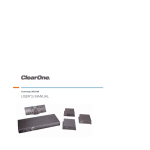
TABLETOP CONTROLLER
USER'S MANUAL
Preface
TABLETOP CONTROLLER USER’S MANUAL CLEARONE PART NO. 800-151-891 OCTOBER 2009 (REV. 2.1)
© 2009 ClearOne Communications, Inc. All rights reserved. No part of this document may be reproduced in any form or by any means
without written permission from ClearOne Communications. Printed in the United States of America. ClearOne reserves specific privileges.
Information in this document is subject to change without notice.
Telephone: 1-800-945-7730
Fax:
1-801-977-0087
Email:
[email protected]
Web Site:
www.clearone.com
Table of Contents
Chapter 1: Introduction
Product Overview
Service and Support
Technical Support
Product Returns
Important Safety Information
Unpacking
Chapter 2: Getting Started
Connecting Your Tabletop Controller
Using Controller Builder
Menus and Icons
Customizing Your Controller
Customizing the Dial Keys
Customizing the Room Audio Keys
Customizing the User Defined Keys
Controller Builder Status Bar
Common Commands
Chapter 3: Using the TableTop Controller
4
4
4
4
4
5
6
7
7
9
9
12
12
13
14
14
16
16
17
17
CHAPTER 1: INTRODUCTION
Product Overview
Thank you for purchasing the ClearOne Tabletop Controller for the Converge™ Pro professional conferencing
platform.
The Tabletop Controller is an intuitive, cost-effective controller that greatly simplifies control of an audio
conference without the need for expensive, intimidating touch panels. User-definable keys also offer simple
control of presentation, audio, and video conferencing functions.
Service and Support
If you need additional information on how to set up or operate your Tabletop Controller, please contact us. We
welcome and encourage your comments so we can continue to improve our products and better meet your
needs.
Technical Support
Telephone: 1.800.283.5936(USA) or 1.801.974.3760
Fax: 1.801.977.0087
E-mail: [email protected]
Web site: www.clearone.com
Product Returns
All product returns require a return materials authorization (RMA) number. Please contact ClearOne Technical
Support before attempting to return your product. Make sure you return all the items that shipped with your
product.
IMPORTANT SAFETY INFORMATION
Read the safety instructions before first use of this product. This conferencing phone is not designed for
making emergency telephone calls when the power fails. Make alternative arrangements for access to
emergency services.
1.
2.
3.
4.
5.
6.
7.
8.
9.
10.
11.
12.
13.
14.
15.
16.
17.
18.
19.
Read these instructions.
Keep these instructions.
Heed all warnings.
Follow all instructions.
Do not use this apparatus near water.
Clean only with dry cloth.
Do not block any ventilation openings. Install in accordance with the manufacturer’s instructions.
Do not install near any heat sources such as radiators, heat registers, stoves, or other apparatus (including amplifiers)
that produce heat.
Do not defeat the safety purpose of the polarized or grounding-type plug. A polarized plug has two blades with one
wider than the other. A grounding type plug has two blades and a third grounding prong. The wide blade or the third
prong are provided for your safety. If the provided plug does not fit into your outlet, consult an electrician for replacement of the obsolete outlet. Apparatet skal tilkoples jordet stikkontakt.
Protect the power cord from being walked on or pinched particularly at plugs, convenience receptacles, and the point
where they exit from the apparatus.
Only use attachments/accessories specified by the manufacturer.
Use only with the cart, stand, tripod, bracket, or table specified by the manufacturer, or sold with the apparatus. When a
cart is used, use caution when moving the cart/apparatus combination to avoid injury from tip-over.
Unplug this apparatus during lightning storms or when unused for long periods of time.
Refer all servicing to qualified service personnel. Servicing is required when the apparatus has been damaged in any
way, such as power-supply cord or plug is damaged, liquid has been spilled or objects have fallen into the apparatus,
the apparatus has been exposed to rain or moisture, does not operate normally, or has been dropped.
Use the mains plug to disconnect the apparatus from the AC mains. The mains plug shall remain readily operable.
To completely disconnect unit power from the AC mains, disconnect the unit’s power cord from the mains socket. To
reconnect power, plug the unit’s power cord into the mains socket following all safety instructions and guidelines.
Caution: Danger of explosion if lithium battery is incorrectly displaced. Replace only with the same or equivalent type. Battery should only be replaced by qualified personnel and is not intended as a user serviceable part. Do not expose batteries or battery pack to excessive heat such as prolonged sunlight, fire or other heat sources.
Never push objects of any kind into this product through cabinet slots as they may touch dangerous voltage points or
short out parts that could result in fire or electric shock.
This product can interfere with electrical equipment such as tape recorders, TV sets, radios, computers and microwave
ovens if placed in close proximity.
UNPACKING
Place the Tabletop Controller on a level surface. Ensure you have received all items shown in diagram below.
WARNING: You must use the power adapter provided: for use with Phihong Technology
Co. Ltd. Power Adapter Model No. PSA11R-120 or Globtek Power Adapter Model GT-415021512. Pour utiliser avec Phihong Technology Co. Ltd. Bloc d’Alimentation Modele PSA11R-120
or Globtek Bloc d’Alimentation Modele GT-41502-1512.
Note: ClearOne is not responsible for product damage incurred during shipment. You must
make claims directly with the carrier. Inspect your shipment carefully for obvious signs of
damage. If the shipment appears damaged, retain the original boxes and packing material for
inspection by the carrier. Contact your carrier immediately.
CHAPTER 2: GETTING STARTED
Connecting Your Tabletop Controller
1. Connect the Tabletop Controller to your PC . With the Tabletop Controller connected to your PC, you
can launch the Controller Builder application in order to customize the controller to your system.
WARNING: Do not connect the Tabletop Controller to a phone line as equipment failure or
damage may result.
2. After you have customized your Tabletop Controller according to your system’s specifics using the Controller Builder software (see Using Controller Builder for more information), you can then connect the
controller to your system.
WARNING: Do not connect the Tabletop Controller to a phone line as equipment failure or
damage may result.
USING CONTROLLER BUILDER
Launch Controller Builder by double-clicking the Controller Builder icon.
Controller Builder will launch with the Dial Keys button selected.
Menus and Icons
New: Creates a new Builder session
Open: Opens a previously created Builder session
Save/Save As: Saves the current Builder session
Connect: Connects to a device
Note: This menu item is available only when Controller Builder is not connected to the
Tabletop Controller.
Note: When the Tabletop Controller is connected to a Converge unit, not only must the baud
rate on the Converge be set to either 38,400 or 57,600, but flow control must also be set to
OFF--refer to your User’s Manual for instructions on how to set these parameters, if necessary.
Using the drop-down arrow, select your PC’s COM (serial) port to which you have connected the Tabletop
Controller and the baud rate for that port, then click Connect. A message window prompts you to save your
current settings. Click Yes to save the settings or No to continue the upload without saving. A progress bar in
the status bar tracks the progress of the connection and the light in the bottom right corner of the status bar
lights yellow while the status bar displays “Connecting...” When the connection is completed, the light turns
green and the status bar displays “Connected”. The Sync to Controller dialog appears.
The buttons in the Sync to Controller dialog function as follows:
l Upload from Controller - Uploads the controller settings to Controller Builder. The Tabletop Controller’s LCD screen displays “Uploading User Keys in Progress” and “Uploading User Keys Done”
when the upload is complete.
l Download to Controller - Downloads the current Controller Builder XCF file to the controller. The
Tabletop Controller’s LCD screen displays “Downloading User Keys in Progress” and “Downloading
User Keys Done” when the download is complete.
l Cancel - Cancels any changes made and closes the dialog.
Disconnect: Disconnects from a device
Note: This menu item is available only when Controller Builder is connected to the Tabletop
Controller.
Upload: Uploads a document from the controller to a connected device
Download: Downloads a document from a connected device to the controller
Help: Activates the Help file
Dial Keys Button: Selects the Dial Keys key grouping
Room Audio Keys: Selects the Room Audio Keys key grouping
User Defined Keys: Selects the User Defined Keys key grouping
CUSTOMIZING YOUR CONTROLLER
Understanding the functions of the key grouping buttons, description fields, command editor, and status
editor are best explained by describing the process for customizing the various keys for your controller.
Customizing the Dial Keys
Customizing the dial keys enables you to determine which telco device your controller will control for dialing
purposes. The following process describes how to customize the dial keys for your controller:
1. Click the Dial Keys button. The dial keys are outlined in the Controller Builder window.
2. In the Unit to dial with field in the Command Editor at the bottom of the Controller Builder window,
select the device type that will be performing the dialing and that device's ID (DID) (the asterisk “*” indicates all devices--or global) from the drop-down menus. The available devices are all telco devices.
Note: The name that appears on your Tabletop Controller’s display is the name of the unit you
choose to dial with in the Unit to dial with field. If you wish to change this name, refer to your
Converge Pro User’s Manual for the more information.
3. When you are finished, save your settings by clicking the Save icon
4. If Controller Builder is currently connected to the Tabletop Controller, continue with step 5. If not, connect to the controller (see the Connect menu for information on how to connect to the Tabletop Controller).
5. Click the Download Document to the Controller icon or the Apply button to transfer the settings to
the controller. The controller display shows the status of the settings being downloaded to the controller and when the transfer is completed.
Note: If you do not download the settings to the controller before closing Controller Builder,
then your Tabletop Controller WILL NOT be programmed with the new settings--changes made
in Controller Builder are not automatically downloaded to the controller.
Customizing the Room Audio Keys
Customizing the room audio keys enables you to indicate which devices you wish to control with the mute and
volume keys. The beauty of this customization is that you can set the controller to control specific groups of
inputs, outputs, microphones, or other groups associated with a given device (or devices) with these keys.
The following process describes how to customize the room audio keys for your Tabletop Controller:
1. Click the Room Audio Keys button. The MUTE, UP (volume up), and DOWN (volume down) keys
are outlined in the Controller Builder window. Click the key you wish to modify or select the key from the
Select Key drop-down list. The Command Description and Argument Description fields describe
the command you select and the argument (if any) for that command.
The fields in the Command Editor and Status Editor at the bottom of the Controller Builder
window change depending on which key you choose to customize. For example, if you are
customizing the MUTE key and choose the MUTE command, then you can only select the
device type, DID, command, channel, group, and value for the press and release states (see
Figure 2.8). If you are customizing the DOWN key and choose the RAMP command, then the
you can select the device type, DID, command, channel, group, rate, and target for the press
and release states. The Status Editor fields also change according to the key selected.
2. Click the key you wish to customize and select the command and parameters for that command that
you desire--you can choose from MACRO, MUTE, and NONE for the mute key or RAMP, GAIN,
MACRO, and NONE for the volume keys. All commands and parameters are standard Converge Pro
commands and parameters. If you need further clarification of any of these commands or parameters,
please refer to the specific Converge Pro User’s Manual for your system. Note that the command
NONE means that the key will be inactive and that nothing will happen when it is pressed or released.
Note: When you use the MACRO command, be sure that your macros are correct. Controller
Builder does not control macros, it simply programs your controller to run the macro when the
specific key is pressed or released and then display the results you desire in the controller’s
display window.
3. When you are finished, save your settings by clicking the Save icon.
4. If Controller Builder is currently connected to the Tabletop Controller, continue with step 5. If not, connect to the controller (see the Connect menu for information on how to connect to the Tabletop Controller).
5. Click the Download Document to the Controller icon or the Apply button to transfer the settings to
the controller. The controller display shows the status of the settings being downloaded to the controller and when the transfer is completed.
Note: If you do not download the settings to the controller before closing Controller Builder,
then your Tabletop Controller WILL NOT be programmed with the new settings--changes made
in Controller Builder are not automatically downloaded to the controller.
Customizing the User Defined Keys
Customizing the user defined keys enables you to use your Tabletop Controller to control a myriad of devices
and functions. These keys can be programmed with any of the following commands: GAIN, MACRO,
MCMACRO, MCMUTE, MCRAMP, MUTE, PRESET, RAMP, SPEEDDIAL, XSPEEDDIAL, STRING or
NONE. The following process describes how to customize the room audio keys for your Tabletop Controller:
1. Click the User Defined Keys button. The USER 1, USER 2, USER 3, USER 4, and USER 5 keys
are outlined in the Controller Builder window. Click the key you wish to modify or select the key from the
Select Key drop-down list.
2. The process for customizing the User Defined Keys is the same as has been discussed previously
in Customizing Dial Keys and Customizing Room Audio Keys. Follow those procedures in order to customize your User Defined Keys.
3. The Active Text and Inactive Text fields allow you to input the text (no more than 16 characters) you
wish to have displayed on your Tabletop Controller’s display window when the specific state occurs.
For example, if you have a Converge Pro 880 TA with program audio coming in on input 5, you might
want to configure the User 1key to toggle the mute status of input 5 so that whenever input 5 is muted,
the Active Text displays, “Program Muted” on the controller’s display and when input 5 is unmuted
the Inactive Text displays “Program Unmuted” on the controller’s display. After customizing the user
keys, enter whatever active or inactive text you wish to appear on the controller's display.
4. When you are finished, save your settings by clicking the Save icon
5. If Controller Builder is currently connected to the Tabletop Controller, continue with step 5. If not, connect to the controller (see the Connect menu for information on how to connect to the Tabletop Controller).
6. Click the Download Document to the Controller icon or the Apply button to transfer the settings to
the controller. The controller display shows the status of the settings being downloaded to the controller and when the transfer is completed.
Note: If you do not download the settings to the controller before closing Controller Builder,
then your Tabletop Controller WILL NOT be programmed with the new settings--changes made
in Controller Builder are not automatically downloaded to the controller.
Controller Builder Status Bar
The status bar displays the current status of Controller Builder, including the error status and connection
status with the Tabletop Controller.
When Controller Builder is connected to the Tabletop Controller, the status light at the far right of the status
bar illuminates green and the word "Connected" is displayed. When Controller Builder is in the process of
connecting to the controller, a progress bar in the status bar tracks the progress of the connection while the
status light is yellow and the word "Connecting..." is displayed. If Controller Builder is not connected to the
Tabletop Controller, then the status light is red and the words "Not Connected" are displayed.
The read (R) and write (W) status is also displayed and a progress bar appears tracking the upload and
download progress when those functions are performed.
Common Commands
Common commands used to program the Controller are listed in the table below.
Note: Not all commands are available to all units. Selecting a specific unit will reveal which
commands are available for that unit. This list covers all commands regardless of availability.
Command
Description
GAIN
This command changes or reports back the input gain for a channel.
MACRO
This command executes a specified macro or reports the last macro executed.
There are 255 macros that can be specified (Refer to your Converge Console manual for more information on macros).
MCGAIN
Controls the gain on a multi-channel group.
MCMUTE
Controls the mute on a multi-channel group.
MCRAMP
This command starts/stops the gain ramp for a multi-channel group. There is no
query for this command.
MUTE
This command selects/reports the setting of mute on input, output or processing
channels.
PRESET
This command selects/reports the state of a preset.
RAMP
This command starts/stops the gain ramp for an input, output, or assignable processing block. There is no query for this command.
SPEEDDIAL
Initiates the speed dial command in non-VoIP units.
XSPEEDDIAL
Initiates the speed dial command for VoIP units (VH20).
STRING
This command sends the specified string out the serial port.
CHAPTER 3: USING THE TABLETOP CONTROLLER
The table below describes the basic button functions of the tabletop controller.
Button
Function
Notes
Answer: Press to answer an incoming call
Dial: Press to initiate a call.
Pre-dial: Dial the phone number (using the * key to delete the last
digit). Press the Dialkey to send the call.
44 character maximum. Press and hold
(#) to insert a 2 second pause into the dialing string.
End: Press while on a call to disconnect.
Mute/Unmute: Press to mute the microphones. Press again to
unmute.
Redial: Redials the last outbound number dialed from the controller.
Flash: Press to transfer, use call waiting or conference calling.
Volume Up/Down: Use these buttons to increase or decrease
speaker volume.
This feature is dependent on your local PBX
feature set.