1
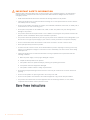
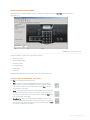
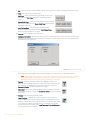
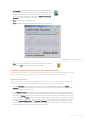
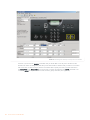
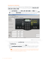
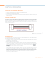
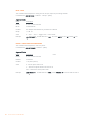
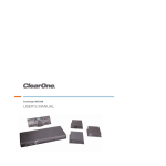
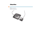
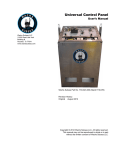
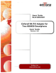
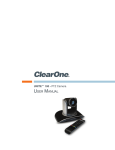
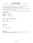
TABLETOP CONTROLLER
USER’S MANUAL
TABLE OF CONTENTS
TELEPHONE 1.800.283.5936
1.801.974.3760
FAX
EMAIL
1.801.977.0087
[email protected]
TABLETOP CONTROLLER USER’S MANUAL
CLEARONE PART NO. 800-151-891 FEBRUARY 2006 (REV. BETA)
© 2005 ClearOne Communications, iinc. All rights reserved. No
part of this document m ay be reproduced in any form or by any
means without written permission from ClearOne Communications.
Printed in the United States of America. ClearOne reserves specific
privileges. Inforfrmation in this document is subject to change without notice
TABLE OF CONTENTS CONTINUED
CHAPTER 1: INTRODUCTION
Product Overview . . . . . . . . . . . . . . . . . . . . . . . . . . . . . . . 1
Service and Support . . . . . . . . . . . . . . . . . . . . . . . . . . . . 1
Unpacking . . . . . . . . . . . . . . . . . . . . . . . . . . . . . . . . . . . . 3
CHAPTER 2: GETTING STARTED
Connecting Your Tabletop Controller . . . . . . . . . . . . . . . . 5
Installing Controller Builder Software. . . . . . . . . . . . . . . . 6
Using Controller Builder. . . . . . . . . . . . . . . . . . . . . . . . . . 7
Controller Builder Menus and Icons. . . . . . . . . . . . . . . 7
Customizing Your Tabletop Controller With
Controller Builder . . . . . . . . . . . . . . . . . . . . . . . . . . . . . . . 9
Customizing the Dial Keys . . . . . . . . . . . . . . . . . . . . . . 9
Customizing the Room Audio Keys . . . . . . . . . . . . . . 10
Customizing the User Defined Keys . . . . . . . . . . . . . 14
CHAPTER 3: USING THE TABLETOP CONTROLLER
To Answer a Call . . . . . . . . . . . . . . . . . . . . . . . . . . . . . . 15
To Make a Call . . . . . . . . . . . . . . . . . . . . . . . . . . . . . . . . 15
To Pre-Dial a Call . . . . . . . . . . . . . . . . . . . . . . . . . . . . . . 15
To End a Call . . . . . . . . . . . . . . . . . . . . . . . . . . . . . . . . . 15
To Mute/Unmute Microphones . . . . . . . . . . . . . . . . . . . 15
To Use Speed Dial . . . . . . . . . . . . . . . . . . . . . . . . . . . . . 15
To Redial a Phone Number . . . . . . . . . . . . . . . . . . . . . . 16
To Send a Flash Signal . . . . . . . . . . . . . . . . . . . . . . . . . 16
To Adjust Speaker Volume . . . . . . . . . . . . . . . . . . . . . . . 16
CHAPTER 4: MAINTENANCE
Caring for Your Tabletop Controller . . . . . . . . . . . . . . . . 17
Troubleshooting . . . . . . . . . . . . . . . . . . . . . . . . . . . . . . . 17
CHAPTER 5: APPENDIX
Specifications. . . . . . . . . . . . . . . . . . . . . . . . . . . . . . . . . 19
Serial Commands . . . . . . . . . . . . . . . . . . . . . . . . . . . . . 20
Compliance . . . . . . . . . . . . . . . . . . . . . . . . . . . . . . . . . . 27
Warranty . . . . . . . . . . . . . . . . . . . . . . . . . . . . . . . . . . . . . 28
CHAPTER 1: INTRODUCTION
PRODUCT OVERVIEW
Thank you for purchasing the ClearOne Tabletop Controller for the XAP professional
conferencing platform.
The Tabletop Controller is an intuitive, cost-effective controller that greatly simplifies control of an audio conference
without the need for expensive, intimidating touch panels. User-definable keys also offer simple control of
presentation, audio, and video conferencing functions.
SERVICE AND SUPPORT
If you need additional information on how to set up or operate your Tabletop Controller, please contact us. We
welcome and encourage your comments so we can continue to improve our products and better meet your
needs.
TECHNICAL SUPPORT
Telephone: 1.800.283.5936(USA) or 1.801.974.3760
Fax: 1.801.977.0087
E-mail: [email protected]
Web site: www.clearone.com
SALES AND CUSTOMER SERVICE
Telephone: 1.800.945.7730 (USA) or 1.801.975.7200
Fax: 1.800.933.5107 (USA) or 1.801.977.0087
E-mail: [email protected]
PRODUCT RETURNS
All product returns require a return materials authorization (RMA) number. Please contact ClearOne Technical
Support before attempting to return your product. Make sure you return all the items that shipped with your
product.
Chapter 1: Introduction
1
IMPORTANT SAFETY INFORMATION
Read the safety instructions before first use of this product. This conferencing phone is not designed for
making emergency telephone calls when the power fails. Make alternative arrangements for access to
emergency services.
•
Read and understand all instructions and follow all warnings marked on the product.
•
Unplug this product from the wall outlet before cleaning. Do not use liquid cleaners or aerosol cleaners.
Use a damp cloth for cleaning.
•
Do not use this product near water, for example, near a bathtub, washbowl, kitchen sink, or laundry tub, in
a wet basement, or near a swimming pool.
•
Do not place this product on an unstable cart, stand, or table. The product may fall, causing serious
damage to the product.
•
This product should never be placed near or over a radiator or heat register. This product should not be
placed in a built-in installation unless proper ventilation is provided.
•
This product should be operated only from the type of power source indicated on the marking label. If you
are not sure of the type of power supply in your location, consult your dealer or local power company.
•
Do not overload wall outlets and extension cords as this can result in fire risk or electric shock.
•
Never spill liquid of any kind on the product.
•
To reduce the risk of electric shock, do not disassemble this product. Opening or removing covers may
expose you to dangerous voltages or other risks. Incorrect reassembly can cause electric shock during
subsequent use.
•
Unplug this product from the wall outlet and refer servicing to qualified service personnel under the
following conditions:
a. When the power supply cord or plug is damaged or frayed.
b. If liquid has been spilled into the product.
c. If the product does not operate normally by following the operating instructions.
d. If the product has been dropped or damaged.
e. If the product exhibits a distinct change in performance.
•
Avoid using a telephone during an electrical storm. There may be a remote risk of electric shock from
lightning.
•
Do not use this product to report a gas leak in the vicinity of the leak.
•
Do not use this product near intensive care medical equipment or by persons with pacemakers.
•
This product can interfere with electrical equipment such as answering machines, TV sets, radios,
computers and microwave ovens if placed too close.
Save these instructions
2
Technical Services: 800.283.5936
UNPACKING
Carefully place the Tabletop Controller on a level surface. Ensure you have received all items shown in figure 1.
Tabletop Controller w/6’ cable
40’ cable
Y-Adapter
Documentation on CD
Female/Female
Null Modem
DB-9 Adapter
Stick-on Labels
for User-de ned Keys
Power Supply
FIGURE 1.1 Tabletop Controller parts
WARNING: You must use the power adapter provided: for use with Phihong Technology Co. Ltd. Power
Adapter Model No. PSA11R-120 or Globtek Power Adater Model GT-41502-1512. Pour utiliser avec
Phihong Technology Co. Ltd. Bloc d’Alimentation Modele PSA11R-120 or Globtek Bloc d’Alimentation
Modele GT-41502-1512.
>
Note: ClearOne is not responsible for product damage incurred during shipment. You must make claims
directly with the carrier. Inspect your shipment carefully for obvious signs of damage. If the shipment
appears damaged, retain the original boxes and packing material for inspection by the carrier. Contact
your carrier immediately.
Chapter 1: Introduction
3
4
Technical Services: 800.283.5936
CHAPTER 2: GETTING STARTED
CONNECTING YOUR TABLETOP CONTROLLER
1. Connect the Tabletop Controller to your PC as shown in Figure 2.1. With the Tabeltop Controller connected
to your PC, you can launch the Controller Builder application in order to customize the controller to your
XAP system.
PC
81.7/'
FIGURE 2.1 Connecting the Tabletop Controller to a PC
2. After you have customized your Tabletop Controller according to your system’s specifics using the
Controller Builder software (see Using Controller Builder on page 7 for more information), you can then
connect the controller to your XAP system as shown in Figure 2.2.
Chapter 2: Getting Started
5
81.7/'
FIGURE 2.2 Connecting the Tabletop Controller to a XAP
INSTALLING CONTROLLER BUILDER SOFTWARE
Controller Builder is the software you use to customize your Tabletop Controller to your XAP system. Perform
the following steps to install the software on your PC:
1. Insert the installation CD into your PC’s CD drive.
2. The installation wizard auto starts.
3. Follow the wizard’s prompts until the software is successfully installed.
4. Click Start -> Programs -> ClearOne Communications -> Controller Builder -> Controller Builder to start
the program.
6
Technical Services: 800.283.5936
USING CONTROLLER BUILDER
Upon starting the Controller Builder software, the main screen appears, with the Dial Keys button depressed
(see Figure 2.3).
FIGURE 2.3 Controller Builder main screen
Controller Builder is composed of the following sections:
•
Menus and icons
•
Key grouping buttons
•
Description fields
•
Command editor
•
Status editor
•
Status bar
The following paragraphs describe each of these sections and their use.
CONTROLLER BUILDER MENUS AND ICONS
The File menu contains the following items:
•
New - creates a new Controller Builder session. You are given the
option to save the current settings before a new session is created.
You can also activate this menu item by clicking the New icon (see
the illustration to the right).
•
Open - opens a previously saved Controller Builder session. A browse
window is opened for you to browse to the directory where the file is
saved. You can also activate this menu item by clicking the Open icon
(see the illustration to the right).
•
Save/Save As - saves the current Controller Builder session. A save
window is opened for you to browse to the directory where you wish to
save the file. You can also activate this menu item by clicking the Save
icon (see the illustration to the right).
Chapter 2: Getting Started
7
•
Exit - exits the current Controller Builder session. You are given the option of saving the file before exiting.
The View menu contains the following items:
•
Dial Keys - selects the dial keys key grouping, just as if you
had clicked the Dial Keys button (see the illustration to the
right).
•
Room Audio Keys - selects the room audio keys key grouping,
just as if you had clicked the Room Audio Keys button (see the
illustration to the right).
•
User Defined Keys - selects the user defined keys key
grouping, just as if you had clicked the User Defined Keys
button (see the illustration to the right).
The Connect menu contains the following items:
•
Configure Connection - allows you to select your PC’s COM (serial) port to which you have connected the
Tabletop Controller and identify the baud rate for that port. Click the radio buttons to set the specified port
and baud rate (see Figure 2.4).
FIGURE 2.4 Configure Connection dialog
This menu item is only available when Controller Builder is not connected to the Tabletop Controller.
>
Note: When the Tabletop Controller is connected to a XAP, not only must the baud rate on the XAP be
set to either 38,400 or 57,600, but flow control must also be set to OFF--refer to your XAP User’s
Manual for instructions on how to set these parameters, if necessary.
•
Connect - connects Controller Builder to the Tabletop Controller. The
Tabletop Controller window displays “Connected” and the baud rate once
the connection is established. You can also connect by clicking the
Connect to Device icon (see illustration to the right).
•
Disconnect - disconnects Controller Builder from the Tabletop Controller.
You can also do this by clicking the Connect to Device icon (see illustration
to the right).
The Transfer menu contains the following items:
•
8
From Controller - transfers the current settings from the controller to
Controller Builder. The controller display shows “Uploading user keys in
progress” followed by “Done” when the transfer is completed. This allows
you to verify the settings and modify them, if so desired. You can also
activate this function by clicking the Load Document From the Controller
icon (see illustration to the right).
Technical Services: 800.283.5936
•
To Controller - transfers the current settings from Controller Builder to
the controller. The controller display shows “Downloading user keys in
progress” followed by “Done” when the transfer is completed. You
can also activate this function by clicking the Upload Document to
Controller icon (see illustration to the right).
The Help menu contains the following items:
•
About - displays the About Controller Builder dialog (see Figure 2.5).
FIGURE 2.5 About Controller Builder dialog
•
Help - activates the help file. You can also activate this menu item by
clicking the Help icon (see the illustration to the right).
CUSTOMIZING YOUR TABLETOP CONTROLLER WITH CONTROLLER BUILDER
Understanding the functions of the key grouping buttons, description fields, command editor, and status editor
are best explained by describing the process for customizing the various keys for your controller.
Customizing the Dial Keys
Customizing the dial keys enables you to determine which telco device your controller will control for dialing
purposes. The following process describes how to customize the dial keys for your controller:
1. Click the Dial Keys button. The dial keys are outlined in the Controller Builder window. The Current
Selection description field instructs you to select the device type and device ID (DID) for the unit that will
perform the dialing (see Figure 2.6).
2. In the Command Editor at the bottom of the Controller Builder window, select the device type that will be
performing the dialing and the DID of that device from the drop-down menus. The available devices are all
telco devices; Current indicates that the device that the controller is currently connected to is the one that
will be controlled and Global means that all telco devices will be controlled--which, in this case, is probably
not a good idea...you would not want to have all your telco devices dialing the same number at the same
time! The Command Description and Argument Description fields describe the command you select (in
this case, a macro that tells the controller which telco device(s) it will be controlling for dialing functions)
and the argument (if any) for that command (see Figure 2.6).
Chapter 2: Getting Started
9
FIGURE 2.6 Customizing dial keys
3. When you are finished, save your settings by clicking the Save icon.
4. Click the Upload Document to the Controller icon to transfer the settings to the controller. The controller
display shows the status of the settings being downloaded to the controller and when the transfer is
completed.
>
Note: If you do not upload the settings to the controller before closing Controller Builder, then your
Tabletop Controller WILL NOT be programmed with the new settings--changes made in Controller
Builder are not automatically uploaded to the controller.
Customizing the Room Audio Keys
Customizing the room audio keys enables you to indicate which devices you wish to control with the mute and
volume keys. The beauty of this customization is that you can set the controller to control specific groups of
inputs, outputs, microphones, or other groups associated with a given device (or devices) with these keys. The
following process describes how to customize the room audio keys for your Tabletop Controller:
1. Click the Room Audio Keys button. The MUTE, UP (volume up), and DOWN (volume down) keys are
outlined in the Controller Builder window. Click the key you wish to modify or select the key from the Select
Key drop-down list. The Current Selection description field instructs you to select the device type and
device ID (DID) for the unit that will be affected when you press the selected key (see Figure 2.7).
10
Technical Services: 800.283.5936
FIGURE 2.7 Customizing room audio keys
Depending on which key you choose to customize, some fields in the Command Editor and Status Editor
at the bottom of the Controller Builder window will be editable and some will not. For example, if you are
customizing the MUTE key and choose the MUTE command, then you will only be able to select the
device, DID, channel, group, and value for the command, but the results that occur when you press or
release the key are defined by default and not editable, as shown by the grayed out fields in the Status
Editor (see Figure 2.8).
Chapter 2: Getting Started
11
FIGURE 2.8 Customizing room audio keys: mute key with mute command
However, if you choose the MACRO command, then you will be able to not only select the device, DID,
and ID of the macro as assigned by XAP, but you will also be able to indicate what you want to occur when
that macro runs, or when the key is pressed. You will be able to specify the result you want as shown in
the Active State in the Status Editor--you can choose to monitor the response of a MUTE command or no
command (NONE) for a particular device, DID, channel, group, and value (see Figure 2.9).
12
Technical Services: 800.283.5936
FIGURE 2.9 Customizing room audio keys:mute key with macro command
The important thing to remember is that the Press fields in the Command Editor are directly associated
with the Active State fields in the Status Editor and the Release fields in the Command Editor are directly
associated with the Inactive State fields in the Status Editor.
2. Click the key you wish to customize and select the command and parameters for that command that you
desire--you can choose from MACRO, MUTE, and NONE for the mute key or RAMP, GAIN, MACRO, and
NONE for the volume keys. All commands and parameters are standard XAP commands and parameters.
If you need further clarification of any of these commands or parameters, please refer to the specific XAP
User’s Manual for your system. Note that the command NONE means that the key will be inactive and that
nothing will happen when it is pressed or released.
>
Note: When you use the MACRO command, be sure that your macros are correct. Controller Builder
does not control macros, it simply programs your controller to run the macro when the specific key is
pressed or released and then display the results you desire in the controller’s display window.
3. The Active Text and Inactive Text fields, when editable, allow you to input the text (no more than 16
characters) you wish to have displayed on your Tabletop Controller’s display window when the specific
state occurs. For example, you might have a macro command running on the XAP 400 that will activate all
microphones on channel 1 on that device. When this occurs, you want all microphones on the XAP 800,
channel 4 to be disabled and the text, “Microphones disabled” to be displayed on the Tabletop
Controller’s display window when the macro runs. Input whatever text you want displayed into these fields.
4. When you are finished, save your settings by clicking the Save icon.
5. Click the Upload Document to the Controller icon to transfer the settings to the controller. The controller
display shows the status of the settings being downloaded to the controller and when the transfer is
completed.
>
Note: If you do not upload the settings to the controller before closing Controller Builder, then your
Tabletop Controller WILL NOT be programmed with the new settings--changes made in Controller
Builder are not automatically uploaded to the controller.
Chapter 2: Getting Started
13
Customizing the User Defined Keys
Customizing the user defined keys enables you to use your Tabletop Controller to control a myriad of devices
and functions. These keys can be programmed with any of the following commands: GAIN, MACRO, MUTE,
PRESET, RAMP, SPEEDDIAL, STRING, or NONE. The following process describes how to customize the room
audio keys for your Tabletop Controller:
1. Click the User Defined Keys button. The USER 1, USER 2, USER 3, USER 4, and USER 5 keys are
outlined in the Controller Builder window. Click the key you wish to modify or select the key from the Select
Key drop-down list. The Current Selection description field instructs you to select the device type and
device ID (DID) for the unit that will be affected when you press the selected key (see Figure 2.10).
FIGURE 2.10 Customizing user defined keys
2. The process for customizing the User Defined Keys is the same as has been discussed previously in
Customizing Dial Keys and Customizing Room Audio Keys. Follow those procedures in order to customize
your User Defined Keys.
3. When you are finished, save your settings by clicking the Save icon.
4. Click the Upload Document to the Controller icon to transfer the settings to the controller. The controller
display shows the status of the settings being downloaded to the controller and when the transfer is
completed.
>
14
Note: If you do not upload the settings to the controller before closing Controller Builder, then your
Tabletop Controller WILL NOT be programmed with the new settings--changes made in Controller
Builder are not automatically uploaded to the controller.
Technical Services: 800.283.5936
CHAPTER 3: USING THE TABLETOP CONTROLLER
TO ANSWER A CALL
1. Press
on the controller to answer the call. When there is an incoming call, you will see “ringing” on the.
controller display and the phone icon flashes.
TO MAKE A CALL
1. Press
. You will hear a dial tone.
2. Dial the number as you would on a standard phone. The number appears on the LCD screen.
> Note: The controller accepts a maximum of 44 pre-dialed characters. No more than 44 characters can be
entered.
TO PRE-DIAL A CALL
1. Dial a phone number. You can press the asterisk
pre-dialing string.
2. Press
*
(CLEAR) to delete the last digit entered in the
to send the call.
> Note: Pressing and holding the asterisk (*) key for two seconds will delete the entire dial string. Pressing
and holding the pound (#) key for two seconds will insert a pause into the dialing string. The duration of
the pause is two seconds.
TO END A CALL
1. Press
to disconnect the call.
TO MUTE/UNMUTE MICROPHONES
1. Press
to mute the microphones.
2. Press
again to unmute the microphones.
TO REDIAL A PHONE NUMBER
1. Press
.
> Note: REDIAL saves the last number that was dialed from the controller. Once REDIAL is pressed, the
phone will be taken off-hook and the number will be dialed.
Chapter 3: Using the Tabletop Controller
15
TO SEND A FLASH SIGNAL
1. Press
to use call transfer, call waiting, or conference calling.
> Note: This feature is dependent on your PBX service or local phone service. Refer to your PBX vendor or
local telephone service for details.
TO ADJUST THE SPEAKER VOLUME
16
1. Press
to increase the volume.
2. Press
to decrease the volume.
Technical Services: 800.283.5936
CHAPTER 4: MAINTENANCE
CARING FOR YOUR TABLETOP CONTROLLER
•
Follow all warnings and instructions marked on your Tabletop Controller.
•
Unplug from the wall outlet before cleaning.
•
Do not use liquid or aerosol cleaners. Use a damp cloth moistened with water to clean the outside of your
Tabletop Controller.
CREATING A CUSTOM CABLE
If you wish to extend the cable length from the Tabletop Controller to the XAP to the full 150’-certified length,
you will need to create a custom cable of this length using CAT-3 or better cable. You CANNOT use a standard
telephone cable because the pinouts in a standard telephone cable connector are not compatible with the Yadapter supplied with your Tabletop Controller. In creating a custom cable, be sure that the connector pinouts
match those shown in Figure 4.1.
FIGURE 4.1 Custom cable wiring diagram
TROUBLESHOOTING
If you are having trouble with your Tabletop Controller, it might be improperly set up or other equipment might
be malfunctioning. To begin, check for the following:
•
The Tabletop Controller is plugged into the proper electrical outlet and the LCD display shows “ClearOne,”
indicating that the unit is powered on.
•
Make sure cables are securely connected.
•
If error messages appear when the Tabletop Controller is connected to Controller Buider stating that the
controller is not connected or is searching, check that the correct port and baud rate are set for the serial
port that the Tabletop Controller is connected to on your PC. You can check this through the Configure
Connection dialog (see Configure Connection on page 8).
If error messages appear when the Tabletop Controller is connected to a XAP stating that the controller is
not connected or is searching, then verify that the correct baud rate is being used on the XAP. The only
baud rates permitted by the Tabletop Controller are 38,400 and 57,600. Upon connecting with the XAP, the
Tabletop Controller automatically matches one of these baud rates with the baud rate received from the
XAP. Flow control must also be set to OFF. Make these adjustments, if necessary, by following the
instructions in your XAP User’s Manual.
Chapter 4: Maintenance
17
18
Technical Services: 800.283.5936
CHAPTER 5: APPENDIX
SPECIFICATIONS
DIMENSIONS (W x D x H)
10.5” x 4.5” 2.75”
WEIGHT
2.0 lbs.
ENVIRONMENTAL
Operating Temperature: -32 to 122° F)
Operating Humidity: 15 to 80%
POWER SUPPLY
Input: 100 to 240 VAC, 50-60 Hz, 0.5 A
Output: 12 VDC, 0.83 A
RS-232 CONTROL PORT
DB9 Female
38,400/57,600 baud rate: 8 bits, 1 stop,
no parity
Flow Control: None
MAXIMUM DISTANCE FROM CONTROLLER
TO MIXER
150’ CAT 3 Cable
MODELS
910-151-890 Tabletop Controller
Chapter 5: Appendix
19
SERIAL COMMANDS
The XAP accepts serial commands through the serial port or the expansion bus. RS-232 serial port protocol is
38,400 or 57,600 baud; 8 bits, 1 stop bit, no parity.
CONVENTIONS
The following typographic conventions are used in this document to describe the different serial commands.
Use the Command structure section and the examples as a guide when creating your serial commands.
Convention
<X>
[X]
1-8
4,7,9
EREF
DEVICE
Description
Parameters enclosed in < > indicate a mandatory parameter.
Parameters enclosed in [ ] indicate an optional parameter.
Parameters separated by a hyphen (-) indicate a range between the
values.
Parameters separated by a comma (,) indicate a list of available
values.
Words in uppercase bold indicate command text.
Indicates the device type and device number on the expansion bus network.
COMMAND STRUCTURE
The following typographic conventions are used in this document to describe the different serial commands.
Use the Command structure section and the examples as a guide when creating your serial commands.
Commands can be either UPPERCASE or lowercase. Also, extra spaces or tabs between arguments in text
commands are allowed. Return values are always uppercase. In order for a command to be recognized by the
serial port, the command must be terminated by a carriage return.
The structure of serial commands is as follows:
#TYPE DEVICE COMMAND [X] [X]
#
indicates the start of a command line
DEVICE
represents the device type and device number
COMMAND
is the command text
[X] [X]
represents any additional options in the order that they appear in the command descriptions
that follow
Example:
A command to disable automatic gain control for Mic 2 on a XAP 800 device “0” will have the command line:
#50 AGC 2 M 0. In this command line, 5=XAP 800, 0=unit 0, AGC=command, 2=channel, M=Mic Input
group, 0=off state. If a command calls for a “null” value, leave a blank in the command line. For example,
“#50 AGC 2 M” will return the current AGC state of Mic 2 on device 50.
Command responses will have a carriage return line feed. For example, #50 AGC 2 M O carriage return line
feed.
GROUPS AND CHANNELS
If a channel has an alpha value of “*”, the command is to be applied to all channels. For example, a group
value of M and a channel value of “*” means that the command is to be applied to all channels of group M
(mic inputs). Table 5.1 shows the alpha representations for the different groups and the channels that are
available for each product.
20
Technical Services: 800.283.5936
FIGURE 5.1 Groups and channels
TYPE AND DEVICE IDS
Type ID
Unit type
Device ID range
5
6
7
XAP 800
XAP TH2
XAP 400
0-7
0-F
0-7
Chapter 5: Appendix
21
METER TYPE DEFINITIONS
FIGURE 5.2 Meter type definitions
SERIAL COMMAND ERROR CODES
22
Error number
Text message
Explanation/Solution
1
Memory error
The box is out of internal memory. Power cycle the box.
2
No command found
A command was not found in the string.
3
Unknown command
A command was executed on a different device type that this
box cannot display. The command dictionary needs to be
updated.
4
Not implemented
The command is not implemented.
5
Argument error
The command had an argument that was out of range.
6
Unknown command
The command is unknown to this unit.
7
Bad checksum
The binary command’s checksum is wrong.
8
Preset of macro invalid
A preset or macro failed to program because it is too large or
because its command list contained an invalid command.
10
Queue error
The internal command queue is full. Enable flow control and use
all five pins on the serial port.
11
Command too big
The binary command is too large.
12
Unit is locked
Unlock the unit with the proper password.
Technical Services: 800.283.5936
XAP SERIAL COMMANDS
Command
Function
GAIN
MACRO
MUTE
PRESET
RAMP
SPEEDDIAL
STRING
Changes/reports gain for in, out, or process
Executes macro or reports last macro executed
Sets/reports mute status
Executes preset or reports last executed preset
Starts/stops the gain ramp for an input, output, or assignable processing block
Dials one of ten numbers on the telco channel
Executes a string for the RS-232 port
GAIN - GAIN ADJUSTMENT
This command changes or reports back the input gain for a channel.
Command form: DEVICE GAIN <Channel> <Group> [Value A/R]
Argument Details
Name
Description
Device
0–7 or * to select all units
GAIN
Command form
Channel
See Groups and Channels, page 97
Group
I = Inputs, O = Outputs, M = Mic Inputs,
P = Processing Channels, L = Line Inputs
Value
-99 to 99 *, Null to return the current gain
A/R
A = Absolute, R = Relative, Null = Relative
Example:
#51 GAIN 4 O 12 A On XAP 800 unit 1 (#51), the GAIN for Output (O) 4 is set to 12dB
absolute (A).
>
Note: Values indicate entry range only. Actual internal range of the gain stage is from -65 to 20. Absolute
values will be limited to the internal gain range and values below -65 will mute the channel.
MACRO - MACRO EXECUTION/REPORTING
This command executes a specified macro or reports the last macro executed. There are 255 macros that can
be specified.
Command form: DEVICE MACRO [Value]
Argument Details
Name
Description
Device
0–7 or * to select all units
MACRO
Command form
Value
1-255
Example:
#55 MACRO 1 On XAP 800 unit 5 (#55), Macro (MACRO) 1 is run.
>
Value to execute user macros
Note: The response indicates execution of the macro, but does not indicate that each command within
the macro was executed.
Chapter 5: Appendix
23
MUTE - MUTE
This command selects/reports the setting of mute on input, output or processing channels.
Command form: DEVICE MUTE <Channel> <Group> [Value]
Argument details
Name
Description
Device
0–7 or * to select all units
MUTE
Command form
Channel
See Groups and Channels in your XAP User’s Manual
Group
I, O, M, P, L
Value
0 = Off, 1 = On, 2 = Toggle, Null = current mode
Example:
#51 MUTE 2 M 1 On XAP 800 unit 1 (#51), the mute (MUTE) for mic (M) channel 2 is on
(1).
PRESET - PRESET EXECUTION/REPORTING
This command selects/reports the state of a preset.
Command form: DEVICE PRESET <Channel> [Value]
Argument Details
24
Name
Description
Device
0–7 or * to select all units
PRESET
Command
Channel
1–32 (select preset)
Value
0 =Set the preset state to off
1 = Execute the preset and set the state to on
2 = Execute the preset and set the state to off
Null = Returns the current preset state
Example:
#52 PRESET 5 1 On XAP 800 unit 2 (#52), preset (PRESET) 5 will execute and set state to
On (1).
Technical Services: 800.283.5936
Units
RAMP - RAMP GAIN ADJUSTMENT
This command starts/stops the gain ramp for an input, output, or assignable processing block. There is no
query for this command.
Command form: DEVICE RAMP <Channel><Group><Rate>[Target]
Argument Details
Name
Description
Device
0–7 or * to select all units
RAMP
Command
Channel
See Groups and Channels in your XAP User’s Manual
Group
I, O, M, L, P, T, R (1, 2, 3, 5, 16, 17)
Rate
-50 to 50
Unit
dB/s
If value = 0. the ramp will stop
If value < 0, the gain will ramp down
If value > 0, the gain will ramp up
Target
-65 to 20
dB
If null in text, the ramp will use the
channel’s maximum and minimum for
a target
Example:
#57 RAMP 5 L 6 12 On XAP 800 unit 7 (#57), the gain (RAMP) on Line Input 5 will increase
at a rate of 6dB/sec until the 12dB point is reached.
SPEEDDIAL - SPEED DIALING
This command dials a speed dial number.
Command form: DEVICE SPEEDDIAL <Channel> [Value]
Argument Details
Name
Description
Device
0–7 or * to select all units
SPEEDDIAL
Command
Channel
See Groups and Channels in your XAP User’s Manual
Value
1 – 10, Null to query in text
Example:
#71 SPEEDDIAL 15 On XAP 400 unit 1 (#71), SPEEDDIAL the hybrid (1) with the number
stored in location 5.
Chapter 5: Appendix
25
STRING - STRING EXECUTION
This command sends the specified string out the serial port.
Command form: DEVICE STRING [ID]
Argument Details
Name
Description
Device
0–7 or * to select all units
STRING
Command
ID
0–7
Null to query last string in text
Example:
26
Technical Services: 800.283.5936
#51 STRING 3 On XAP 800 unit 1 (#51), the STRING programmed into location 3 will be
sent out the RS-232 port.
COMPLIANCE
FCC PART 15/ICES-003 COMPLIANCE
This equipment has been tested and found to comply with the limits for a Class A digital device, pursuant to Part
15 of the FCC rules and Industry Canada ICES-003. These limits are designed to provide reasonable protection
against harmful interference when the equipment is operated in a commercial environment. This equipment
generates, uses, and can radiate radio frequency energy and, if not installed and used in accordance with the
instruction manual, may cause harmful interference to radio communications. Operation of this equipment in a
residential area is likely to cause harmful interference, in which case the user will be required to correct the
interference at his/her own expense.
Operation is subject to the following two conditions: (1) This device may not cause interference, and (2) This
device must accept any interference including interference that may cause undesired operation of the device.
Changes or modifications not expressly approved by ClearOne Communications could void the user's
authority to operate the equipment.
EUROPEAN COMPLIANCE
Conformity of the equipment with the guidelines below is attested by the CE mark.
EC Declaration of Conformity
Application of Council Directive(s):
1999/5/EC Radio equipment and Telecommunications Terminal
Equipment (R&TTE) Directive
Manufacturer's Name:
ClearOne Communications
Manufacturer's Address:
1825 West Research Way
Salt Lake City, Utah 84119 U.S.A.
Model Name:
Model No.:
Tabletop Controller
910-151-890
Chapter 5: Appendix
27
Standard(s) to which Conformity is declared:
89/336/EEC "Electromagnetic Compatibility (EMC) Directive":
EN 55024: 1998 (Emissions)
Information technology equipment - Radio disturbance
characteristics - Limits and methods of measurement.
EN 61000-3-2:1995/A1/A2:1998
EN 61000-3-3:1995
Part 3: Limits - Section 2: Limits for harmonic current emissions.
Section 3: Limitation of voltage fluctuations and flicker in low
voltage supply systems for equipment with rated current up to
and including 16 A.
EN 61000-4-2: 1995/A1:1998
Electrostatic Discharge
EN 61000-4-3: 1996/A1:1998
Radiated RF Immunity
EN 61000-4-4: 1995
Electrical Fast Transients
EN 61000-4-5: 1995
Lighting Surge
EN 61000-4-6: 1996
Conducted RF Immunity
EN 61000-4-11: 1994
Voltage Dips and Voltage Interruptions
73/23/EEC "Low Voltage Directive (LVD)":
IEC 60950-1: 2003
Safety of Information Technology Equipment, Including
Electrical Business Equipment.
2002/95/EC
Restriction of the Use of Certain Hazardous Substances in
Electrical and Electronic Equipment (RoHS). We herein certify
that the 910-151-890 Tabletop Controller is in compliance with
the EU directive 2002/95/EC.
We, the undersigned, hereby declare that the equipment specified above conforms to the above Directives
and Standards.
Manufacturer
Legal Representative in Europe
______________________________________
Signature
_____________________
Signature
Tracy Bathurst
Full Name
Martin Offwood
Full Name
VP of Product Line Management
Title
Managing Director - EMEA North
Title
WARRANTY
ClearOne Communications, Inc. (Manufacturer) warrants that this product is free of defects in both materials
and workmanship. For warranty information and coverage, refer to the ClearOne website at
www.clearone.com.
ClearOne Communications Inc.
1825 Research Way
Salt Lake City, Utah 84119
28
Technical Services: 800.283.5936