1
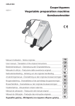
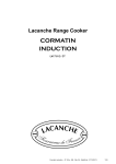
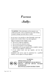
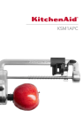
0595J04701
Batteur-mélangeur spécial boulangerie 20/30L
11/2011
Special mixer-beater for bakeries, 20/30L
Planetenrührwerk speziell für
Bäckereien 20/30L
Manuel d’utilisation - Notice originale
User manual - Translation of the original instructions
Bedienerhandbuch - Übersetzung der Originalanleitung
Manuale di utilizzo - Traduzione delle avvertenze originali
FR
GB
DE
IT
Руководство по эксплуатации (перевод)
ES
RU
Manual cu instrucţiuni - instrucţiunile originale
RO
Manual de utilización - Traducción del manual original
A
C
D
E
F
16
07/2007
16
XBB20/30 FR 07 07
XBB20/30 FR 09 05
Refer to the numbered drawings
that go with the numbered paragraphs in the instructions
GB
07/2009
Contents
Introduction
Installation
Use and Safety
Cleaning and hygiene
Fault finding
Maintenance
Compliance with regulations
1
1
3
5
5
6
7
Introduction
The User Manual contains useful information for the user on
how to work correctly and in complete safety, and is designed
to make it easier to use the machine (called “machine” or “appliance” below).
What follows is in no case intended to be a long list of warnings
and constraints, but rather as a series of instructions meant to
improve the service provided by the machine in every respect,
and particularly to avoid a series of injuries or damage to equipment that might result from inappropriate procedures for use
and management.
It is essential that all the people responsible for transporting,
installing, commissioning, using, maintaining, repairing or dismantling the machine should consult this manual and read it carefully
before proceeding with the various operations, in order to avoid
any incorrect or inappropriate handling that might be result in
damage to the machine or put people’s safety at risk.
It is just as important that the Manual should always be available
to the operator and it should be kept carefully where the machine
is used ready for easy and immediate consultation in case of any
doubt, or in any case, whenever the need arises.
If after reading the Manual, there are still any doubts concerning
how to use the machine, please do not hesitate to contact the
Manufacturer or approved After Sales Service provider, who
is constantly available to ensure quick and careful service for
improved machine operation and optimum efficiency.
Note that the safety, hygiene and environmental protection standards currently applicable in the country where the machine is
installed must always be applied during all phases of machine
operation. Consequently it is the user’s responsibility to ensure
that the machine is operated and used solely under the optimum
safety conditions laid down for people, animals and property.
Introduction
1.1 DESCRIPTION
• 3 tools are available as standard supply:
• These electronic beater-mixers are professional bakery and
pastry-making appliances designed for kneading, mixing and
whisking all kinds of food products.
A Stainless steel bowl, 20 or 30 litre capacity
(depending on model)
B Removable safety guard
D Head
E Control panel
G Lift/lower lever
H Planetary gear system
I Column
J Bowl cradle
K Feet
1.1b
A Hook for kneading.
B Paddle for mixing.
C Whisk for emulsions
• Optional equipment:
- 20 and 30 L reinforced whisk for heavy work.
- Reduction bowl 10 L with 3 tools (20 L model)
- Reduction bowl 10/20 L with 3 tools (30 L model)
- Any-gas heater with safety device, rating 3.5 kW
- Electric heater 230 V, 2.6 kW
Installation
ATTENTION!!
Machine storage: -25°C to +50°C
Ambient temperature during operation: +4°C to +40°C
This machine is for professional use and must be used by staff trained to use, clean and maintain it, in terms or reliability and
safety.
Use the machine in adequately lit premises (See applicable technical standard for the country of use. In Europe, refer to standard
EN 12464-1)
When handling the machine, always check that the parts taken hold of are not mobile elements: risk of dropping and injury to the
lower limbs.
The machine is not designed for use in explosive atmospheres.
1
XBB20/30 GB 07 07
2.1 DIMENSIONS - WEIGHT (for information only)
. Handling - Transport
- The beater is delivered fixed to a wooden pallet.
- Use a forklift truck to remove it from the pallet, slipping the
forks beneath the feet.
A Gross weight when packaged:
B Net weight when equipped (kg)
C Package dimensions (mm) L x w x h
D Overall dimensions of machine: L x w x H (mm)
E Dimensions for fitting beater: E x E1 x E2 (mm)
If unloaded manually, take all necessary precautions to ensure
the appliance does not tip at all
2.2 LOCATION
These are exclusively floor-standing beaters.
To chock or level the beater:
- Remove the foot end piece before adjusting.
- Screw with a screwdriver so that the adjustable pad makes
contact.
2.2a
To fix the beater to the floor: fix using the front feet
- Remove the end pieces from the 2 front feet.
- Use a large screwdriver to extract the adjustable feet.
2.2a
- Mark the 2 holes to be drilled (Ø8 max. screw, min. length 80,
plugs not supplied).
2.2b
- Check it is stable by running the beater at high speed with its
beater. Where necessary, the adjustment can be fine-tuned
with the machine running.
- Refit the plug.
2.3 ELECTRICAL CONNECTION
ATTENTION!!
Connection to the electrical power supply must be done according to proper professional practice by a qualified and
authorised person (see current standards and legislation in the country of installation).
If an adapter is used on the socket, a check must be made that the electrical characteristics of this adapter are not lower
than those of the machine.
Do not use multiple plugs
The AC power supply to the machine must comply with the following conditions;
- Maximum voltage variation: ±5%
- Maximum frequency variation: ±1% on a continuous basis, ± 2% over short periods
ATTENTION: the electrical installation must comply (for design, creation and maintenance) with the legal and standard
requirements in the country where used.
- Check that the electric mains voltage, the value shown on the specification plate and the label on the power cable are the same.
- The machine’s electrical power supply must be protected against voltage surges (short-circuits and excess voltages) by
using fuses or thermal relays of the appropriate gauge relative to the place of installation and machine specifications – see
the specifications shown in column F of figure 2.3a
ATTENTION: Concerning protection against indirect contact (depending on the type of power supply provided and
connection of the exposed conductive parts to the equipotential protection circuit), refer to point 6.3.3 of EN 60204-1
(IEC 60204-1) with the use of protection devices for automatic shut-off of power in the event of an insulation fault with
a TN or TT, system, or for the IT system, with the use of a permanent insulation or differentials controller for automatic
shut-off. The requirements of IEC 60364-4-41, 413.1 must apply for this protection.
For example: in a TT system, a differential circuit breaker must be installed upline of the power supply, with a suitable
power cut-off (e.g.: 30 mA) on the earthing installation for the place where it is planned to install the machine.
ATTENTION: Failure to comply with these instructions means the customer runs the risk of machine failure and/or
accidents due to direct or indirect contacts.
• The electronic beaters run on a single phase power supply.
• A standardised 20A, 2 pin + earth wall socket is required.
• Warning for the installer:
This electronic whisk is fitted with a filter which sends any
interference from the mains to earth without going through the
variator. To work properly, the appliance earth connection must
be sound otherwise the interference may go through the variator
and damage it.
• Check that the electric mains voltage, the value shown on
the specification plate and the label on the power cable are the
same.
Note:
The machine can only be used on TN (earthing
to neutral) and TT (earthed neutral) type supplies. Where a machine has to be installed on
an IT (impeding or isolated neutral) supply, there is
a solution which consists of inserting an isolating
transformer and locally putting on the machine on
TN or TT supply.
Must be earthed using the green and yellow wire.
NO EARTH = NO PROTECTION = RISK OF BREAKDOWN
• The machine must be protected by a residual current device
(RCD) and a 16 A fuse.
XBB20/30 GB 07 07
2
Note: The earth values are defined according to the residual
differential current. (See NF C 15100 and PROMOTELEC To PAT test the Electrolux Range of Food Preparation Equipment,
guidelines). Non-compliance with these instructions may the PCB board needs to be disconnected before any test is done.
This is due to the fact that the boards are fitted with a grounding
result in invalidation of the warranty.
diode that can give incorrect result during such a test. Also on
a standard appliance a flash test of 25 amps and up to 3000v is
In certain circumstances depending
used but, as you would expect, to use this on equipment, which
on the sensitivity of the protective cuthas a printed circuit, board would be quite destructive to that
outs, it may be necessary to install
board. We would recommend the use of a PAT tester approved
SI-type (super immunity) devices to
for computer systems which use a lower rate of amps.
prevent untimely triggering.
•
A
C
D
E
F
Electrical characteristics:
2.3a
: Machine
: Supply voltage
: Frequency
: Nominal power
: Rating of the fuse of the mains cable (Amperes) see XBM20.
2.3b
• Check the direction of rotation
- Of the planetary gear, anti-clockwise
(see arrow on head)
or the tool, clockwise
: factory setting.
In the event of a problem, see §5.2 to reverse the direction of
rotation.
The appliance is perfectly safe and is CE certificated. There are
two ways to get overcome this problem.
· Disconnect the board as instructed and test using test for
PC’s,
· Or install the mixer on a fused spur (no plug) as this takes it
away from being a portable appliance and the PAT test is then
not needed.
Use and Safety
ATTENTION!!
Clean the machine properly prior to its first use
Uncontrolled closure of the lid or ram press involves a risk of crushing the fingers.
Never put a hand in the work area while the machine is in operation; risk of injury. It is strictly forbidden to put the safety systems out of action or modify them: Risk of permanent injury!!!!
Check that the safety devices operate correctly each time before using (see paragraph on «safety system checks»).
Never put a hand, a hard or frozen object in the appliance
For health and safety reasons, always use a strong washable or disposable head covering that covers the hair completely.
3.1 OPERATION - SAFETY
• The safety of the user is guaranteed by:
- The motor halting when the safety guard is opened.
- The design of the guard that allows products to be added
perfectly safely during operation.
- The motor halting when the cradle is lowered. It will not start
again when the ON switch is pressed.
- The need to press the ON button after the machine has been
stopped («no volt release» device)
- Protection against current and power surges, drops in power
and the motor overheating.
- Compliance with the instructions given in this manual for using,
cleaning and maintaining the machine.
3.1
• Control panel
A Reduce time setting on timer
B Increase time setting on timer
C STOP button
D START button avec vitesse présélectionnée.
E Timer display
F Increase speed
G Reduce speed
H Speed display
• The beater will start normally when the bowl-holder cradle
assembly is in the working position,
- The safety guard is fitted and down,
- The timer is set on continuous or timed operation.
a)Timed operation
- Select time on E by pressing buttons A and B
- Start by pressing button D
- Stop at the end of the time set, or by pressing button C
Note:
- To change the time being counted down, press on button
C then change using buttons A and B;
-resume cycle by pressing button D.
- The time displayed at the beginning of the cycle remains in
memory
- To permanently interrupt a cycle underway, press button C
twice.
b) Continuous operation
- Select ---- on E by pressing and holding button A
- Start by pressing button D
- Stop by pressing button C
c) Speed variation and pre-selected speeds
Speeds I, II and III (D keys) are programmed in the factory. The
speed can be varied at any time by pressing on keys F and G.
Similarly, the speed can be returned to one of the programmed
settings by pressing on a D key.
• Programming the D keys
- Switch on the power to the appliance
- Start the appliance by pressing button I, II or III depending on
the speed to be programmed
- Adjust the speed using the + and – buttons
- Press and hold the
key on the timer until the speed
display goes out.
- Repeat the operation for each speed (I, II, III)
- The programming is deleted when the power to the appliance
is turned off.
3
XBB20/30 GB 12 08
3.2 FITTING – REMOVING THE SAFETY GUARD
• To refit it:
- Match up the pads with the slots in the ring on the guard.
The rotating safety guard is removable to make cleaning
easier.
• To remove it:
- Stop the machine, lower the cradle, remove the tool and the
bowl.
- The guard is locked in position, so turn it clockwise (1 complete turn) until it reaches the stop
3.2a
3.2b
- Pressing the guard firmly upwards, turn it anticlockwise
(1 complete turn) until it locks in position against the stop (stiff
movement).
Note: The screen holds in place by itself once it has
started to be turned.
- The guard unlocks downwards and comes off by itself.
3.2b
THE BEATER CANNOT START UNLESS THE GUARD IS IN THE
CORRECT CLOSED AND LOCKED POSITION.
THE MIXER CANNOT OPERATE WHEN THE GUARD IS
REMOVED
3.3 FITTING THE BOWL AND TOOLS:
• Proceed as follows:
- Bring the cradle to the lowered position, by pushing lever G
backwards.
- Place a tool inside the bowl.
Note: make sure that the handle bearing surfaces
are clean (see §4-2).
- Push the tool onto the tool holder spindle, then turn it anticlockwise
to lock it in position.
3.3b
§5.3
- Pull lever G towards you to bring the bowl up into the working
position.
- Close the safety guard.
- Press the ON button
- Place the bowl on the cradle.
- Engage the bowl swivel joint in the housing in the cradle and
lower the bowl vertically to position the two pins on the cradle
in the holes of the handles.
3.3a
3.4 CHANGING SPEEDS AND SPEED SELECTION
• The electronic variator offers extremely flexible operation for the
user and a continuous range of speeds, so that all kinds of work can
be carried out under optimum conditions for yield and quality.
• Always start in slow speed 1 to avoid splashing or clouds of
flour and then gradually increase the speed depending on the
work required.
3.4
• Speeds to be used for the tools.
V
Speed of planetary gears (rpm)
A
Firm dough
B
Soft dough
Recommended range for normal work
3.5 MAXIMUM CAPACITIES
• The beater’s working capacity depends upon:
- The tool used.
- The nature, quantity and density of the mass to be worked.
- The optimum speed for quality results.
• Too large a quantity is always detrimental to the quality of
the work and the life of the mechanical parts of the beater
and may result in the motor overheating and abrupt stoppage
(See
§ 5.1).
• Maximum recommended quantities
Products
Bowls (L)
10/20/30
Flour and water paste
(Moisture content 60%)
Kg flour
4/7/10
Pizza
(Moisture content 40%)
Shortcrust pastry
Sweet pastry
Croissant dough
Brioche dough
Choux pastry
Meat
Mashed potato
Fondant
Egg whites
Genoese sponge
Sponges
Meringues
XBB20/30 GB 07 09
References
4
Kg dough
3/6/7
3/6/7
2,5/5/6
Kg flour
3/6/7
2,5/5/6
Litres water
3/6/7
Kg
5/10/15
Kg potatoes
5/10/15
kg sugar
3/6/8
16/32/50
Number of eggs 15/30/45
15/30/45
Kg sugar
0,75/1,5/2,5
Tools
Cleaning and hygiene
ATTENTION!!
Before dismantling any part, disconnect the appliance from the power supply.
Before using any cleaning product, be sure to read the instruction and safety instructions accompanying the product and use
appropriate protective equipment.
Do not clean the machine with a pressure cleaner
4.1 BETWEEN TWO SESSIONS
• Clean the planetary gear housing, the tool holder spindle and the
safety guard with a damp sponge and a detergent - disinfectant
product, then rinse in clean water.
Note: Use cleaning products that are compatible with
the aluminium parts.
• Remove the bowl and tool.
• Using hot water and detergent/disinfectant or degreaser (if working
with greasy products), immerse and wash the inside of the bowl
and the tool in the sink, then rinse in clean water and dry.
4.2 AFTER USE
• Disconnect the machine.
• Remove the bowl, tool and safety guard.
• Clean the bowl and tools with detergent/disinfectant or degreaser in a sink, then rinse in clean water and dry. Only the
bowl may be cleaned in a dishwasher.
• Clean the planetary gear housing, the tool holder shaft, the
safety guard and the cradle, paying particular attention to the
bowl handles and where necessary the outside of the beater
using a damp sponge and a disinfectant/detergent product,
then rinse.
• Check that the different parts have been cleaned correctly.
Note:
- Check that the products used for cleaning are compatible
with the machine part materials.
- Do not use abrasive detergents as these could scratch the
surfaces.
- To clean the accessory appliances, check with the instruction
sheet for each accessory
Do not clean the machine with a pressure cleaner.
• On a regular basis: (at least once a month)
- Remove dust from the ventilation slots at the back of the
machine (cause of overheating).
- Wipe and lightly lubricate the raising and lowering pins with Vaseline.
- Oil the tool-holder shaft (food quality oil or grease).
4.3 STRAY FLOUR PARTICLES:
In order to reduce the emission of stray flour particles while
loading the bowl, it is recommended as follows:
- Do not shake an empty flour bag. Roll it with care.
Keeping to these simple rules will contribute to reducing the
emission of flour dust and consequently reducing the risks of
allergy linked to that dust.
- Empty the flour bag or the container containing the flour without
shaking it.
- Pour in the water before putting the flour in if that is possible
- Always start at slow speed during the water/flour mixing
Fault finding
5.1 THE BEATER WILL NOT START
•
-
Check that:
The machine is plugged in.
The electrical power supply to the socket is correct.
The bowl is in the working position and the safety guard
closed.
• If the beater will still not start:
- Remove the rear plate to check that there is no operating fault
on the variator.
- If «
» or «
» is not displayed, call for a specialist to
intervene.
Comply with the safety instructions, dangerous voltage (See
§5.2).
• If the beater stops during operation:
- The variator heat sensor has been triggered. Wait for a few
minutes before starting again.
- Reduce the speed or the load (see
§ 3.3 and 3.4).
5
XBB20/30 GB 07 07
5.2 ABNORMAL NOISE OR OPERATION
. Reduce the quantity of products (see
§3.4).
. If appropriate, change the tool.
• Speed does not vary
- Faulty control card or wires disconnected or cut.
• Metallic noise
- Tool out of shape, rubbing or rotating backwards
(see
§ 2-3).
- Bowl damaged or not in place (see
§ 3.3).
- Lack of lubrication at planetary gear (see
how to dismantle).
•
•
-
§ 6-2 for
• If the direction of rotation is inverted:
- Disconnect the machine: obligatory.
- Remove the rear plate.
Harsh noise
Faulty belt (see
§ 6-1 for how to replace it or for the tension).
Noisy motor
Motor running on 2 phases. Check the connection and the
electrical circuit (see
electrical diagram §6.4).
Wait for about a minute for effective discharge of the
condensers before intervening inside the variator.
DANGEROUS VOLTAGE.
• Lack of power at the variator
- The electronic variator may limit the power automatically and
remain at a speed below that displayed on the potentiometer
button if:
. The speed selected is too high: risk of the belt slipping and
excessive wear
. There is too much product.
. The tool is not suitable for the work
- Depending on the case, do the following:
. Reduce the speed displayed (see
§3.3).
- Check that the green display lamp on the variator is not lit and
unclip the terminal cover.
- Invert the wires on terminals U and V: an insulated screwdriver
must be used.
- Refit the terminal cover and the rear plate.
- Connect the machine and the check the direction of rotation.
5.3 TOOL JAMMED ON THE TOOL HOLDER SPINDLE
- By tapping the tool with a mallet after clearing the pin from the
bayonet.
- Rub down the distorted part where necessary.
• Generally due to poor cleaning or a distorted tool caused by a
blow.
• If the tool is starting to seize, do not force it. Apply oil or penetrating fluid and wait a few minutes for the product to work.
• Work it gradually, applying measured force:
- Turning it, using a to-and-fro movement.
- Per rotazione, con un movimento di «andata e ritorno».
If the problem persists, contact your local dealer’s service
department.
Maintenance
ATTENTION!!
Unplug the machine before carrying out any operation.
Maintenance may only be carried out by a qualified, trained and authorised person.
6.1 MECHANICAL PARTS
• This beater requires only minimum maintenance (the bearings,
motor and mechanical parts are greased for life).
- Lubricate the planetary gears with a high adhesive grease
(see
§ 6.4).
• At least once a year it is recommended to:
- Clear the ventilation slots if required, they can cause overheating.
- Clean out the belt dust and flour from inside the machine using
a vacuum cleaner.
6.2 CHECK OR CHANGE OF BELT
• Check the belt tension and degree of wear. To check it, proceed as follows:
- Using a small piece of timber apply leverage between the head
and motor support until the device lifts slightly.
6.2
- Tighten the 4 screws while maintaining tension on the belt.
- Disconnect the machine.
- Remove the upper casing to access the transmission.
• If the belt is faulty:
- Check that the tension is correct by pressing with the thumb
and forefinger.
Note: It is absolutely essential to ensure the belt is
properly tensioned. If there is insufficient or excessive
tension, this may cause abnormal functioning of the
transmission or even premature wear to the belt or bearings.
- Loosen by 2 turns the 4 screws fixing the motor onto the
column (size 13 mm spanner).
- Fit a new belt if required and check that the teeth are properly
engaged in the pulley grooves.
XBB20/30 GB 07 07
6
6.4 DISMANTLING THE PLANETARY ASSEMBLY
- Remove the safety guard and the casing, having first disconnected the machine.
6.2
- Remove the belt.
- Place a piece of timber between the bowl and planetary
assembly to hold the latter in place.
6.4
- Remove the driven pulley and its cotterpin.
- Remove the accessory socket if the model has one.
- Remove the planetary assembly by tapping on top of the sun
gear shaft with a mallet, and moving the bowl down as and
when required.
6.5 CHECKING THE SAFETY ELEMENTS
• The safety elements must be checked frequently to ensure
that they operate correctly. The motor should stop when the
safety guard is opened.
• If one of these two functions is not implemented:
- Do not use the machine.
- Have it adjusted by your local dealer’s service department.
6.6 ELECTRICAL COMPONENTS
6.6
See electrical diagrams.
•
-
• Check the condition of the power cable and the electrical
components regularly.
• Wire colour Identification:
- Earth
: (B/C) yellow/green
- Neutral
: (N) blue
- Phase
: (L) brown
- Power circuit : black
Control circuit: red
Component identification:
M : Motor:
S1 : Raise and lower safety
S2 : Removable guard safety device
CDE : Control card
- V
: Electronic variator
6.7 ADDRESS FOR SERVICE REQUIREMENTS
We advise you first to contact the dealer who sold you the
machine.
Dealer’s stamp
For any information or orders for spare parts, specify
the type of machine, its serial number and the electrical
specifications.
The manufacturer reserves the right to modify and make improvements to the products without giving prior warning.
Date of purchase: .............................
Compliance with regulations
The machine has been designed and manufactured in compliance with:
- Machine directive 2006/42 CEE,
- Machine directive CEM 2004/108/CEE,
- 2006/95/EEC: Low Voltage Directive
- 2002/95/EC: Equipment recycling directive
2002/96/CEE « WEEE »
The symbol «
» on the product indicates that this product may
not be treated as household waste. Instead it shall be handed
over to the applicable collection point for the recycling of electrical
and electronic equipment. By ensuring this product is disposed of
correctly, you will help prevent potential negative consequences
for the environment and human health, which could otherwise
be caused by inappropriate waste handling of this product. For
more detailed information about recycling of this product, please
contact the sales agent or dealer for your product, your after-sales
service, or the appropriate waste disposal service.
2006/12/CEE“Waste”
The machine is designed so that it does not contribute, or as
little as possible, to increasing the quantity or harmfulness of the
waste and the risks of pollution.
Make sure to observe the recycling conditions.
94/62/CEE“Packaging and packaging waste”
The packaging for the machine is designed so that it does not
contribute, or as little as possible to increasing the quantity or
harmfulness of the waste and the risks of pollution.
Make sure to eliminate the various parts of the packaging in
appropriate recycling centres.
- European standards:
EN 454-2000 Beater Mixers. Safety and hygiene regulations.
This compliance is certified by:
- The CE compliance mark attached to the machine.
- The relative CE compliance declaration associated with the
warranty,
- This instruction manual, which must be given to the operator.
Acoustic specifications:
- The acoustic pressure level measured in accordance with the
test code EN ISO 3743.1-EN ISO 3744 < 70 dBA.
Protection indices as per the EN 60529-2000standard:
- IP55 electrical controls.
- IP23 overall machine.
Integral safety:
- The machine has been designed and manufactured in compliance with the relevant regulations and standards referred to
above.
- Before using the machine, the operator must be trained in its
use and informed of any possible residual risks .
Food hygiene:
The machine is made from materials that comply with the following
regulations and standards:
- Directive 1935/2005/CEE: Materials and objects in contact with
foodstuffs.
- Standard EN 601-2004: cast aluminium alloy objects in contact
with foodstuffs.
- Standard EN 601-2004: cast aluminium alloys in contact with
7
foodstuffs.
The surfaces of the food area are smooth and easy to clean. Use
detergents that are approved for food hygiene and observe the
instructions for their use.
XBB20/30 GB 07 07
Schéma électrique / Electrical wiring diagram /
Электрическая схема / Schemă electrică
6.6
XBB20/30 FR 01 2011
Q
• Repérage des couleurs fils :
- Terre
:
(B/C) vert/jaune
- Neutre
:
(N) bleu
- Phase
:
(L) marron
- Circuit de puissance : noir
- Circuit de commande : rouge
• Repérage des composants :
- M
: Moteur
- S1 : Sécurité monte et baisse
- S2 : Sécurité écran de protection amovible
- CDE : Carte commande
- V
: Variateur électronique
•
•
-
Wire colour Identification:
Earth
: (B/C) yellow/green
Neutral
: (N) blue
Phase
: (L) brown
Power circuit : black
Control circuit: red
Component identification:
M : Motor:
S1 : Raise and lower safety
S2 : Removable guard safety device
CDE : Control card
- V
: Electronic variator
Electrolux Professionnel SAS - 23200 AUBUSSON - FRANCE