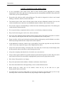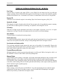
1
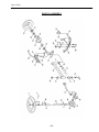
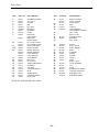
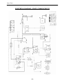
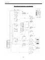
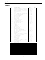
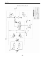
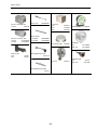
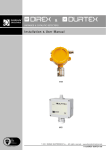
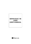
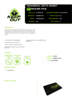
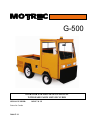
G-500 OPERATOR AND MAINTENANCE MANUAL WITH SPARE PARTS LISTS INCLUDED SERIAL NUMBER : Printed in Canada 2004-07-19 1028117 & UP MOTREC, Inc. Electric & Gas Vehicle One Year Limited Warranty Effective Jan 1, 2005, MOTREC, Inc. (MOTREC) hereby warrants to the Original Retail Purchaser (Owner) that any of its vehicles shall be free from any defect in materials for a period of 90 DAYS while in the possession of such Original Retail Purchaser. This warranty IS NOT TRANSFERABLE to any subsequent Buyer. The warranty period is extended to one year or one thousand (1,000) hours, which ever first occurs, on the electric motor, differential, steering gear and the electronic speed controller. For battery chargers, MOTREC initial 90 days warranty coverage applies. Charger fuses and diodes are not included in this warranty. MOTREC makes no warranty or representation with respect to the internal combustion engine, tires and batteries, since their respective manufacturers cover such parts. Accessories (light, horn, etc), electrical contacts (switch, solenoid, contactor, relay), diodes & fuses, belts & pulleys, filters & spark plugs, lubricants, brake linings & shoes, brake drums & discs, seals, seats, trim and other items subject to wear are not included in this warranty; nor is any item that in MOTREC sole opinion, shows evidence of neglect, misuse, abuse, collision or alteration. This warranty shall not apply to normal maintenance requirements as described in the User Manual, and to damages during shipment. The latter is the carrier's responsibility. No compensation will be allowed for delays To initiate warranty coverage on any MOTREC vehicle, the Dealer must complete and return the “Sales/Installation Report” to MOTREC within 30 days after delivery to the Original Retail Purchaser; or within 90 days after the delivery date to the Dealer, which ever occurs first. Failure to follow these procedures will result in considering the warranty coverage effective as of the shipment date from the factory. The defective vehicle must be returned, at the Owner's expense, to an authorised MOTREC Dealer within 30 days after failure. The Owner will not be charged for parts and labour required for warranty repairs, which must be performed by an authorised MOTREC Dealer only. The vehicle will be returned at the owner’s expense. The Warranty Claim Forms must be completed and returned with the defective part(s) to MOTREC within 30 days after repair was done. No compensation will be allowed for damages caused by vehicle downtime. Operators and service technicians shall read, understand and follow the safety, operating and maintenance instructions in Motrec Manual. Owner is responsible for the training of operators and service technicians. Owner shall comply with OSHA and ASME/ANSI B56 regulations. MOTREC vehicles are designed for off-road use only. MOTREC disclaims any liability for incidental or consequential damages, to include, but not be limited to, personal injury or property damage arising from vehicle misuse, lack of maintenance or any defect in the vehicle. MOTREC prohibits, and disclaims responsibility for, any vehicle modification altering the weight distribution and stability, increasing the speed or affecting the safety of the vehicle. Such modifications can cause serious personal injury or property damage for which MOTREC disclaims any responsibility. The following additional conditions apply to Owners that are located outside North America: − The warranty period starts the date of shipment from the factory. − The defective parts must be returned at the Owner's expense to MOTREC prior to warranty repair. − Battery chargers are covered by their respective manufacturers. TABLE OF CONTENTS INSTRUCTIONS 3 SAFETY WARNINGS FOR OPERATORS VEHICLE CONTROLS (HYDRAUSTATIC – KUBOTA) MAINTENANCE 4 5 6 SAFETY WARNINGS FOR SERVICE TECHNICIANS PERIODIC MAINTENANCE CHECKLIST - HYDRAUSTATIC (KUBOTA) OIL GRADE CHART HYDRAULIC BRAKES FRONT AXLE AND STEERING SPARE PARTS 7 8 9 10 11 12 BODY, CAB, SEATS, TIRE HYDROSTATIC DRIVE, REAR AXLE AND SUSPENSION ENGINE MUFFLER & MOUNTING, KUBOTA DIESEL BRAKE CONTROLS FRONT ASSEMBLY ELECTRICAL DIAGRAM – START / CHARGE CIRCUIT ELECTRICAL DIAGRAM – TRANSMISSION / ENGINE MANAGEMENT ELECTRICAL DIAGRAM – ACCESSORIES HYDRAULIC DIAGRAM MOTREC ILLUSTRATED ACCESSORIES -2- 13 14 16 18 19 21 22 23 26 28 Instructions INSTRUCTIONS -3- Instructions SAFETY WARNINGS FOR OPERATORS It is the responsibility of the owner of this vehicle to ensure that the operator understands the operating characteristics of this vehicle, and obeys the following safety rules and guidelines (ANSI B56). Do not drive this vehicle unless you are a qualified operator. Do not drive this vehicle on public roads and highways. This vehicle is designed to be driven in and around buildings, warehouses, factories, nurseries and resorts. The electrical system of this vehicle will make sparks which can ignite inflammable materials. Never use the vehicle in hazardous areas where there are inflammable materials, explosive dust or fumes in the air. Never run the engine in a closed building or confined area and avoid inhaling engine fumes. The exhaust gases contain poisonous carbon monoxide. Do not open the battery compartment unless you have received battery maintenance training. Keep clear from moving parts such as tires, sheaves and motor. Never carry more passengers than the number allowed for this vehicle. Wait until all occupants are seated to start. Always keep all body parts inside the vehicle. Keep both hands on the steering wheel. Do not exceed the vehicle cargo load capacity and gross trailing weight capacity, rated for flat hard even surface. Different operating conditions such as ramps reduce vehicle capacities. Avoid unbalanced or top-heavy loads to keep a good stability. Do not load cargo that can easily fall off the vehicle. Do not carry cargo that is longer, wider or higher than this vehicle. Always slow down before turning. Avoid sharp turns. The vehicle may overturn easily if turned sharply when driving, especially when on an incline or when carrying a heavy load. Always drive straight up and down the face of an incline, never across the face. Always reduces speed to half the level ground maximum speed while driving down an incline. Keep the vehicle under control at all times. Be aware that the stopping distance greatly increases going down an incline. Drive slowly if the ground is wet or slippery. Keep to the right under normal conditions. Maintain a safe distance from all objects. Slow down and sound the horn when approaching a corner or other blind intersections. Before leaving the vehicle, turn off all switches, remove the key, set the shift lever to park.. Do not park the vehicle on an incline. Use another driver to steer this vehicle while it is towed. Be sure the driver uses brakes when you slow or stop the towing vehicle. Do not exceed 5 MPH or carry any passengers while towing this vehicle. -4- Instructions VEHICLE CONTROLS (HYDRAUSTATIC – KUBOTA) Fuel Tank The fuel tank is located on the right (G500) or rear (G660). Do not remove the fuel cap while the engine is running. Do not fill the fuel tank to point of overflowing. Use clean, fresh, lead-free gasoline intended for automotive use. A minimum of 85 octane is recommended. Do not mix oil with gasoline. Engine Oil Check the oil level when the engine is not running. Kept clear from moving parts, pulley, belt. Hydraulic oil tank The hydraulic oil tank is located on the left side. Do not remove the oil cap while the engine is running. Do not fill the oil tank to point of overflowing. Use hydraulic oil meeting ISO VG-46 Oil sentry When the red light on the instrument panel turns on, the engine oil pressure is too low, or engine temperature is to high. Therefore, the engine must be serviced to avoid serious damage. Horn button The horn button is located on the steering column. Park brake lever To actuate the parking brake, depress the brake pedal and pull up the hand lever located between the front seats. Never park on an incline. Always set the parking brake before leaving the vehicle. Accelerator and brake pedals The accelerator and brake pedals operate the same way as the pedals of an automobile. Depress the accelerator pedal with the right foot to speed the vehicle up and release it to slow down. Depress the brake pedal with the right foot to reduce the vehicle speed. Forward/Reverse Selector Shift only when the vehicle is not moving and engine is at idle speed. Before leaving the vehicle, set the FWD/REV selector to NEUTRAL and set the parking brake. Manual Choke GAS ENGINE: before starting a cold engine, pull out the choke knob and depress the accelerator pedal halfway to the floor; as the engine warms up, push the knob in until the engine responds properly. LPG ENGINE: before starting the engine, pull out the choke and depress the accelerator pedal halfway to the floor; while starting, after two seconds, push the knob halfway; as the engine warms up, push the knob in until the engine responds properly. Key switch / starter Before starting, set the F/R selector in NEUTRAL. To avoid starter damage do not crank the engine continuously for more than 10 seconds at a time; wait 60 seconds before attempting to start again. Remove key from key switch before leaving the vehicle. -5- Maintenance MAINTENANCE -6- Maintenance SAFETY WARNINGS FOR SERVICE TECHNICIANS It is the responsibility of the owner of this vehicle to ensure that the service technicians are properly trained and obey the following safety rules and guidelines (ANSI B56). Maintenance operations must be made by properly trained service technicians. Before any maintenance work, park the vehicle on a flat level surface, set the shift lever to park, turn off all the switches, remove the key, lift the wheels off the ground and secure with jack stands of adequate capacity. Keep clear from moving parts such as tires, sheaves, drive shaft and motor. Follow the maintenance instructions applicable to the type of repair, maintenance, or service. Always wear a face shield and gloves when working around batteries. Before opening the battery compartment, turn off all switches and remove the key. Batteries emit highly explosive gases which greatly increase when charging; do not disturb connections or produce sparks around batteries to avoid a battery explosion and acid splashing. Battery acid causes severe damage to eyes or skin. Flush contaminated area immediately with water. Use insulated tools to avoid sparks that can cause battery explosion and acid splashing. Use two counteracting tools, double-wrench technique, when disconnecting or tightening terminals on the battery and the speed controller to avoid cracking the terminal or battery post welds. Keep cables and wires clear from mechanical and rubbing action. Make sure cable covering is free from cutting or visible damage. Before replacing a fuse or circuit breaker, identify the cause of failure and repair. Always ensure the integrity of the warning labels. If they suffered damage and are not readable, replace them promptly. The following images depict the dashboard and general security warning labels: -7- Maintenance PERIODIC MAINTENANCE CHECKLIST - HYDRAUSTATIC (KUBOTA) ! WARNING ! Maintenance operations must be made be properly trained service technicians. Keep clear from moving parts such as tires, sheaves and motor. Keep cables and wires clear from mechanical and rubbing action Batteries contain sulphur acid that can cause severe burns on skin or eyes. When working around batteries, wear acid proof protective equipment: face shield and gloves. Use electrically insulated tools to avoid sparks that can cause battery explosion. Before any maintenance work, park the vehicle on a flat level surface, turn key switch to OFF, lift the wheels off the ground and secure with jack stands of adequate capacity. PERIOD CHECK/PERFORM HOURS MECHANICAL DAMAGE ALL ACCESSORIES ENGINE OIL LEVEL HYDRAULIC OIL LEVEL use clean oil ISO VG46 ENIGINE COOLANT LEVEL THROTTLE CONTROLS TIRE PRESSURE, pressure rating on tire MASTER CYLINDER FLUID LEVEL (DOT 3) BRAKE PEDAL TRAVEL 2 inches (5 cm) maximum travel STEERING FOR PLAY PARKING BRAKE LEVER normally requires 20 lbs.(10 kg) force to apply CHANGE OIL IN A NEW ENGINE AIR FILTER ELEMENTS SPARK PLUGS, clean/adjust or replace, if applicable ENGINE OIL CHANGE ENGINE OIL FILTER CHANGE CLEAN RADIATOR, remove cooling shrouds and clean cooling areas, clean oil cooler fins if applicable. EXHAUST SYSTEM for leak HYDR. BRAKE LINES FOR LEAK BRAKE MECHANICAL LINKAGES for wear & play BRAKE LININGS FOR WEAR 0.05 in.(1 mm) minimum lining thickness. GREASE brake pedal pivots, steering column, ball joints and kingpins. FRONT WHEEL BEARINGS PLAY TIGHTEN NUTS/BOLTS electric term.; drive; steering; brakes; suspension; body. IGNITION TIMING, check and adjust, if applicable CLEAN AND RE-PACK FRONT HUBS CHANGE TRANSMISSION OIL FILTER CHANGE TRANSMISSION OIL, (ISO VG46) -8- DAY 50 QUART. 200 YEAR 1000 X X X X X X X X X X X X X X X X X X X X X X X X X X X X 2-YEAR 2000 Maintenance OIL GRADE CHART Vehicle system Oil grade FORD engine Single Viscosity 10°F to + 60°F +10°F to + 90°F Above +32°F Above +50°F *10W 20W / 20 30 40 Multi-Viscosity Below +10°F Below +60°F +10°F to 90°F Above 10°F Above +20°F *5W-20 5W-30 10W-30 10W-40 or 10W-50 20W-40 or 20W-50 Automatic transmission Differential KUBOTA engine Above 77°F +32°F to 77°F Above +32°F Note DEXTRON 3 80W90 30 or 10W-30 or 10W-40 20 or 10W-30 or 10W-40 10W or 10W-30 or 10W-40 Hydraustatic transmission ISO VG46 Common Brakes DOT 3 DMVSS116 standard -9- Maintenance HYDRAULIC BRAKES DRUM BRAKES Remove brake drums and check linings wear; the linings should have a thickness exceeding 1/16" (1.5 mm). Turn the brake adjustment to reduce the clearance between lining and drum but avoid contact or drag when the wheels are turned and the pedal is released. DISC BRAKES Check pad linings for excessive wear; the linings should have a thickness exceeding 1/16" (1.5 mm). Disc brakes are self-adjusting. BRAKE PEDAL If the brake pedal becomes soft or spongy, air may have entered the hydraulic system and the brake system has to be bled: 1. fill the master cylinder with brake fluid (DOT-3); 2. bleed front callipers one at a time by having someone applying a steady pressure on the brake pedal, and close the bleeder before allowing the brake pedal to return to up position; 3. fill the master cylinder with brake fluid (DOT-3); 4. bleed rear wheel brakes one at a time, following the same procedure; 5. fill the master cylinder with brake fluid (DOT-3); 6. clean every fitting and line, remove traces of oil; 7. apply a continuous pressure on the brake pedal for about five minutes ; 8. Finally, inspect brake lines and fittings for leaks ; - 10 - Maintenance FRONT AXLE AND STEERING ! CAUTION ! Before maintenance, turn off all switches, set to neutral, set parking brake, remove the key, and raise the front end of the vehicle supporting it with two jack stands of adequate capacity STEERING INSPECTION Check tire inflation pressure, suspension components, tie rods straightness, tie rod ends play (wear), play (wear) in wheel bearings, kingpins and bushings. REPLACING & ADJUSTING THE STEERING GEAR Remove the pitman arm; The steering box makes 6.5 turns, center the steering gear (3.25 turns from either side); Align the front wheel straight. Install the pitman arm. BACKLASH ADJUSTMENT OF THE STEERING GEAR Center the steering gear (3.25 turns from either side); Adjust backlash of the steering gear using the screw on its side until a slight resistance is felt in the steering wheel when turning near its central position, turn CW to remove all lash; Tighten the lock nut on the screw to 25 lbft. TOE-IN ADJUSTEMENT With the wheels in straight forward direction, measure the inside (left to right) distance between the front tires, at the front and rear of the tires; Turn the rear tie rod until the distances are equal and tighten the two lock nuts on the tie rod. REMOVING & GREASING OF FRONT HUBS, required once-a-year Remove dust cap and cutter pin, unscrew nut, remove hub; Inspect bearings and races for wear and replace worn bearings; Replace the seal; Pack the hub with wheel bearing grease and re-assemble. ADJUSTING FRONT HUBS Tighten spindle nut to 30 ft-lb to seat the bearing and back off the nut to the next slot; Install a new cutter pin and the dust cap. - 11 - Spare Parts SPARE PARTS - 12 - Spare Parts BODY, CAB, SEATS, TIRE REF DESCRIPTION 1 SEAT BUCKET SEAT ON SLIDE ADJUSTERS GAMMER SEAT GARMMER SEAT WITH SWITCH 2 BACKREST 3 FRONT COWL BUMPER 4 MOTOR COVERT MOTOR COVERT WITN REAR PANEL BOX 5 5.7 x 8 L.R.B. WHEEL ASS 6 25 x 8.5x 14 L.R.D. WHEEL ASS 7 STEEL CAB AND DOORS STEEL CAB RIGHT DOOR LEFT DOOR DOOR GLASS LEFT DOOR GLASS RIGHT PART # REF DESCRIPTION 480001 1005003 PADDLE LATCH CATCH HANDLE OPENING HANDLE OPENING BAR RIGHT HINGES LEFT HINGES REAR VIEW MIRROR SIDE MIRROR MIRROR BRACKET FIXE MIRROR BRACKET FOLDING WIPER KIT WIPER MOTOR 12V ARM WIPER 2205001 2205002 3605008 2315320001 2330501001 2330501007 300022 5007002 2360320005 2360320006 2360320007 2360320008 2367320003 2367320004 - 13 - PART # 2803000003 3602024 2366320001 2366320003 2366320004 2365000001 2365000002 480039 480040 2399300014 2399300009 366211K 3113000001 2800000001 2800000002 Spare Parts HYDROSTATIC DRIVE, REAR AXLE AND SUSPENSION - 14 - Spare Parts REF DESCRIPTION 1 2 3 4 5 6 7 8 9 10 11 12 13 14 15 16 17 18 19 20 WHEEL NUTS ½-NF SPACER DISC COTTERPIN NUTS HUB STUD ½-NF x 1 ¾ BOLT ½-NF x 2 ½ LOCK WASHER 1/2 CABLE STOP BOLT M12 x 1.75 SHOCK ABSORBER LEAF SPRING, REAR SHACKLE LINK RUBBER BUSHING 48” O.W. HOUSING 54” O.W. HOUSING BOLT 5/8-NC x 3 1/2 LOCK NUT 5/8-NC MOUNTING PLATE NUT ½-NF PART # 2407006 5007001 481433 5080001 5020006 2820007 5016001 242621 5040003 6640001 242602 2177501001 6674013 REF DESCRIPTION 29 30 31 32 33 34 35 36 37 38 39 40 41 42 50 52 60 2185501001 - 15 - ½ NPT PLUG HYDRAULIC OIL TANK MOTOR HOSE OUTLET HOSE SUCTION HOSE RETURN HOSE OUTLET HOSE HYDROSTATIC PUMP FILTER FILTER FITTING BOLT 5/8-NF x 3 1/2 BOLT ½-NF x 10 RIGHT CALIPER LEFT CALIPER PADS FLEX. HOSE SPECIFY VEHICLE SER. NO HYDRAULIC MANIFOLD SPECIFY VEHICLE SER. NO HYDRAULIC PUMP PART # 5074008 4120501005 4120501001 4120501004 4120501003 4120501002 5074009 5074015 4220000004 5016002 5016003 5016004 481432 4110501002 50740014 Spare Parts ENGINE MUFFLER & MOUNTING, KUBOTA DIESEL - 16 - Spare Parts REF DESCRIPTION 1 2 3 4 5 6 7 8 9 10 11 12 TURBO PRECLEANER TURBO PRECLEANER HOLDER FLEX COUPLING AIR FILTER BOX AIR FILTER FILTER PROTECTOR ( TUBE ) FILTER PROTECTOR ( BOX ) ELBOW HOSE HEATHER HOSE HOSE ADAPTOR - HEATHER DIFFUSER FITTING RADIATOR RADIATOR HOLDER RESERVE TANK - PRESTONE ELECTRIC FAN PART # REF DESCRIPTION 6650001 2169501018 2912000003 5080012 6650005 2169501005 2169501007 2912000002 6690002 6690001B 2819501002 6690001D 2819501007 6650018 2169501001 2604501002 5069004 - 17 - 13 14 15 16 17 18 19 20 21 22 23 24 25 90° DEGRES EXHAUST EXHAUST GASKET CATALITIC MUFFLER MUFFLER HOLDER RUBBER MOUNT MUFFLER MOTOR SUPPORT - REAR MOTOR SUPPORT – FRONT H.D. RUBBER MOUNT OIL FILTER FLYWHEEL MOTOR COUPLING PUMP COUPLING ADAPTOR – MOTOR/PUMP PART # 1E01912192 2157501001 2169501023 2169501026 2160501002 2160501006 2160124001 2153501001 6650024 6650010 6650009 6650008 Spare Parts BRAKE CONTROLS REF PART NO DESCRIPTION QTY REF PART NO 1 5 242800 242816 RUBBER SPRING 1 1 14 15 6685001 ACCELERATOR PEDAL CALL ACCELERATOR CABLE FACTORY 1 1 6 7 8 9 10 11 12 2131501001 262807 242817 LEVER PIVOT LUBRICATING FITTING CLEVIS PIN 3/8 X 1 YOKE MASTER CYLINDER BOLT 3/8-NC X 3 1 2 1 1 1 1 2 30 31 32 33 3616013 162831A 5016001 3016004 1 2 2 2 122813 362805 - 18 - DESCRIPTION 8 in. HANDBRAKE LEVER CABLE CABLE STOP CABLE RETAINER QTY Spare Parts FRONT ASSEMBLY - 19 - Spare Parts REF PART NO DESCRIPTION REF PART NO DESCRIPTION 1 2 3 4 5 6 7 8 9 481451 481452 481453 481454 3030021 3030020 481457 481458 401409 STEERING WHEEL NUT 3/4-16 COVER PIN OIL SEAL BUSHING BUSHING TUBE ROD END LEFT HAND ROD END RIGHT HAND NUT, LEFT HAND NUT, RIGHT HAND FRONT TIE ROD REAR TIE ROD RIGHT SPINDLE RIGHT SPINDLE LEFT SPINDLE LEFT SPINDLE AXLE BEAM KING PIN NUT 3/4-NF THRUST BEARING BUSHING OIL SEAL TAPER BEARING HUB WHEEL BOLT TAPER BEARING DUST CAP 25 481431 481430 481432 481433 361425 4840001 RIGHT CALIPER LEFT CALIPER FLEX. HOSE DISC U-BOLT LEAF SPRINGS LEAF SPRING (4000 lbs.) NUT 1/2-NF BOLT 5/8-NC SHACKLE LINK BUSHING NUT 5/8-NC 401423 10 11 11A 12 13 14 15 16 17 19 20 21 22 23 24 481435 481436 481459 481460 481461 481462* 481463 481472* 481464 481413 481473 481414 481437 361417 361418 361419 361420 361421 361422 26 27 28 29 30 31 32 33 34 36 37 38 39 40 41 42 43 44 45 46 47 48 49 50 *Front axle with hydraulic disc brakes - 20 - 481439 242602 3640002 481434 481442 481440 481441 481465 481466 481467 481468 481470 481471 481438 481474 261422 3614002 3614003 PLATE BOLT, LONG BOLT, SHORT BOLT WASHER SHAFT SCREW GEAR ARM BOLT 7/16-NC LOCK WASHER NUT PADS STEERING SUPPORT CASTELLATED NUT BUSHING, LONG BUSHING, SHORT Spare Parts ELECTRICAL DIAGRAM – START / CHARGE CIRCUIT - 21 - Spare Parts ELECTRICAL DIAGRAM – TRANSMISSION / ENGINE MANAGEMENT - 22 - Spare Parts ELECTRICAL DIAGRAM – ACCESSORIES - 23 - Spare Parts PARTS LIST NO DESIGNATION REF QTY B1 B2 B3 B4 B5 B6 B7 E1 E2 E3-E4 E5-E6 E7-E8 F1 F2-F3 F4 F5-F6 G1 G2 H1 H2 H3 K1 K2 K3 M1 M2 M3 M4 M5 P1 P2 P3 P4 P5 R1 R2 S1 S2 S3 S4 S5 S6 S7 S8 S9 Y1 EMERGENCY THERMAL SWITCH EMERGENCY PRESSURE SWITCH THERMAL SWITCH, COOLING FAN REVERSE ALARM HORN COOLANT TEMPERATURE SENDER OIL PRESSURE SENDER GLOW PLUG TIMER STROBOSCOPE HEAD LAMP SIDEMARKER TAIL/BRAKE LIGHT AGC FUSE HOLDER IN-LINE FUSE HOLDER CIRCUIT BREAKER DIODE ALTERNATOR BATTERY GLOW PLUG LAMP CHARGE LAMP EMERGENCY LAMP RELAY 12V, F/R INTERUPT RELAY 12V, MOTOR MAINTAIN FLASHER RELAY STARTER INTERNAL COMBUSTION MOTOR RADIATOR COOLING FAN CAB HEATER FAN WIPER MOTOR FUEL GAUGE VOLTMETER ENGINE COOLANT TEMP GAUGE OIL PRESS GAUGE HOUR METER GLOW PLUGS FUEL SENDER IGNITION SWITCH SEAT SWITCH FORWARD/REVERSE SELECTOR FREEWHEEL SWITCH HEADLIGHT SWITCH HORN BUTTON BRAKE SWITCH TURN SIGNAL SWITCH CAB HEATER SWITCH FUEL SOLENOID VALVE (ENGINE) 16222-83040 3109501001 TS156 246051 246003 100183S 100173S 3690007 3069012 3069020 2469021 5069005 4890028 3107000001 367012 246212 246212 3069010 3127501001 3064004 5069004 6690002 3113000001 686203 3069007 100183 100173 3069008 686207 1E01363591 3109000003 266211 55017 1269004 246210 246207 246050 55017 - 1 1 1 1 1 1 1 1 1 2 2 2 1 2 1 2 1 1 1 1 1 1 1 1 1 1 1 1 1 1 1 1 1 1 1 1 1 1 1 1 1 1 1 1 1 1 - 24 - Spare Parts Y2 Y3 Y4-Y5 Y6 X1 X2 X3 GLOW PLUG SOLENOID HYDRAUSTATIC DISTRIBUTOR FREEWHEEL VALVE FREEWHEEL BLOCK KIT COOLING FAN SOLENOID ALTERNATOR CONNECTOR FUEL VALVE CONNECTOR GLOW PLUG TIMER CONNECTOR - 25 - 246101 SV16-23 4110501003 246101 - 1 1 2 1 1 1 1 1 Spare Parts HYDRAULIC DIAGRAM - 26 - Spare Parts PARTS LIST NO 1 2 3 4 5 6 7 8 9 10 DESIGNATION MACHINE START-UP ADJ. SCREW POWER LIMITER ADJ. SCREW MIN. CHARGE PRESSURE ADJ. SCREW CHARGE PRESSURE ADJ. SCREW HYDROSTATIC VALVE HYDRAULIC MOTOR DIESEL ENGINE 42HP HYDRAUSTATIC PUMP FREEWHEEL MANIFOLD FREEWHEEL SOLENOID - 27 - REF QTY 5074017 Contact manuf. 5080007 5070014 4110501003 SV16-23 0 2 1 1 1 2 Spare Parts MOTREC ILLUSTRATED ACCESSORIES Strobelight, polemount Amber 12-80V: 3690007 Red 12-80V: 2469001 Blue 12-80V: 3690008 Red Tail/Brake light Housing: 3069012R Bulb 12V: 3117240001 Headlight Left: Right: Bulb H/L: Bulb Turn: Bulb Mark: 3111480009 3111480010 3111480011 3111480012 3111480013 Horn button VIP 2330014 Horn button, column mount 246210 Strobelight, cab mount Amber 12-48V: 3116250001 Red 12-48V: 3069026 Blue 12-48V: 3069014 Amber 72-80V:3116720001 Red 72-80V: 3116720002 Blue 72-80V: 3116720003 Back-up lamp Grommet: 12V: 24V: Turn signal switch 246050 3269001 3669012 3669012A Horn button, dash mount 266210 Clear lamp 12V: Bulb 12V: 3069012 1269008 Analog Voltmeter 12V : 3069007 24V : 2469002 36-48V : 3669002 Horn button 3109250001 Amber turn lamp 12V: 3069020 Bulb 12V: 3069021 Pedestral head lamp 12V: 2569001 Bulb 12V: 2569001B Bulb 24V: 4469001 Red Tail/Brake light Grommet: 3269001 Plug: 246012A 12V : 2469021 24V : 2469022 Red Tail/Brake light 12V: 386002 Headlight Left: Right: Bulb H/L: Bulb Turn: Bulb Mark: 3111480003 3111480004 3111480006 3111480008 3111480007 Limit switch HOBBS Gauge 24V: 36V: 48V: 3030015 2469026 3069038 4869037 Back-up alarm 12-48V : 246051 72-80V : 3105720001 Horn 12V: 24V: - 28 - 246003 246013 Spare Parts Wiper arm 2800000001 DC-DC converter, 10A 12-48V: 3069019 DC-DC Converter, 25A 12-48V: 3124000002 72-80V: 3124720001 Wiper motor 12V: 24V: 366211 486211 Wiper blade 14” Blade: 18” Blade: Cab heater 12V: 36V: 48V: 4869018 3669008 4869020 12V Dome light 3669006 Headlamp 12V:3111250001 2800000001 2800000002 Headlamp 12V: Bulb 12V: 3111300001 3111300002 Pantograph wiper arm 246233A 12V Fan Pantograph wiper blade 246233 - 29 - 3669013 Red Pilot light 12V: Bulb 12V: 246212 246212B