1
Teagasc/IMQCS
Recommendations
for the installation and
testing of milking
machines
1
Table of Contents
Recommendations for the installation and testing of milking machines
1
1.1
1.2
Performance requirements.................................................................. 8
Tests for compliance............................................................................ 9
Access for measurements................................................................... 9
1.2.1
General.................................................................................... 9
1.2.2
Airflow measuring connections............................................ 9
1.2.3
Vacuum measuring connections........................................... 10
1.2.4
Additional IMQCS requirements for test points and
isolation valves....................................................................... 11
2.
Safety and hygiene ............................................................................. 12
3.
3.1
Materials............................................................................................... 14
Additional IMQCS requirements for materials
4.
4.1
4.2
4.3
User’s manual......................................................................................
General.................................................................................................
Installation details................................................................................
Instructions for use..............................................................................
5
5.1
5.2
Vacuum system.................................................................................... 18
General.................................................................................................. 19
Vacuum regulation............................................................................... 19
5.2.1 Vacuum deviation................................................................... 19
5.2.2 Regulation sensitivity............................................................. 19
5.2.3 Regulation loss....................................................................... 19
5.2.4 Regulation characteristics and effective reserve.................. 20
Vacuum pumps.................................................................................... 20
5.3.1 Vacuum Pumps - general....................................................... 20
5.3.2 Influence of altitude................................................................ 20
5.3.3 Exhaust.................................................................................... 20
5.3.4 Prevention of reverse flow through vacuum pump............. 20
5.3.5 Location................................................................................... 20
5.3.6 Additional IMQCS requirements for vacuum pumps.......... 21
5.3.7 Additional IMQCS requirements for exhausts..................... 21
Vacuum regulator................................................................................. 21
5.4.1 Regulator leakage................................................................... 21
5.4.2 Vacuum regulator.................................................................... 21
5.4.3 Examples of location of sensing points for vacuum
regulator.................................................................................. 21
5.4.4 Additional IMQCS requirements for vacuum regulators.... 22
5.5
Vacuum gauge........................................................................ 22
5.5.1 Vacuum gauge general........................................................... 22
5.5.2 Mounting................................................................................. 22
Airlines.................................................................................................. 22
5.6.1 Airlines-general....................................................................... 22
5.3
5.4
5.6
2
16
17
17
17
5.7
5.8
5.9
5.10
6.
6.1
6.2
6.3
6.4
7.
7.1
7.2
7.3
7.4
7.5
7.6
7.7
7.8
7.9
7.10
7.11
7.12
7.13
8.
8.1
8.2
8.3
8.4
8.5
8.6
8.7
8.8
8.9
8.10
8.11
5.6.2 Airlines-internal diameter and airflow.................................. 22
5.6.3 Additional IMQCS requirements for airlines........................ 22
Interceptor............................................................................................. 23
Sanitary trap......................................................................................... 23
Leakage into the vacuum system....................................................... 23
Additional IMQCS requirements for sanitary trap(s)........................ 23
Pulsation system.................................................................................. 24
Design data that shall be included in the user’s manual.................. 25
Pulsator airline..................................................................................... 25
Pulsation rate, pulsator ratio and pulsation chamber
vacuum phases.................................................................................... 25
Additional IMQCS requirements for pulsation systems................... 26
Milk system.......................................................................................... 28
General.................................................................................................. 29
Design of milklines............................................................................... 29
Additional IMQCS requirements for milklines.................................. 29
Additional IMQCS requirements for washlines-milkline plants....... 30
Additional IMQCS requirements for milk transfer linesrecording jar plants.............................................................................. 31
Additional IMQCS requirements for milking vacuum
/wash lines-recording jar plants.......................................................... 31
Additional IMQCS requirements for milk recording equipment...... 32
Air leakage............................................................................................ 32
Drainage................................................................................................ 32
Milk inlets.............................................................................................. 32
Diversion of milk.................................................................................. 32
Receiver................................................................................................. 32
Releaser................................................................................................. 33
7.13.1 General.................................................................................... 33
7.13.2 Control of releaser milk pumps............................................. 33
7.14
Delivery line............................................................................ 33
Milking unit.......................................................................................... 34
General................................................................................................. 35
Teatcup.................................................................................................. 35
Additional IMQCS requirements for milking clusters....................... 35
Teatcup attachment.............................................................................. 35
Teatcup removal................................................................................... 35
Vacuum shut-off................................................................................... 36
Air vent and leakage............................................................................ 36
Vacuum in the milking unit................................................................. 36
Milk recording equipment................................................................... 37
8.9.1 General.................................................................................... 37
8.9.2 Recorder jars........................................................................... 37
Attachments to the milking unit.......................................................... 37
Long milk tubes.................................................................................... 37
3
9.
9.1
Cleaning................................................................................................ 38
Additional IMQCS requirements for milk pumps and milk filters.... 39
10.
10.1
Vacuum system- Mechanical tests (ISO 6690)................................... 40
General requirements and preparation.............................................. 42
10.1.1 General..................................................................................... 42
10.1.2 Preparation before testing...................................................... 42
Vacuum regulation............................................................................... 42
10.2.1 Test of vacuum regulation deviation..................................... 42
10.2.2 Regulation sensitivity............................................................. 42
10.2.3 Regulation loss........................................................................ 42
10.2.4 Tests of regulation characteristics......................................... 43
10.2.5 Effective reserve for milking.................................................. 44
Vacuum pumps..................................................................................... 44
10.3.1 Vacuum pump capacity.......................................................... 44
10.3.2 Vacuum pump exaust back pressure.................................... 44
Vacuum regulator leakage................................................................... 44
Vacuum gauge error............................................................................. 44
Vacuum drop in airline......................................................................... 45
Leakage in vacuum system................................................................. 45
10.2
10.3
10.4
10.5
10.6
10.7
11.
11.1
Pulsation system.................................................................................. 46
Pulsation rate, pulsator ratio, pulsation vacuum
phases and vacuum drop in pulsator airline..................................... 47
12.
12.1
12.2
Milk system........................................................................................... 48
Slope of milkline................................................................................... 49
Milk system leakage............................................................................. 49
13.
13.1
13.2
13.3
13.4
13.5
Milking unit........................................................................................... 50
Teatcup or cluster fall-off air inlet....................................................... 51
Leakage through shut-off valves of milking units............................. 51
Air vent and leakage into teatcup or cluster...................................... 51
Measuring the vacuum in the cluster................................................. 51
Measurement of the vacuum drop from accessories
attached in the long milk tube............................................................. 51
Airflow at the end of the long milk tube............................................. 52
13.6
Tables 53
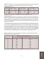
Table 1 - Midi-level milkline plants with two stalls/unit................................ 54
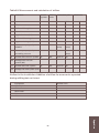
Table 2 - Midi-level recording jar plants with two stalls/unit........................55
Table 3 - Double up low level milkline plants with one stall/unit................. 56
Table 4 - Double up midi-level milkline plants with one stall/unit............... 57
Table 5 - Double up midi-level recording jar plants with one stall/unit....... 58
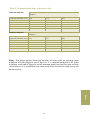
Table 6 - Recommended sizes of diversion line............................................ 59
Appendices
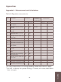
Appendix A - Measurements and calculations.............................................. 61
Appendix B - Test report and inspection - service check list......................... 67
Appendix C - Laboratory and parlour tests of vacuum in the milking unit. 76
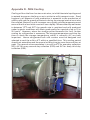
Appendix D - Milk Cooling.............................................................................. 80
4
Recommendations
RECOMMENDATIONS
FOR THE INSTALLATION
AND TESTING OF
MILKING MACHINES
5
Introduction
Recommendations
Recommendations for the installation and testing
of milking machines
Introduction
This manual has been prepared by the Irish Milk Quality Co-Operative Society
(IMQCS). IMQCS has its registered office at 84 Merrion Square, Dublin 2. The
organization was incorporated in 1989 with the aim to improve milk quality
standards in Ireland, to ensure that Irish milking machine installation and
testing standards exceed the best international standards.
This manual combines Irish Milk Quality Co-operative Society (IMQCS)
Guidelines and ISO standards (International Standards Organisation) (ISO
5707 (2007), ISO 6690 (2007) and ISO 3918 (2007) into a reference guide for
all milking machine installers and advisers in the Republic of Ireland. The
manual also contains information on some equipment and topics related to
milking machines which are outside the scope of the ISO standards. The
IMQCS guidelines and ISO standards have been developed to ensure best
practice in the installation and testing of milking machines and are not a legal
requirement.
The basis of the manual is compliance with existing standards, directives and
legislation and agreed installation practices for the fitting of new milkline and
recorder parlour plants for bovines.
The manual applies only to the main milking facility (which is usually a
parlour) and does not apply to new bucket plants. Where possible and
practicable the recommendations shall be applied to existing installations.
The IMQCS has informed each person who is listed in its Register of Certified
Milking Machine Testers and Installers of the importance of complying with
these recommendations. IMQCS is not in a position to police adherence to
these recommendations and cannot accept any responsibility for any loss or
damage of any nature which might be incurred by non-compliance with these
recommendations.
The use of “shall” indicates that a clause is mandatory for compliance with
these recommendations, whereas, “should” clauses are recommended on
the grounds of good practice.
The term ‘manufacturer’ is used in these recommendations to refer to the
original equipment manufacturer (OEM) and ‘installer’ is the actual installer.
This is in contrast to CE documentation in which the ‘installer’ is defined as
the manufacturer. In a situation where a main contractor provides a complete
milking installation consisting of components from more than one
manufacturer he has responsibility to all CE and ISO standards requirements
for the complete installation and therefore deemed to be the manufacturer
6
This manual has been prepared by;
Mr. Seamus Goggin
Dr. Edmond Harty
Mr. George Kearns
Dr. Eddie O’Callaghan
Mr. Alan Pearson
Mr. Sean Reid
Mr. Tom Ryan
IMQCS
IMQCS
Secretary, IMQCS
Editor, Teagasc
IMQCS
IMQCS
Teagasc
The committee wishes to acknowledge the contribution of Margie Egan,
Teagasc, Moorepark in compiling this booklet.
7
Recommendations
Introduction
of the complete installation. If a main contractor provides an individual
component (e.g., pulsation system) in an existing installation he shall be
responsible only for the CE and ISO requirements of that component.
Performance
Requirements
PERFORMANCE
REQUIREMENTS
8
1. PERFORMANCE REQUIREMENTS
1.1 Tests for compliance
The methods for performance testing referred to in this manual are specified
in ISO 6690.
1.2
Access for measurements
1.2.1
a)
b)
c)
General
Connection points for measuring airflow and vacuum shall be provided.
Dismantling is acceptable to access connection points.
All connection points and their location shall be described in the user's
manual.
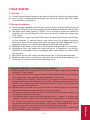
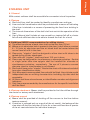
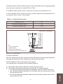
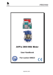
1.2.2 Airflow measuring connections (Figure 1)
A1: to enable measurement of effective reserve, manual reserve and regulator
leakage:
a) For bucket or direct-to-can milking machines connection to be between
the regulator sensing point and the first vacuum tap.
b) For pipeline milking machines connection to be at or near the receiver(s),
upstream of the sanitary trap(s).
c) For recorder milking machines connection to be at or near the sanitary
trap(s) on the milking vacuum line(s)
A2: to enable measurement of leakage into the vacuum and milk systems
a) Connection to be between the vacuum pump(s) and the sanitary trap(s)
or the first vacuum tap.
Note: When not in use, test connections shall not form a trap for liquids.
Connections shall have the same internal diameter as the airline or (48.5±2)
mm, whichever is smaller.
9
Performance
Requirements
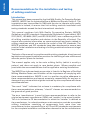
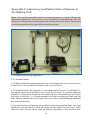
ISO 5707 Milking machine Installations-Construction and Performance
specifies minimum performance and information requirements and certain
dimensional requirements for satisfactory functioning of milking machines
for milking and cleaning.
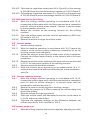
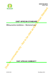
Figure 1: Location of test points in ISO standards (ISO 3918) tees +isolation valves (IV)
1.2.3 Vacuum and airflow measuring connections (Figure 1).
The following measuring points shall be provided for a vacuum or an airflow meter:
a) Vm at or upstream of the measuring point A1.
b) Vr near each regulator sensing point.
c) Vp near each vacuum pump inlet.
d) Pe Connection for measurement of exhaust backpressure of the vacuum
pump outlet.
e) In a pipeline milking machine, Vm can be any point in the milking system,
or upstream of the receiver. In a recorder jar milking machine, Vm can be
in the milking vacuum line or in the nearest convenient recorder jar. In a
bucket milking machine, Vm = Vr and can be combined with the nearest
convenient vacuum tap.
f) All test connections shall be at least five pipe diameters from any bends,
air inlet points or other fittings creating air turbulence.
g) If the regulator sensing point is on a branch, there shall be two measuring
points Vr, one to measure the vacuum drop in the airline upstream of this
branch and the other one to determine the regulator leakage near the
regulator sensing point.
h) Means shall be provided to isolate vacuum pump(s) to measure vacuum
pump capacity.
i) It is necessary that the pulsators can be stopped or disconnected to
measure leakage into the vacuum system and of air used to produce
pulsation.
10
11
Performance
Requirements
1.2.4 Additional IMQCS recommendations for test points and isolation
valves
a) Airflow test points shall consist of a tee-piece complete with a test valve
and “nipple” the valve and “nipple” bores shall not be less than 38mm.
Alternative means for the connection of airflow meters are acceptable
provided that their operation does not necessitate the use of tools.
b) Isolation valves shall be fitted to the main airline near the vacuum pump
on the interceptor side of the test tee-piece and on the sanitary trap
airline between sanitary trap and main airline.
c) Isolation valve bore shall be equal to the bore of the airline in which it is fitted.
d) A separate vacuum pump to operate feeders is preferred but is not
necessary where there is adequate vacuum pump capacity.
e) When a separate vacuum is not provided, means shall be provided to
isolate ancillary equipment, such as vacuum feeder, ACRs, vacuum gates,
water heater controls, teat sprayers, etc.
Safety &
Hygience
SAFETY
AND HYGIENE
12
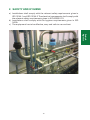
2. SAFETY AND HYGIENE
a) Installations shall comply with the relevant safety requirements given in
ISO 12100-1 and ISO 12100-2. The electrical components shall comply with
the relevant safety requirements given in IEC 60335-2-70.
b) Installations shall comply with the hygiene requirements given in ISO
14159.
c) The equipment has to be effective, easy and safe to use and test.
Safety &
Hygience
13
Materials
MATERIALS
14
3. MATERIALS
15
Materials
a) All components that are subjected to a vacuum shall be designed and
constructed to withstand a minimum vacuum of 90 kPa, without
permanent distortion.
b) Materials that may involve danger if damaged, such as glass, shall be
designed using a safety factor of 5 against external pressure (i.e., 5 x 90 kPa).
c) All materials in contact with milk or cleaning solutions whether used for
rigid components (for example, pipelines or recording jars) or flexible
components (for example, joint rings, teatcup liners), shall be constructed
to withstand the maximum temperature used in the plant as specified in
the instructions. In addition, such materials when used in accordance with
the manufacturer’s recommendations shall not impart taint to the milk.
d) All milk contact surfaces shall be free from engraving or embossing. All
metal milk contact surfaces, except for welded seams, shall have a surface
roughness ® less than or equal to 2.5µm when tested in accordance with
IS EN ISO 4288.
e) Surface roughness (Ra), on welded seams shall not exceed 16µm.
f) Copper or copper alloys shall not be used in any part of the installation
that may come in contact with milk or cleaning and disinfecting fluids
other than water.
g) Materials that come into contact with milk shall be resistant to both milk
fat and cleaning and disinfecting solutions.
User’s
Manual
USER’S
MANUAL
16
4. USER’S MANUAL
4.1 General
a) The User's Manual written in at least one of the country's official
languages shall specify a system of measures that ensure that the
function, safety and hygiene of the milking machine are maintained during
its intended lifetime. This includes instructions for routine servicing and
replacement of individual parts. An indication shall be given as to whether
particular actions should be performed by the user or if other suitably
qualified personnel are needed.
4.2 Installation details
At least the following installation details shall be provided:
a) Mounting dimensions, space requirements and critical building
dimensions.
b) Recommended ambient conditions for the different parts of the milking
machine.
c) Minimum electrical power supply and earthing (grounding) requirements.
d) Minimum water supply and drainage requirements.
e) Nominal working pressure and capacity of a compressed air system.
f) Amount of airflow and vacuum for cleaning.
g) The minimum required airflow use of vacuum-driven ancillary equipment.
17
User’s
Manual
4.3 Instructions for use
At least the following instructions shall be provided:
a) Start up, operating and shut down procedures.
b) The effective reserve, as calculated and as measured.
c) Recommended cleaning and disinfecting procedures, including
temperatures and chemicals, and components requiring manual cleaning.
d) The maximum temperature at which the installation can be cleaned and
disinfected.
e) Definition of any manual intervention, such as manual actuation of valves
or replacement of single use items such as filters, along with the
appropriate time intervals.
f) Procedures necessary to avoid contamination of the milk from cleaning
solutions and from, withheld, abnormal and undesirable milk.
g) The maximum number of units or maximum milkflow per slope of the
milkline.
h) Procedures for introducing animals new to milking installations.
Vacuum
System
VACUUM
SYSTEM
18
5 VACUUM SYSTEM
5.1 General
a) The ultimate goal is to maintain vacuum at teat end within the intended
range. The machine shall be capable of adequate vacuum control and
operators shall use the machine with reasonable care and in accordance
with the user’s manual.
5.2 Vacuum regulation
5.2.1 Vacuum deviation: The working vacuum (Vm), after a defined start-up
period shall be within ± 2 kPa of the nominal.
5.2.2 Regulation sensitivity: Shall not to exceed 1 kPa.
5.2.3 Regulation loss shall not exceed 35 l/min of free air or 10 % of the
manual reserve, whichever is the greater.
Vacuum
System
19
5.2.4 Regulation characteristics and effective reserve
a) Regulation overshoot shall be less than 2 kPa
b) One of the following requirements shall be fulfilled:
1. Vacuum drop and undershoot during cluster fall-off test shall be less
than 2 kPa. This requirement is more appropriate for large milking
systems and where the operators are less careful during attachment
2. The minimum effective reserve given in Table’s 1-4 is more appropriate
for small milking systems (< 8 units)
c) In large milking systems the effective reserve should be sufficient to
maintain working vacuum (Vm) within ± 2 kPa during the course of normal
milking, including teatcup attachment and removal, liner slip or
teatcup/cluster fall, for at least 99 % of the milking time.
5.3 Vacuum pumps
5.3.1 Vacuum Pumps - General
a) The vacuum pump shall have adequate airflow capacity to meet the
requirements for milking and cleaning including air used by all ancillary
equipment operating during milking and cleaning, whether continuously
or intermittently.
b) If more than one vacuum pump is used, it shall be possible to isolate
pump(s) not in use.
5.3.2 Influence of altitude
Vacuum pump capacity decreases with altitude.
5.3.3 Exhaust
a) The exhaust shall not obstruct the passage of the exhaust air by sharp
bends, T-pieces or unsuitably designed silencers.
b) Means shall be provided to minimize oil discharge from oil-lubricated
vacuum pumps into the environment, for example with an oil separator,
collection or recirculation system fitted in the exhaust pipe.
c) Moisture from the exhaust shall be prevented from entering the vacuum
pump, for example by fitting a moisture trap or having the exhaust pipe
with a continuous slope away from the vacuum pump.
d) The exhaust should not discharge into a closed room where foodstuffs are
stored or processed, or where persons or animals are present.
5.3.4 Prevention of reverse flow through vacuum pump
a) Automatic means shall be provided to prevent reverse flow of air from the
exhaust, which may contaminate the milk system.
5.3.5 Location
a) The vacuum pump shall be located so that airline vacuum drop
recommendation (5.6.2) shall be achieved using airlines with reasonable
diameter.
b) The vacuum pump shall be installed so that its capacity, vacuum and
20
where applicable, speed can be easily measured.
c) The vacuum pump(s) should be placed in a well-ventilated and nonfreezing area isolated from the milking parlour and milk room.
5.3.6 Additional IMQCS recommendations for vacuum pumps
a) The farmer shall provide adequate working space around the vacuum
pump to facilitate maintenance and checking.
b) The farmer shall provide adequate drainage in the pump house.
c) The vacuum pump and associated prime mover shall be mounted on a
rigid frame and have guards which provide effective protection to all
accessible moving parts as per Health and Safety Authority guidelines.
The minimum standard of belt guard is outlined in IS EN 294:1994.
d) Safety guards may be opened only if safety is not compromised in any
way.
e) The farmer should provide a standby power source for the vacuum pump.
5.3.7 Additional IMQCS recommendations for exhausts
a) Exhausts shall be fitted and shall be vented to outside the pump room, or
into a container buried underground and vented to the outside.
b) A silencer shall be fitted to the exhaust pipe to reduce the time weighted
average noise level. Additional measures, e.g., doors, ceilings and sumps
may be necessary to achieve acceptable noise levels in the normal
working areas, i.e., dairy, parlour and yard.
c) An oil trap shall be fitted or the exhaust shall be sloped away from the
vacuum pump towards an oil collection container.
d) Exposed exhausts, which may be a burn hazard, shall have a suitable
hazard warning sign.
5.4.1 Regulator leakage shall not exceed 35 l/min of free air or 5 % of the
manual reserve, whichever is greater.
5.4.2 Vacuum regulator shall be mounted in a readily accessible location and
be protected from moisture from the milking machine and installed in a place
and manner in which it does not take in excessive dust.
The regulator should be installed in a place and manner so as to minimize
noise for the operator(s).
5.4.3 Examples of location of sensing point for vacuum regulator.
a) In pipeline and automatic milking machines, either between the interceptor
and the sanitary trap or on the sanitary trap or in the receiver.
21
Vacuum
System
5.4 Vacuum regulator
b) In recorder milking machines, either between the interceptor and the
sanitary trap or on the sanitary trap or in the milking vacuum line.
5.4.4 Additional IMQCS recommendations for vacuum regulators
a) Isolation valves shall be fitted to the regulator air admission valve and
remote sensing point to facilitate testing except where the valve(s)
interferes with the function of the sensing point.
b) Remote sensing point(s) shall be fitted on the cow side of the regulator
air admission valve according to manufacturer’s recommendations.
5.5 Vacuum gauge
5.5.1 Vacuum Gauge - General
a) Shall indicate intervals of 2 kPa or less from 20 kPa to 80 kPa.
b) Gauge error shall not exceed 1 kPa at the working vacuum.
5.5.2 Mounting
a) Gauge is readable by the operator (milker) while milking.
b) More than one vacuum gauge may be needed.
5.6 Airlines
5.6.1 Airlines-general
a) Airlines shall be sloped to a readily accessible drain valve.
b) Airlines shall be self-draining when the vacuum is shut off.
c) Airlines shall have provision for cleaning and inspection.
5.6.2 Airlines-internal diameter and airflow
a) Airlines shall be large enough so vacuum drop does not seriously affect
milking machine function.
b) Vacuum drop between Vm and Vr shall, therefore, not exceed 1 kPa.
c) When Vp > Vm the higher vacuum at Vp increases power consumption
and decreases the vacuum pump capacity. Vp should preferably not
exceed Vm by more than 3 kPa.
5.6.3 Additional IMQCS recommendations for airlines
a) All airlines shall be either galvanized steel, rigid plastic or stainless steel.
b) All airlines shall have reamed ends for the fitting to the tee pieces, bends
and joint fittings and be clamped and fixed to prevent sagging. Rigid
plastic or stainless steel piping shall have welded, socketed or sealed
couplers on joints, bends and tee pieces, be clamped and fixed to prevent
sagging and be sufficiently protected to avoid accidental damage by cows
or operators.
c) Bends shall be swept with a minimum centerline radius of 1.5 times the diameter.
Pulsation airlines should not be more than 2.1m above the cow standing.
22
d) Pulsation airlines shall have a tap or bung fitted at the ends to facilitate
adequate washing. Pulsator and relay entries shall be into the top or side
of pulsation airlines.
e) An ancillary airline should be of rigid material and shall be sloped to a
drain valve to facilitate drainage and shall have a tap or bung fitted at the
end to facilitate adequate washing.
5.7 Interceptor
a) Shall be fitted near the vacuum pump, between the vacuum pump and
the regulator.
b) There shall not be any intermediate connections into the airline between
the interceptor and the vacuum pump, except as required for test
purposes or for the connection of a safety valve.
c) A safety valve may be fitted to protect the pump from effects of high
vacuum caused by the activation of any vacuum shut-off valve in the
interceptor.
d) Means shall be provided to prevent liquids trapped in the interceptor from
entering the vacuum pump.
e) Interceptor(s) shall have automatic drainage facilities.
f) It shall be possible to inspect and clean the inside of the interceptor(s).
g) The effective volume of the interceptor(s) shall be given in the user's
manual and should be adequate to facilitate washing of the airlines (as
determined by airline sizes).
5.9 Leakage into the vacuum system
a) Leakage into the vacuum system shall not exceed 5 % of the vacuum
pump capacity at the working vacuum and for capacity-controlled vacuum
pumps at the pump's maximum capacity.
5.10. Additional IMQCS recommendation for sanitary trap(s)
a) The sanitary trap shall be fitted with a automatic cut-off valve.
23
Vacuum
System
5.8 Sanitary trap
a) A sanitary trap shall be fitted between the milk system and the vacuum
system in pipeline and recorder milking machines.
b) The sanitary trap shall be located between the receiver vessel and the
vacuum system, except where the vacuum and pulsation systems form
part of the routine circulation cleaning and disinfection system.
c) The sanitary trap shall have provision for drainage and means to minimize
liquid entry into the vacuum system.
d) Effective volume of the sanitary trap shall be stated in the User's Manual.
e) It shall be possible for the operator to detect the presence of milk and/or
cleaning solutions in the sanitary trap when the machine is running.
f) It is an advantage if the sanitary trap is visible to the operator during milking.
g) Where there is no provision for circulation cleaning of the sanitary trap(s),
the receiver(s) and the receiver airline, this line shall be designed to drain
towards the sanitary trap.
Pulsation
System
PULSATION
SYSTEMS
24
6. PULSATION SYSTEMS
6.1 Design data that shall be included in the User's Manual:
a) The pulsation rate and pulsator ratio at a nominal vacuum and specified
temperature.
b) The temperature range over which the pulsation rate will stay within ± 5%
of the nominal pulsation rate.
c) The temperature range over which the pulsators can be operated and the
variation of pulsation rate within this range.
d) Typical pulsation chamber vacuum records for a defined milking unit.
d) Total air use with a defined milking unit connected under specified
operating conditions.
e) Deliberate variations in pulsation rate and pulsator ratio, e.g., in
conjunction with stimulation and changes in milkflow.
6.2 Pulsator airline
a) Vacuum drop between working vacuum (Vm) and maximum pulsation
chamber vacuum shall be no more than 2 kPa.
25
Pulsation
System
6.3 Pulsation rate, pulsator ratio and pulsation chamber vacuum phases
a) The pulsation rate shall not deviate more than ± 5 % from intended values
given in the User's Manual. Note: Pulsation rate is typically between 50
cycles/min and 65 cycles/min for cows.
b) The pulsator ratio shall not differ more than ± 5 units of percentage from
the values given in the User's Manual.
c) The pulsator ratios shall not vary from each other by more than 5 units of
percentage.
d) Limping shall not be more than 5 units of percentage except where the
milking unit is designed to provide different ratios between the fore- and
hindquarters.
e) Phase b shall be not less than 30 % of a pulsation cycle and phase d shall
be not less than 150ms.
f) Vacuum drop during Phase b shall not be more than 4 kPa below
maximum pulsation chamber vacuum.
g) Vacuum during Phase d shall not be more than 4 kPa.
6.4 Additional IMQCS recommendations for pulsation systems
a) Simultaneous or alternate pulsation patterns are acceptable.
b) Pulsation relays shall be de-synchronized to reduce the amplitude of
vacuum fluctuations within the pulsation airlines.
c) Long pulse tubes shall have a minimum bore of 9.5 mm for simultaneous
pulsation or 7 mm for alternate pulsation.
d) Pulsation relays and pulsators should be capable of being washed
through the long pulse tubes.
e) A breather airline shall be fitted. Clean air may be sourced inside or
outside the milking parlour. If clean air is sourced inside the milking
parlour a filter shall be fitted to the manufacturer’s specification. If clean
air is sourced outside the milking parlour the breather airline shall have
end pieces angled downwards and meshed.
f) The fitting of breather airlines shall not alter the pulsation performance.
g) The pulsation air consumption should typically be within the range of 2535 litres per minute per unit and shall not exceed 45 litres per minute per
unit.
h) The pulsation “a phase” shall be less than 22%.
26
Pulsation
System
27
Milk System
MILK
SYSTEM
28
7 MILK SYSTEM
7.1 General
a) It shall be possible to inspect the inside of the milk system for cleanliness.
b) Any air that is deliberately admitted into the milk system shall be stated
in installation instructions.
7.2 Design of milklines
a) Vacuum drop between the receiver and any point in the milkline shall not
exceed 2 kPa with all units operating at the designed milkflow and airflow.
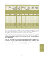
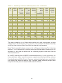
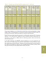
b) Diameter and slope shown in Table 1 for a mid-level plant are based on
milkflow per cow of 5kg/min, 100 l/min transient airflow per slope and
1.5% slope.
c) If installed in a loop, each end shall have a separate full-bore connection
to the receiver. If several loops, two ends may be grouped together
directly in front of the receiver to form a single line with adequate crosssectional area for the combined designed milkflow and airflow.
d) Milklines shall have a continuous fall towards the receiver for drainage.
e) Equipment that can cause an obstruction or a reduction in vacuum,
milkflow or drainage, such as enlargements, restrictions or filters, shall
not be used.
f) Minimum centre-line radius for bends shall be 1.5 times the diameter.
g) Milklines should be installed to minimize the milk lift and preferably no
more than 2 m above the animal standing level.
29
Milk System
7.3 Additional IMQCS recommendations for milklines
a) Milklines and milk diversion lines shall have a slope towards the receiver
vessel of 1% or greater.
b) The highest point of the long milk tube should ideally not be greater than
2.1m above the cow standing and preferably 1.7m or less.
c) All saddle type “nipples” shall have a protrusion into the milkline to
prevent poor alignment with the hole in the milkline due to rotation of the
saddle. This protrusion shall not protrude more than 0.8 mm past the
inner surface of the milkline.
d) Rubber joints or bends may not be used in milklines; plastic or stainless
steel unionized cone seal connections are acceptable.
e) All bends in milkines shall be stainless steel with a centreline radius not
less than 1.5 times the diameter.
f) All milklines shall have a stainless steel end entry “nipple” or a side entry
“nipple” no more than 30 mm from the blank capped end. In either case,
the end of the milkline should be capable of being inspected, i.e., a
removable end piece on the milkline. This does not preclude this use of
valving systems at the end of milklines to facilitate washing.
g) Where “nipples” are welded on to a milkline, the inside of the weld shall
be flared and suitably dressed.
h) The stainless steel shall be cut at 90° at all milking joints; this necessitates
using mechanical cutting equipment.
i) For mid-level parlours curved (swan neck) entries are preferred to straight
entries for milklines when swing over arms, milk meters and/or ACRs are
not used.
j) Stainless steel of 0.9mm (gauge 20) wall thickness or greater and quality
“Standard 304 Dairy Tubing” shall be used in milklines.
k) Provision shall be made for the inspection of the inside of milklines.
l) The vertically dropping section (into the receiver) of the milkline shall be
less than 300 mm.
m) Air injection or other appropriate washing systems shall be used with
milkline greater than 48.5 mm in bore.
n) The highest point of each long milk tube (at each unit) before entering
milklines and milk diversion lines shall be equal except where valving
systems are used to control the flow of wash solution between the lines.
o) Milk entries shall be in the top third of the milk pipeline in pipeline milking
plants.
7.4 Additional IMQCS recommendations for washlines in milkline plants
a) Washlines shall be of adequate bore as shown in Tables 1-5, as
appropriate.
b) All saddle type “nipples” shall have a protrusion into the washline to
prevent poor alignment with the hole in the washline due to rotation of
the saddle. This protrusion shall not protrude more than 0.8 mm past the
inner surface of the washline.
c) Rubber joints or bends may not be used in washlines; plastic or stainless
steel unionised cone seal connections are acceptable. All bends in
washlines should be stainless steel, with a centreline radius not less than
1.5 times the diameter.
d) All washlines shall have a stainless steel end entry “nipple” or a side entry
“nipple” no more than 30 mm from the blank capped end. In either case,
the end of the washline should be capable of being inspected, i.e., a
removable end piece on the washline. This does not preclude the use of
valving systems at the end of washlines to facilitate washing.
e) The stainless steel shall be cut at 90° at all washline joints; this
necessitates using mechanical cutting equipment.
f) Washline entries shall be into the top or top-third of the pipeline.
g) Stainless steel of 0.9mm (gauge 20) wall thickness or greater and quality
“Standard 304 Dairy tubing” shall be used in washlines. This does not
preclude the use of inspection windows in washlines.
h) When closed circulation is required for plants with diaphragm pumps, a
method for the safe connection of the suck-up tube to the return tubes
shall be provided.
i) A suitable mechanism should be installed for the safe uptake and return
of detergent solutions to avoid accidental splashing of chemicals.
30
7.5 Additional IMQCS recommendations for milk transfer lines in recording
jar plants
a) All saddle type “nipples” shall have a protrusion into the milk transfer
lines to prevent poor alignment with the hole in the milk transfer line due
to rotation of the saddle. This protrusion shall not protrude more than 0.8
mm past the inner surface of the milk transfer line.
b) Rubber joints or bends may not be used in milk transfer lines; plastic or
stainless steel unionized cone seal connections are acceptable. All bends
in milk transfer lines should be stainless steel with a centreline radius not
less than 1.5 times the diameter.
c) All milk transfer lines shall have a stainless steel end entry “nipple” or a
side entry “nipple” no more than 30 from the blank capped end. In either
case, the end of the milk transfer line should be capable of being
inspected, i.e. a removable end piece on the milk transfer line. This does
not preclude the use of valving systems at the end of milk transfer lines
to facilitate washing.
d) The stainless steel shall be cut at 90° at all milk transfer line joints; this
necessitates using mechanical cutting equipment.
e) Stainless steel of 0.9mm (gauge 20) wall thickness or greater and quality
“Standard 304 Dairy Tubing” shall be used in milk transfer lines.
f) Provision shall be made for the inspection of the inside of milk transfer
lines.
g) The milk transfer line should not be higher than two thirds of the height
of the recording jar when it is intended to “milk though the jars”.
h) Milk transfer line slopes shall be 1% or greater.
31
Milk System
7.6 Additional IMQCS recommendations for milking vacuum/wash lines in
recording jar plants
a) All saddle type “nipples” shall have a protrusion into the milking
vacuum/wash lines to prevent poor alignment with the hole in the milking
vacuum/wash line due to rotation of the saddle. This protrusion shall not
protrude more than 0.8 mm past the inner surface of milking
vacuum/wash line.
b) Rubber joints or bends may not be used in milking vacuum/wash lines;
plastic or stainless steel unionised cone seal connections are acceptable.
All bends in milking vacuum/wash lines should be stainless steel with a
centreline radius not less than 1.5 times the diameter.
c) All milking vacuum/wash lines shall have a stainless steel end entry
“nipple” or a side entry “nipple” no more than 30 mm from the blank
capped end. In either case, the end of the milking vacuum/wash line
should be capable of being inspected, i.e., a removable end piece on the
milking vacuum/wash line. This does not preclude the use of valving
systems at the end of milking vacuum/wash lines to facilitate washing.
d) Where “nipples” are welded on to a milk transfer line, the inside of the
weld shall be flared and suitably dressed.
e) Three-way valves shall be full-bore stainless steel or other suitable food
grade material.
f) Three-way or equivalent valves shall be easily accessible.
g) The vacuum supply to the milking vacuum/wash line may come from the
sanitary trap, receiver or receiver airlines.
h) The milking vacuum/wash line shall slope towards the 3-way valve (or
equivalent) for drainage purposes.
7.7 Additional IMQCS recommendations for milk recording equipment
a) The highest point of the long milk tube should ideally not be greater than
2.1m above the cow standing and preferably 1.7m or less. .
b) Recording jars shall be rigidly fixed in a vertical position consistent with
accurate measurement of milk volume.
c) Recording jars shall be graduated to allow milk recording in units of 0.5
kg from 2 kg upwards.
d) Recording jars shall be fitted with a spreader device to distribute the wash
over the jar surface without excessively restricting airflow.
e) The milking vacuum/wash line “nipple” on the recording jar shall have a
minimum bore of 16mm.
f) The milking vacuum/wash tube connected to recording jars shall have a
minimum bore of 15mm.
g) A facility shall be provided for agitating the milk, removing a sample and
draining the recording jar contents.
h) The exit “nipple” bore at the base of the recording jar and the transfer
tubes bore shall be at least 18mm.
i) All milk meters shall be International Committee for Animal Recording
(ICAR) approved.
7.8 Air leakage: Air leakage shall not exceed 10 l/min, plus 2 l/min for each
milking unit.
7.9 Drainage: Provisions shall be made for complete drainage of all parts of
the milk system.
7.10 Milk inlets: Shall be fitted to the upper half of a pipeline.
7.11 Diversion of milk:
a) There shall be provisions to ensure that withheld, abnormal or undesirable
milk cannot be mixed with normal milk.
7.12 Receiver
a) Receiver shall have sufficient volume to accommodate slugs of liquid
which may be formed during milking and cleaning and the volume shall
be stated in the installation instructions.
b) Inlet(s) should be shaped to limit formation of foam during milking.
32
7.13 Releaser
7.13.1 General
a) Releaser shall be adequate to deal with the maximum flow at which milk,
cleaning and disinfecting fluids flow through the system.
b) The releaser milk pump’s discharge flow at 50 kPa working vacuum and
typical discharge pressures shall be stated in the instructions for
installation.
c) There shall be no air leaks in the releaser or between the receiver and the
releaser.
d) Back-flow of milk from the releaser shall be prevented.
7.13.2 Control of releaser milk pumps
a) Milk pump operation shall be controlled by the quantity of milk in the
receiver so that flooding of the receiver or mixing of air and milk is
avoided.
7.14 Delivery line
a) Means shall be provided at every low point to permit drainage of the
delivery line, filters and any in-line cooling equipment.
b) If compressed air is used to purge milk, this air shall be free from
contaminants.
c) The method of air injection should prevent unnecessary formation of free
fatty acids.
d) Means (preferably automatic) shall be provided to stop flow of coolant in
in-line cooling equipment during the wash cycle.
e) If a restriction needs to be fitted in the delivery line to reduce milkflow to
that suitable for an in-line cooler or where an in-line cooler restricts flow
below that needed for cleaning and disinfection, means shall be provided
to open or bypass the restriction during the washing cycle.
Milk System
33
Milking Unit
MILKING
UNIT
34
Milking Unit
8 MILKING UNIT
8.1 General
Milk contact surfaces shall be accessible for convenient visual inspection.
8.2 Teatcup
a) Shell and liner shall be marked to identify manufacturer and type.
b) Liner and shell combination shall be provided with a means of indicating
if the liner is twisted or a means of preventing the liner from twisting in
the shell.
c) The internal dimensions of the shell shall not restrict the operation of the
liner.
d) User's Manual shall include air use caused by a teatcup fall-off or cluster
fall-off and sufficient data to be able to choose the liner for a herd.
8.3 Additional IMQCS recommendations for milking clusters
a) The effective volume of each claw shall not be less than 150 ml.
b) Where an air admission hole is present in the claw, it shall allow a constant
6 – 12 l/min air admission and the air bleed shall be located above the
normal level of milk in the claw.
c) Claw entry “nipples” shall be designed to allow short milk tubes to be
sealed during cluster attachment.
d) Claw milk exit “nipples” shall be at least 12.5 mm in bore.
e) Claws may be designed for simultaneous or alternate pulsation. Double
or single pulse tube claw spigots shall be installed for alternate or
simultaneous pulsation, respectively. The use of Y pieces to convert
alternate claws to simultaneous is not allowed.
f) Shells shall have pulse “nipples” fitted at the short milk tube end and shall
have clear identification marks.
g) Only Moorepark recommended liners should be fitted. Liners/clusters with
independent data on milking characteristics including slip data shall be
acceptable.
h) All liners shall have a brand name, an identification number and alignment
indicators.
i) Only liners recommended by the manufacturer for the specific installation
shall be fitted.
8.4 Teatcup attachment: Means shall be provided to limit the airflow through
the cluster or teatcup until attachment.
8.5 Teatcup removal
a) Means shall be provided of shutting off the vacuum to the liner before
teatcup removal.
b) If vacuum is reduced only as a result of the air vent(s), the leakage of the
claw shut-off shall be less than 2 l/min for a claw and less than a quarter
of the air vent admission for individual teatcups.
35
c) Teatcup removal shall be initiated by one of the following:
i) If milkflow is not present after a specified time.
ii) When the milkflow has ceased or has gone below a specified flow.
iii)When a specified total machine-on time has elapsed.
iv)By human intervention.
d) This initiation together with the limits shall be described in the User's
Manual.
8.6 Vacuum shut-off: It shall be possible to shut off vacuum to the liner when
not milking.
8.7 Air vent and leakage
a) Total air admission per cluster shall be at least 4 l/min and shall not exceed
12 l/min for cows at the nominal working vacuum.
b) Air vent(s) shall be made of a rigid material.
c) Where there is a risk of slugs in the short milk tube at designed milkflow,
means shall be applied to avoid them.
d) The above quantitative requirements do not apply to quarter milking, or
clusters with deliberate cyclic air admission or other specific designs. In
such cases, the total air admission per cluster or teat cup shall be stated
in the User's Manual.
e) Air vents necessary for proper operation of milk meters, automatic teatcup
valves or other devices may add air admission. This air use and location
shall be stated in the User's Manual.
f) Leakage into each cluster assembly with the liners and air vent(s) plugged
and the vacuum shut-off valve opened shall not exceed 2 l/min.
g) Air vents should be positioned to avoid unnecessary turbulence in the
milk.
8.8 Vacuum in the milking unit
a) User's Manual shall state, for specified milkflows:
i) The desired average liner vacuum and/or the desired average liner
vacuum during phase b and phase d of the pulsation chamber vacuum
record.
ii) The corresponding nominal vacuum in the milkline based on the
average vacuum drop.
Note: Both research and field experience indicate that a mean liner vacuum
within the range 32 kPa - 42 kPa during the peak flow period of milking
for cows ensures that most cows will be milked quickly, gently and
completely.
b) The effect on the milking vacuum conditions shall be stated in the User's
Manual. For non-standard devices not originally fitted to a milking unit
between the cluster and the milkline or milking vacuum line.
36
Milking Unit
8.9 Milk recording equipment
8.9.1 General: Milk recording equipment shall comply with the requirements
given in 8.10. The requirements for official yield recording are stated by the
International Committee for Animal Recording (ICAR).
8.9.2 Recorder jars shall comply with the following requirements:
a) Effective volume shall be stated in the User's Manual.
b) Internal diameter of the outlet shall be not less than 18 mm for cows.
c) Connections should be placed to minimize the risk of carry-over of milk or
froth into the vacuum system.
d) Recorder jars should have means of ensuring even distribution of cleaning
and disinfecting fluids over the internal surface during washing without
adversely affecting the vacuum in the recorder jar during milking.
8.10 Attachments to the milking unit
a) Devices, including additional necessary connecting tubes, fitted between
the cluster or teatcup and the milkline or milking vacuum line, shall not
cause any additional vacuum drop greater than 5 kPa at a milkflow of 5
kg/min for cows compared with the same milking unit without those
devices.
8.11 Long milk tubes
a) Means shall be provided to minimise the risk of flattening.
b) Where milk is lifted by means of airflow, the maximum internal diameter
of the long milk tube shall be:
i) 16 mm for cows
ii) Where long milk tubes are attached to single teatcups it is advisable to
use tubes with a smaller diameter
c) The length and the internal diameter of long milk tubes shall be specified
in the user's manual with the airflow at the end of the long milk tube
measured in accordance with ISO 6690.
d) The long milk tubes shall be short as is practicable.
37
Cleaning
CLEANING
38
9 CLEANING
9.1 Additional IMQCS recommendations for milk pumps and milk filters
a)
b)
c)
d)
e)
Milk pumps shall have adequate output for milking and washing.
Drain valves shall be fitted to allow routine drainage of milk pumps.
All milk pumps shall be operated intermittently by milk level or weight.
An inline milk filter shall be fitted in all milking installations.
Where a plate cooler is fitted, the milk filter shall be fitted between the
milk pump and the plate cooler.
f) The milk filter assembly shall be adequately sized to suit to the flow rate
of the milk pump.
g) Only stainless steel or other food grade material shall be used in milk filter
assemblies.
h) Inline filters shall be mounted vertically with the drain/cap at the base.
39
Cleaning
a) The cleaning system shall be designed and installed so that cleaning and
disinfecting solutions cannot enter the milk.
b) Methods of verifying that the cleaning system is operating properly, and
any components that shall be manually disassembled or hand cleaned
shall be specified in the User's Manual.
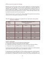
The success of a circulation cleaning system depends on: design and
installation ensuring adequate circulation volume, velocity and contact
time of cleaning solutions; temperature and concentration appropriate to
the type of cleaning and sanitizing solutions used.
c) A velocity range of 7 m/s to 10 m/s is preferred for the cleaning of pipelines
containing liquid-slugs. It is expected that any cleaning procedure will:
i) Leave milk contact surfaces visibly free from milk residues and other
deposits.
ii) Leave surfaces free from undesirable residues of cleaning and
disinfecting chemicals.
iii)Reduce the count of viable bacteria to an acceptable level on milk
contact surfaces.
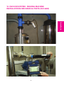
Vacuum System
VACUUM SYSTEM
- MILKING MACHINE
INSTALLATIONS
- MECHANICAL TESTS
(ISO 6690)
40
10. VACUUM SYSTEM - MILKING MACHINE
INSTALLATIONS-MECHANICAL TESTS (ISO 6690)
Vacuum System
41
10.1 General requirements and preparation.
10.1.1 General
a) To keep the plant in good condition, periodic checking is recommended.
If the effective reserve has not changed it is not necessary to carry out
further tests on the vacuum regulator or pump capacity tests.
10.1.2 Preparation before testing
a) Start the vacuum pump and put the milking machine into the milking
position with all milking units connected. Teatcup plugs shall be in the
milking position. All vacuum-operated equipment associated with the
installation shall be connected including those not operating during
milking. Allow the vacuum pump to run for at least 15 minutes before
taking any measurements.
10.2 Vacuum regulation
10.2.1 Test of vacuum regulation deviation
With the milking machine running in accordance with 10.1.2, record the
working vacuum at the receiver and compare it with the nominal vacuum.
10.2.2 Regulation sensitivity
10.2.2.1 With the milking machine operating in accordance with 10.1.2 with
liners plugged, connect a vacuum meter to the connection point
Vm.
10.2.2.2 Record the vacuum as the working vacuum for the milking
machine.
10.2.2.3 Shut off all milking units and record the vacuum. The milking
machine shall then be in the same state as during milking but with
no milking unit in operation.
10.2.2.4 Calculate the regulation sensitivity as the difference between the
vacuum measured with no milking units in operation (10.2.2.3) and
that with all units operating (10.2.2.2).
10.2.3 Regulation loss
10.2.3.1 With the milking machine operating in accordance with 10.1.2 with
liners plugged, connect the airflow meter with a full-bore
connection to connection point A1 with the airflow meter closed.
Connect a vacuum meter to the connection point Vm.
10.2.3.2 Record the vacuum as the working vacuum for the milking machine.
10.2.3.3 Open the airflow meter until the vacuum decreases by 2kPa and
record the airflow.
10.2.3.4 Stop any airflow through regulators that admit air.
10.2.3.5 Decrease the vacuum by opening the airflow meter to drop the
vacuum 2 kPa.
10.2.3.6 Calculate the regulation loss as the difference between the airflows
recorded in 10.2.3.5 and 10.2.3.3
42
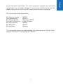
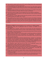
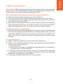
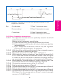
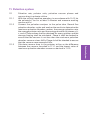
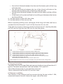
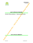
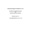
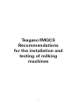
Key
A undershoot
1 Phase 1: no teatcup open
B vacuum drop
2 Phase 2: teatcup(s) are open
C overshoot
3 Phase 3: teatcup(s) open
4 Phase 4: teatcup(s) are closed
10.2.4 Tests of regulation characteristics
10.2.4.1 The regulation characteristics are preferably tested in the fall-off
and attachment tests.
Milking unit with automatic shut-off valve:
a) Use one cluster with shut-off valve enabled (fall-off test)
b) Use one teatcup, with the shut-off valve in attachment position
(attachment test).
c) Figure 2-Regulation undershoot, vacuum drop and regulation
overshoot for rapid changes in air admission
10.2.4.2 With the milking machine operating with liners plugged connect a
vacuum recorder to measuring point Vm.
10.2.4.3 Record the vacuum for 5 s to 15 s: Phase 1 of Figure 2.
10.2.4.4 While recording, open one teatcup or one cluster and record for 5
s to 15 s after the vacuum has stabilized: Phases 2 and 3 of Figure
2. If there are 32 or more clusters or teatcups (for quarter milking)
are connected, open one cluster or teatcup per every 32 clusters.
10.2.4.5 While recording, close the teatcup or cluster and record for 5 s to
15 s after the vacuum has stabilised: Phase 4 of Figure 2.
10.2.4.6 Calculate the average vacuum during 5 s of Phase 1.
10.2.4.7 Find the minimum vacuum of Phase 2.
10.2.4.8 Calculate the average vacuum during 5 s of the stable part of Phase 3.
10.2.4.9 Find the maximum vacuum of Phase 4.
10.2.4.10 Calculate the average vacuum during 5 s of the stable part of Phase 4.
10.2.4.11 Calculate the fall-off vacuum drop or the attachment vacuum drop
(B in Figure 2) as the average vacuum (Phase 1) minus the average
vacuum in 10.2.4.8 (Phase 3).
43
Vacuum System
Figure 2: Regulation undershoot, vacuum drop and regulation overshoot for rapid
changes in air admission
10.2.4.12 Calculate the regulation undershoot (A in Figure 2) as the average
in 10.2.4.8 (Phase 3) minus the minimum vacuum in 10.2.4.7 (Phase 2).
10.2.4.13 Calculate the regulation overshoot (C in Figure 2) as the maximum
in 10.2.4.9 (Phase 4) minus the average vacuum in 10.2.4.10 (Phase 4).
10.2.5 Effective reserve for milking
10.2.5.1 With the milking machine operating in accordance with 10.1.2,
connect the airflow meter with a full-bore connection to connection
point A1 with the airflow meter closed. Connect a vacuum meter
to the connection point Vm.
10.2.5.2 Record the vacuum as the working vacuum for the milking
machine.
10.2.5.3 Open the airflow meter until the vacuum decreases by 2kPa from
the value in 10.2.5.2.
10.2.5.4 Record the airflow through the airflow meter.
10.3 Vacuum pumps
10.3.1
Vacuum pump capacity
10.3.1.1 With the machine operating in accordance with 10.1.2 record the
vacuum at the vacuum pump measuring connection Vp as the
working vacuum from the pump.
10.3.1.2 Isolate the vacuum pump from all other parts of the installation.
Connect the airflow meter directly to the vacuum with a full-bore
connection.
10.3.1.3 Record the airflow meter reading at the same vacuum as recorded
in 10.3.1.1as the pump capacity at the working vacuum.
10.3.2
Vacuum pump exhaust back pressure.
10.3.2 .1 With the vacuum pump operating in accordance with 10.3.1.1,
measure and record the exhaust back pressure at the connection
point Pe.
10.4 Vacuum regulator leakage
10.4.1
With the milking machine operating in accordance with 10.1.2,
connect the airflow meter with a full-bore connection to connection
point A1 with no airflow through it. A vacuum meter shall be
connected to connection point Vr.
10.4.2
Record the vacuum as the regulator working vacuum.
10.4.3
Decrease the vacuum by 2 kPa by opening the airflow meter and
record the airflow.
10.4.4
Stop the airflow through regulator(s).
10.4.5
Open the airflow meter and decrease the vacuum to the same as
in 10.4.3 and record the airflow.
10.4.6
Calculate the regulator leakage as the difference between the
airflow recorded in 10.4.5 and that in 10.4.3.
10.5 Vacuum gauge error
10.5.1
With the milking machine and vacuum regulator operating, but with
44
10.5.2
no milking unit operating, and the test vacuum meter connected to
connection point Vr, record the values on the vacuum gauge of the
plant and the test vacuum meter.
Record the difference between these two values as the error of the
gauge.
10.7 Leakage in vacuum system
10.7.1
With the milking machine operating in accordance with 10.1.2 with
all units plugged connect the airflow meter with a full-bore
connection to point A2 with no airflow through it. Connect a
vacuum meter to point Vr or Vp.
10.7.2
Record the vacuum as the regulator or vacuum pump working
vacuum.
10.7.3
Isolate the vacuum system from the milk system. Stop the airflow
through the vacuum regulator.
10.7.4
Adjust the airflow meter until the vacuum is the same as that
recorded in 10.7.2. Record the working vacuum at the vacuum pump
connection point Vp.
10.7.5
Isolate the vacuum pump from the rest of the vacuum system.
Connect the airflow meter directly to vacuum pump with a full-bore
connection.
10.7.6
Open the airflow meter until the working vacuum at the vacuum
pump becomes the same as recorded in 10.7.4 Calculate the
vacuum system leakage as the difference between the airflow
recorded with the vacuum system disconnected (10.7.6) and the
airflow with the vacuum system connected (10.7.4).
45
Vacuum System
10.6 Vacuum drop in airline
10.6.1
With the milking machine operating in accordance with 10.1.2,
connect the airflow meter with a full-bore connection to point A1
with no airflow through it. A vacuum meter shall be connected to
point Vm. Record the vacuum as the working vacuum for the
milking machine.
10.6.2
Open the airflow meter until the vacuum at Vm decreases by 2kPa
and record the working vacuum.
10.6.3
Move the vacuum meter to regulator connection point Vr and
record the working vacuum.
10.6.4
Calculate the vacuum drop between Vm and Vr as the difference
between the vacuum recorded in 10.6.2 at Vm, and that recorded
in 10.6.3 at Vr, with the same airflow in both cases.
10.6.5
Move the vacuum meter to vacuum pump connection point Vp and
record the working vacuum.
10.6.6
Calculate the vacuum drop between Vm and Vp as the difference
between the vacuum recorded in 10.6.2 at Vm, and that recorded
in 10.6.5, at Vp, with the same airflow in both cases.
Pulsation System
PULSATION
SYSTEM
46
11. Pulsation system
11.1
11.1.1
11.1.2
11.1.3
47
Pulsation System
Pulsation rate, pulsator ratio, pulsation vacuum phases and
vacuum drop in pulsator airline.
With the milking machine operating in accordance with 10.1.2 let
the pulsator(s) run for at least 3 minutes and measure working
vacuum at Vm.
Connect the pulsation analyzer to the pulse tube. Record five
pulsation chamber cycles and analyze the results to determine the
maximum pulsation chamber vacuum, the average pulsation rate,
the average pulsator ratio and the average duration of phases a, b,
c, and d. These values shall be obtained for every pulsator and the
average limping shall be calculated. Phase b shall be checked to
ensure that the vacuum is not less than the maximum pulsation
chamber vacuum minus 4 kPa. Phase d shall be checked to ensure
that the vacuum never exceeds 4 kPa.
Calculate vacuum drop in the pulsator airline as the difference
between the vacuum recorded in 11.1.1 and the lowest value of
maximum pulsation chamber vacuum as derived in 11.1.2.
Milk System
MILKING
SYSTEM
48
12. MILK SYSTEM
12.2 Milk system leakage
12.2.1 With the milking machine operating in accordance with 10.1 2,
connect the airflow meter with a full-bore connection to connection
point A2 with no airflow through it. Connect vacuum meter to
connection point Vr or Vp.
12.2.2 Record the vacuum as the regulator or vacuum pump working vacuum.
12.2.3 Stop the airflow through the vacuum regulator. Stop or isolate the
pulsators and all vacuum operated equipment. Plug all air
admissions.
12.2.4 Adjust the airflow meter until the vacuum is the same as the vacuum
recorded in 12.2.2. Record the airflow.
12.2.5 Isolate the milk system.
12.2.6 Open the airflow meter until the vacuum becomes the same as
recorded in 12.2.2.
12.2.7 Calculate the milk system leakage as the difference between the
airflows 12.2.6 and 12.2.4.
49
Milk System
12.1 Slope of milkline
12.1.1 Calculate the minimum slope of each branch between the receiver
and the most distant milk inlet from the receiver. The minimum slope
shall be given for a 5 m section of each branch. Find the average
slope over a series of 5m distances along the milkline, and choose
the lowest value to present the minimum slope of the branch. Slope
shall be given in mm/m with a positive value meaning falling towards
the receiver.
Milking Unit
MILKING
UNIT
50
13. MILKING UNIT
13.1
13.1.1
13.1.2
13.1.3
Teatcup or cluster fall-off air inlet.
With the milking machine operating without the vacuum regulator,
and airflow meter connected to point A1 with a full-bore connection
and a vacuum meter connected to point Vm, adjust the airflow meter
until the vacuum is 50 kPa.
Open one teatcup or one cluster with the shut-off valve open and
adjust the airflow meter until the vacuum is the same as 13.1.1.
The cluster or teatcup consumption is the difference in airflow.
13.2 Leakage through shut-off valves of milking units
13.2.1 Connect a flowmeter between the long milk tube and the cluster or
teatcup under test.
13.2.2 With the shut-off valve in take-off position, measure the airflow and
record this value as the leakage through the shut-off valve.
13.3 Air vent and leakage into teatcup or cluster
13.3.1 Connect a flowmeter between the long milk tube and the claw or
teatcup under test.
13.3.2 Connect the flowmeter to the vacuum system (milkline or airline) and
record the working vacuum for the milking machine.
13.3.3 Plug the teatcup(s) and open any cluster shut-off valve.
13.3.4 Record the airflow through the flowmeter as the total air admission.
13.3.5 Close the air vent and record the airflow through the flowmeter as
the air leakage.
13.3.6 Calculate the difference between the airflows as the air vent
admission.
13.5 Measurement of the vacuum drop from accessories attached in the long
milk tube
13.5.1 The effect of milk meters or accessories inserted in the long milk tube
shall be registered by measuring the average liner vacuum in a
specified milking unit both with and without the accessories
connected, and by comparing the results. Details of the
measurement procedure are given in Appendix C.
51
Milking Unit
13.4 Measuring the vacuum in the cluster (Appendix C)
13.4.1 Record the vacuum in the milkline, at the teat end and in the
pulsation chamber with the specified liquid flows equally divided
between all teatcups of the cluster.
13.4.2 Calculate the working vacuum in the milkline, the average teat end
vacuum and, during Phases b and d, the average teat end vacuum.
13.6 Airflow at the end of the long milk tube
13.6.1 Check the length and internal diameter of the long milk tube.
13.6.2 With the milking machine operating with all units plugged connect a
vacuum meter to the connection point Vm. Record the vacuum as
the working vacuum for the milking machine.
13.6.3 Connect the airflow meter and a vacuum meter to the end of the long
milk tube instead of the claw or teatcup.
13.6.4 Record the vacuum at the end of the long milk tube with the airflow
meter closed and with an air inlet of 10 l/min.
13.6.5 Open the airflow meter until the vacuum at the end of the long milk
tube is 5 kPa lower than the vacuum measured above.
13.6.6 Record the reading of the airflow meter as the airflow at the end of
the long milk tube.
52
TABLES
Tables
53
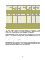
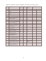
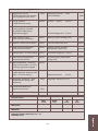
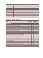
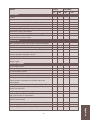
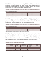
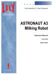
Table 1: Midi-level milkline plants with 2 stalls/unit
No. Milkline
Units
Bore
(mm)
4
6
8
10
12
14
16
18
20
22
24
26
28
30
32
34
36
38
40
48.5
60
60
60
73
73
73
73
73
73
73
98
98
98
98
98
98
98
98
Effective
Reserve
for
Washing
(l/min)
Effective
Reserve
for
Milking
(l/min)
Sanitary
Trap E.
Volume
(l)
Wash
Line
Bore
(mm)
Minimum
443
678
678
678
1004
1004
1004
1004
1004
1004
1004
1809
1809
1809
1809
1809
1809
1809
1809
320
380
440
500
520
540
560
580
600
620
640
660
680
700
720
740
760
780
800
10
10
10
10
10
20
20
20
20
20
20
20
20
20
20
20
20
20
20
38
38
38
48.5
48.5
48.5
48.5
48.5
48.5
48.5
60
60
60
60
60
60
60
60
60
Main Estimated
Airline
Pump
Bore Capacity
(mm)
(l/min)
48.5
48.5
60
60
60
60
60
73
73
73
73
73
73
98
98
98
98
98
98
771
1155
1290
1426
1899
2029
2160
2291
2422
2553
2683
3662
3793
3924
4055
4185
4316
4447
4578
The pump capacity is an informative value only and incorporates a large
safety factor, the adequacy of a vacuum pump should be determined by
verifying the system meets the effective reserve requirements.
Note: The above table shows reserves for milking and cleaning. The "cleaning
reserve" or air demand for cleaning may be reduced where cleaning by air
injection is not used or where the air cleaning system does not use the
assumed demand.
In the ISO standards and IMQCS recommendations it is only necessary for
the machine to either meet the reserve requirement during milking or pass
the attachment and fall off tests. If energy saving technologies are used which
can reduce the effective reserve (e.g., variable speed vacuum pumps) then
the plant should pass the attachment and fall off tests.
For number of units ≤10 effective reserve = 20 + 30 N
For number of units >10 effective reserve = 50 + 10 (N-10)
N = Number of units
54
Table 2: Midi-level recording jar plants with 2 stalls/unit
No. Milkline
Bore
Units
(mm)
4
6
8
10
12
14
16
18
20
22
24
26
28
30
32
34
36
38
40
38
48.5
48.5
48.5
48.5
48.5
48.5
60
60
60
60
73
73
73
73
73
73
73
73
Effective
Reserve
for
Washing
(l/min)
272
443
443
443
443
443
443
678
678
678
678
1004
1004
1004
1004
1004
1004
1004
1004
Effective
Reserve
for
Milking
(l/min)
320
380
440
500
520
540
560
580
600
620
640
660
680
700
720
740
760
780
800
Sanitary
Trap E.
Volume
(l)
10
10
10
10
10
20
20
20
20
20
20
20
20
20
20
20
20
20
20
Wash
Line
Bore
(mm)
Minimum
38
38
38
48.5
48.5
48.5
60
60
60
60
73
73
73
73
73
73
73
73
73
Main Estimated
Airline
Pump
Bore Capacity
(mm)
(l/min)
48.5
48.5
60
60
60
60
60
73
73
73
73
73
98
98
98
98
98
98
98
789
1128
1337
1606
1831
2057
2282
2612
2816
3021
3225
3772
3976
4181
4385
4590
4794
4999
5203
The pump capacity is an informative value only and incorporates a large
safety factor, the adequacy of a vacuum pump should be determined by
verifying the system meets the effective reserve requirements.
Note: The above table shows reserves for milking and cleaning. The "cleaning
reserve" or air demand for cleaning may be reduced where cleaning by air
injection is not used or where the air cleaning system does not use the
assumed demand.
In the ISO standards and IMQCS recommendations it is only necessary for
the machine to either meet the reserve requirement during milking or pass
the attachment and fall off tests. If energy saving technologies are used which
can reduce the effective reserve (e.g., variable speed vacuum pumps) then
the plant should pass the attachment and fall off tests.
Tables
55
Table 3 : Double up low level milkline plants with 1 stall/unit
No. Milkline
Bore
Units
(mm)
4
6
8
10
12
14
16
18
20
22
24
26
28
30
32
34
36
38
40
48.5
60
60
60
73
73
73
73
73
73
73
98
98
98
98
98
98
98
98
Effective
Reserve
for
Washing
(l/min)
532
814
814
814
1205
1205
1205
1205
1205
1205
1205
2171
2171
2171
2171
2171
2171
2171
2171
Effective
Reserve
for
Milking
(l/min)
440
520
560
600
640
680
720
760
800
840
880
920
960
1000
1040
1080
1120
1160
1200
Sanitary
Trap E.
Volume
(l)
10
10
10
20
20
20
20
20
20
20
20
20
20
20
20
20
20
20
20
Wash
Line
Bore
(mm)
Minimum
38
38
38
38
38
38
38
38
38
38
48.5
48.5
48.5
48.5
60
60
60
60
60
Main Estimated
Airline
Pump
Bore Capacity
(mm)
(l/min)
48.5
60
60
60
73
73
73
73
98
98
98
98
98
98
98
98
98
98
98
1136
1699
1960
2222
2895
3156
3418
3679
3941
4202
4464
5743
6005
6266
6528
6789
7051
7313
7574
The pump capacity is an informative value only and incorporates a large
safety factor, the adequacy of a vacuum pump should be determined by
verifying the system meets the effective reserve requirements.
Note: The above table shows reserves for milking and cleaning. The "cleaning
reserve" or air demand for cleaning may be reduced where cleaning by air
injection is not used or where the air cleaning system does not use the
assumed demand.
In the ISO standards and IMQCS recommendations it is only necessary for
the machine to either meet the reserve requirement during milking or pass
the attachment and fall off tests. If energy saving technologies are used which
can reduce the effective reserve (e.g., variable speed vacuum pumps) then
the plant should pass the attachment and fall off tests.
56
Table 4 : Double up midi-level milkline plants with 1 stall/unit
No. Milkline
Bore
Units
(mm)
4
6
8
10
12
14
16
18
20
22
24
26
28
30
32
34
36
38
40
48.5
60
60
60
73
73
73
73
73
73
73
98
98
98
98
98
98
98
98
Effective
Reserve
for
Washing
(l/min)
443
678
678
678
1004
1004
1004
1004
1004
1004
1004
1809
1809
1809
1809
1809
1809
1809
1809
Effective
Reserve
for
Milking
(l/min)
440
520
560
600
640
680
720
760
800
840
880
920
960
1000
1040
1080
1120
1160
1200
Sanitary
Trap E.
Volume
(l)
10
10
10
20
20
20
20
20
20
20
20
20
20
20
20
20
20
20
20
Wash
Line
Bore
(mm)
Minimum
38
38
38
38
38
38
38
38
38
38
48.5
48.5
48.5
48.5
60
60
60
60
60
Main Estimated
Airline
Pump
Bore Capacity
(mm)
(l/min)
48.5
60
60
60
73
73
73
73
73
98
98
98
98
98
98
98
98
98
98
1042
1557
1818
2080
2683
2945
3206
3468
3729
3991
4252
5362
5624
5885
6147
6408
6670
6931
7193
The pump capacity is an informative value only and incorporates a large
safety factor, the adequacy of a vacuum pump should be determined by
verifying the system meets the effective reserve requirements.
Note: The above table shows reserves for milking and cleaning. The "cleaning
reserve" or air demand for cleaning may be reduced where cleaning by air
injection is not used or where the air cleaning system does not use the
assumed demand.
In the ISO standards and IMQCS recommendations it is only necessary for
the machine to either meet the reserve requirement during milking or pass
the attachment and fall off tests. If energy saving technologies are used which
can reduce the effective reserve (e.g. variable speed vacuum pumps) then
the plant should pass the attachment and fall off tests.
Tables
57
Table 5 : Double up midi-level recording jar plants with 1 stall/unit
No. Milkline
Bore
Units
(mm)
4
6
8
10
12
14
16
18
20
22
24
26
28
30
32
34
36
38
40
38
38
38
38
48.5
48.5
48.5
48.5
48.5
48.5
48.5
60
60
60
60
60
60
60
60
Effective
Reserve
for
Washing
(l/min)
272
272
272
272
443
443
443
443
443
443
443
678
678
678
678
678
678
678
678
Effective
Reserve
for
Milking
(l/min)
440
520
560
600
640
680
720
760
800
840
880
920
960
1000
1040
1080
1120
1160
1200
Sanitary
Trap E.
Volume
(l)
10
10
20
20
20
20
20
20
20
20
20
20
20
20
20
20
20
20
20
Wash
Line
Bore
(mm)
Minimum
38
38
38
48.5
48.5
48.5
60
60
60
60
73
73
73
73
73
73
73
73
73
Main Estimated
Airline
Pump
Bore Capacity
(mm)
(l/min)
48.5
60.0
60.0
60.0
73.0
73.0
73.0
73.0
73.0
73.0
98.0
98.0
98.0
98.0
98.0
98.0
98.0
98.0
98.0
1039
1389
1693
1996
2300
2604
2907
3211
3515
3818
4122
4425
4729
5033
5336
5640
5944
6247
6551
The pump capacity is an informative value only and incorporates a large
safety factor, the adequacy of a vacuum pump should be determined by
verifying the system meets the effective reserve requirements.
Note: The above table shows reserves for milking and cleaning. The "cleaning
reserve" or air demand for cleaning may be reduced where cleaning by air
injection is not used or where the air cleaning system does not use the
assumed demand.
In the ISO standards and IMQCS recommendations it is only necessary for
the machine to either meet the reserve requirement during milking or pass
the attachment and fall off tests. If energy saving technologies are used which
can reduce the effective reserve (e.g. variable speed vacuum pumps) then
the plant should pass the attachment and fall off tests.
58
Table 6 : Recommended sizes of diversion line
Peak flow 4kg/min
Slope %
Internal diameter (mm)
35
48.5
60
73
98
1.0
1
4
9
21
60
1.5
1
6
12
25
unlimited
2.0
1
7
16
31
unlimited
1.5
1
4
10
25
unlimited
2.0
1
5
12
unlimited
unlimited
Peak flow 5kg/min
Slope %
Internal diameter (mm)
35
48.5
60
73
98
1.0
0
3
7
16
43
Note: The tables above show the number of cows with an average peak
milkflow of both 4kg/min and 5 kg/min. It is recommended that all main
milklines are sized at 5kg/min as the average peak flow rate for new milking
installations. It is preferable that diversion lines should be sized using the
same criteria.
Tables
59
Appendices
APPENDICES
60
Appendices
Appendix A : Measurement and Calculations
Table A1: Regulation characteristics
No.
Parameter
Air inlet in
Automatic
shut-off valve
in operation
Teatcup Cluster
Vacuum kPa
Measure
Limit(s) kPa
1
Average vacuum in the
milk system
No
No
-
2
Minimum vacuum during
air inlet
Yes
No
Yes/Noa
-
3
Average vacuum during
air inlet
Yes
No
Yes/Noa
-
4
Maximum vacuum during
stop of air inlet
No
No
-
-
5
Average vacuum after stop
of air inlet
No
No
-
-
6
Attachment vacuum drop (1-3) -
-
-
2
7
Regulation undershoot (3-2) -
-
-
2
8
Regulation overshoot (4-5)
-
-
-
2
9
Average vacuum in the
milk system
No
No
-
-
10
Minimum vacuum during
air inlet
Yes b
Yes b
Yes
-
11
Average vacuum during air
inlet
Yes b
Yes b
Yes
-
12
Maximum vacuum during
stop of air inlet
No
No
-
-
13
Average vacuum after stop
of air inlet
No
No
-
-
14
Fall-off vacuum drop (9-11)
-
-
-
2
15
Regulation undershoot (11-10) -
-
-
-
16
Regulation overshoot (12-13) -
-
-
2
a
) During the operation as in during attaching, delete what does not apply.
) Air inlet in teatcup: for quarter milking; in cluster; with claw; delete what
does not apply.
b
Appendices
61
Table A2: Installation vacuum, regulation sensitivity and vacuum drop
No.
Parameter
Milking Airflow
unit
at A1
Connection
point
Vacuum kPa
1
Vacuum on plant vacuum
gauge
No
No
-
-
2
Vacuum near plant vacuum
gauge
No
No
Vr
-
3
Vacuum gauge accuracy (1-2)
-
-
-
1
4
Vacuum in the milking system No
No
Vm
-
5
Working vacuum for the
milking machine
Yes
No
Vm
6
Regulation Sensitivity (4-5)
-
-
-
1
7
Vacuum regulation deviation (nominal vacuums -5)
-
-
±2
Measure
Limit(s)
8
Regulator working vacuum
Yes
No
Vr
-
9
Working vacuum for the
vacuum pump
Yes
No
Vp
-
10
Vacuum pump exhaust
back pressure
Yes
No
Pe
-
11
Vacuum in the milk system
at effective reserve
Yes
Yes
Vm
-
12
Working vacuum at regulator Yes
at effective reserve
Yes
Vr
-
13
Vacuum drop receiver
-regulator (12-11)
-
-
1
14
Working vacuum at vacuum Yes
pump at effective reserve
Yes
Vp
-
15
Vacuum drop receiver
-vacuum pump (14-11)
-
-
-
3
16
Lowest value of maximum
pulsation chamber vacuum
Yes
No
Short pulsation
tube
-
17
Vacuum drop receiver
-maximum pulsation
chamber vacuum (5-16)
-
-
-
2
-
62
Table A3: Measurement and calculation of airflow.
No. Parameter
Vacuum
regulator
Milking Connection point Airflowl/min
units
Vacuum
Airflow Measure Limit(s)
1
Effective reserve
Yes
Yes
Vm
A1
2
Airflow with regulator
Yes
Yes
Vr
A1
-
3
Manual reserve
No
Yes
Vr
A1
-
4
Regulation Loss (1-3)
-
-
-
-
5
Airflow without regulator
No
Yes
Vr
A1
6
Regulator leakage (2-5)
7
Vacuum pump capacity
at 50kPa
No
No
Vacuum
pump
Vacuum
pump
8
Vacuum pump capacity
at working vacuum
No
No
Vp
Vacuum
pump
-
9
Airflow with vacuum system No
No
Vp or Vr
A2
-
10
Leakage into vacuum
system (8-9)
-
-
-
-
11
Airflow with milk system
No
No
Vp or Vr
A2
12
Leakage into milk system (9-11) -
-
-
-
-
-
Airflow in the installation- Addition of airflow for accessories operated
during milking but not in test
Equipment
Gate Cylinder
Cluster remover
Milk meter
Releaser
Other
Airflow l/min
Appendices
63
Airflow use and vacuum for cleaning.
Milklines and milk transfer lines are usually cleaned by a cleaning solution
transported and agitated by the vacuum difference to achieve effective
cleaning. Slug speeds of 7 m/s to 10 m/s optimize this cleaning action. To
achieve these slug speeds it might be necessary to use a higher vacuum
pump capacity than that necessary for milking. Other washing systems may
not need increased vacuum pump capacity.
Table A4 gives the air capacity for some milkline dimensions and working
vacuums at an atmospheric pressure of 100 kPA.
Table A4: Airflow for cleaning at a speed of 8 m/s and under atmospheric
pressure of 100 kPa
Internal
milkline
Diameter
Airflow admission (l/min) to produce
slug flow for cleaning at a
vacuum of
mm
40 kPa
45 kPa
50 kPa
34
36
38
40
44
48
50
60
63
73
98
261
293
326
362
438
521
565
814
985
1205
2171
240
269
299
332
401
477
518
746
903
1104
1990
218
244
272
301
365
434
471
678
821
1004
1809
Ancillary equipment
Ancillary equipment can be divided into three groups:
a) Equipment running continuously during milking
b) Equipment that uses a quantity of air for a short time during milking
c) Equipment only operating before or after the milking session.
For equipment of typed defined in (a) the minimum airflow use shall be added
when calculating the pump capacity and effective reserve.
For equipment of type defined in (b) the ancillary equipment simultaneously
uses the same vacuum supply as that for milk extraction. In many cases, it is
not necessary to take their air use into account, as ancillary equipment used
64
during milking consumes only small quantities of air over a short time. Such
equipment includes cluster removers and gate cylinders. However, this
equipment may use a high instantaneous airflow that shall be considered
when sizing the airlines.
For equipment of type defined in (c) there is no need to take its capacity into
account when calculating the vacuum pump capacity for milking.
Calculations of vacuum pump capacity based on effective reserve
requirements.
1. The vacuum pump(s) shall have adequate capacity to meet the
performance requirement for milking and cleaning. This includes air used
by all ancillary equipment operating during milking and cleaning, whether
continuously or intermittently.
2. Calculate the airflow used for all equipment continuously running or using
airflow during milking and during cleaning such as pulsators, air inlets
and vacuum-operated milk pumps. The milking units and the pulsators
shall be regarded as continuously running. Check the airflow for
equipment that uses air for a short time.
3. Add the effective reserve from Tables 1-4 to the airflow use during milking
from 2 above.
4. Add the airflow use for cleaning from Table A4 to the airflow use during
milking from 2 above.
5. Take the higher of the values calculated in 3 and 4.
6. Add 10l/min, plus 2 l/min for each milking unit, for leakage into the milk
system and add airflow admitted deliberately into the milk system.
7. Add leakages in the airlines.
8. Add the regulation loss.
9. The derived values for airflow and vacuum are the basis for choosing the
vacuum pump.
Example of prediction of a vacuum pump capacity
Data:
a) A herringbone milking parlour with 12 milking units direct to line,
automatic cluster removers and automatic shut-off valves at claw situated
<300m above sea level
b) One milker
c) Working vacuum: 50 kPa
d) Milkline diameter: 73 mm
e) Airflow use for each pulsator: 35 l/min
f) Airflow inlet in the clusters: 12 l/min
g) Airflow for ancillary equipment per cluster: 12 l/min
h) Wash slug speed 8 m/s
i) Peak milkflow 5 kg/min
j) Milkline slope 1.5%
Appendices
65
Calculations:
The effective reserve capacity for milking will be: 500 + {(12 – 10) x 10} = 520
l/min. The airflow use for cleaning at 50 kPa should be 1004 l/mm for a milkline
with a diameter of 73 mm. (Table A4).
Airflow use for the milking units (claw air inlets + pulsators) will be 12 x(12 +
35) l/min = 564 l/min. The milking units will consume about the same amount
of airflow during milking and cleaning.
Total airflow use during milking will be 520 l/min + 564 l/min =1084 l/min.
Total airflow use during cleaning will be 1004 l/min + 564 l/min =1568 l/min
In this example the capacity for cleaning is the larger and therefore will be
the first basis of calculating the pump capacity.
Leakage into the milk system: 10 l/min + (2 x 12) l/min =34 l/min
Losses due to ancillary equipment 12x12= 144 l/min
Total :1568 l/min + 34 l/min + 144 l/min = 1746 l/min
Regulation loss is 10% of the manual reserve. The effective reserve was 520
l/min and is smaller than the manual reserve. Consequently:
- Manual reserve = 520 l/min x 100/(100 – 10) = 578 l/min
- Regulation loss = 578 l/min x 10/100 = 58 l/min
- Total: 1746 l/min + 58 l/min = 1804 l/min
Leakages into the airlines are equal to 5% of the pump capacity that is
- Vacuum system leakage: 1804 l/min x 5/(100 – 5) = 95 l/min;
- Total: 1804 l/min + 95 l/min = 1899 l/min
The minimum nominal capacity of the vacuum pump must therefore be 1899
l/min.
66
Appendix B: Test procedures, Calibration, Test report and
Inspection Service Check List
Testing Procedures
Requirements
a) It is recommended that milking machines be tested at least twice per year.
b) Maintenance should not be carried out before testing an installation where
a known or perceived problem exists.
c) The test results shall be recorded in a Test Report, which contains, at a
minimum, the information in the recommended IMQCS Test Report.
d) Where faults are found in a milking machine, the faults and appropriate
recommendations shall be indicated in the Test Report.
e) Post installation instrument testing of any milking machine shall be carried
out in order to fully complete the Test Report. Subsequent routine
instrument testing may be confined to the items in bold italic type in the
IMQCS Test Report.
f) A post installation visual examination of the milking machine for
compliance with installation standards shall be completed and included
in the Test Report.
g) If a specific problem is being investigated the appropriate tests to be
carried out shall be at the discretion of the tester.
h) Visual examination of milking machine parts needing routine maintenance
and/or replacement shall be completed at all routine tests and included in
the Test Report.
i) Visual examination for cleanliness consistent with the proper function and
good hygiene standards should be carried out at all routine tests.
j) The visual observation of safety features within the parlour and dairy is
important, but advice and comments shall always be within the tester’s
experience and qualifications; refer to a suitably competent person when
in doubt.
Health and Safety Requirement: Ear protection shall be used where noise
levels exceed 85d (A), e.g., measuring vacuum pump capacity. Rotating parts
may pose a health hazard, eg., measuring vacuum pump speed.
Calibration
A calibration service for airflow meters, electronic pulsation analysers and
vacuum meters is available at Teagasc, Moorepark Dairy Production Research
Centre, Fermoy, Co Cork. A laboratory milkflow simulator is also available at
Teagasc, Moorepark Dairy Production Research Centre for establishing
vacuum losses in milking systems. The flow simulation data provides design
guidelines for optimum design of milking systems.
Appendices
67
Test Report
Name:
Address:
Date:
Previous Test Date:
Next Test Date:
Plant Type:
No. Units:
Farmer’s:
Signature:
Tester’s:
Signature:
68
Airflow and Vacuum Regulator Tests
1. Operating vacuum
- AFM at test point near receiver
Farm gauge vacuum level
(kPa)
Operating vacuum
recommended
level
(l/min)
(l/min)
2. Pump capacity
- AFM direct to pump
(l/min)
3. AFM at test point near regulator
- teatcup plugs inserted,
air pipeline added only,
regulator plugged
(l/min)
4. Add milking system,
close claw air admission
(l/min)
Milking system leakage (3-4)
(l/min)
5. Open air admission at claws
(l/min)
Claw air admission (4-5)
(l/min)
6. Add ancillary equipment
connected to milkline
(l/min)
Milking system ancillary
equipment usage (5-6)
(l/min)
7.
(l/min)
Pulsation usage (6-7) (l/min)
8. Add ancillary equipment
connected to airline
(l/min)
Airline ancillary equipment
usage (7-8)
9. Manual Reserve - (receiver)
Drop vacuum 2kPa - all units
milking, regulator plugged
(l/min)
10. Effective Reserve (receiver)
- Add regulator, drop vacuum
2kPa - all units milking
(l/min)
Add pulsators - all units milking
11. Regulator sensitivity – with
and without milking units
operating
12. Exhaust backpressure
(positive pressure)
(l/min)
(kPa)
Airline leakage (2-3) (l/min)
Required reserve
(kPa)
(l/min)
(l/min)
Regulator sensitivity (11-1)
(kPa)
(kPa)
13. Vacuum drop –one unit open
Regulator leakage (9-10)
(l/min)
Pulsation Tests
Rate
c/min
Ratio
“a+b”
"a"
value
"d"
value
Maximum
Minimum
Pulsation Graphs Attached: yes / no
LIMPING (<5%)
Appendices
69
Faults and recommendations
Faults
Recommendations
Inspection - service check list
Check
Correct
Yes No
Vacuum Pump
Belt guard fitted and in good condition?
Is there adequate oil in the pump on arrival?
Height of oil in reservoir adequate?
Pump receiving adequate lubrication?
Is recommended milking machine oil being used
(incorrect oil will shorten pump life)?
Is there a tee piece and ball valve for airflow meter?
Vac pump capacity test point and isolation valve fitted?
Backpressure measurement tap fitted?
(on the exhaust line near the vacuum pump outlet)
Exhaust as large in bore as the pump outlet?
Are the oiler wicks in good condition and the pump is
receiving adequate lubrication?
Are the pulleys in good condition?
Are the pulleys tight?
Are the belts in good condition?
Are the belts tight?
(About 12mm play in belts with thumb pressure)
Is there a safety switch fitted functionally?
No excess vacuum pump noise/vibration?
70
Rectified
Yes
No
Correct
Check
Yes
Rectified
No
Yes
No
Interceptor
Fitted?
Is gasket on lid satisfactory?
Is automatic drain valve functioning correctly?
Does the interceptor appear to be clean?
Automatic cut–off fitted?
Is the shut-off float functioning correctly?
Automatic drain valve fitted?
Drain valve NOT discharging on other equipment?
Internal diameter for the inlet and outlet NOT
less than that of the airlines.
Vacuum line
No restriction in the main airline at the Interceptor?
No restriction at sanitary trap?
Is the automatic drain valve functioning correctly?
Is the airline vacuum line clean internally?
Is there an adequate fall in the airline and in the
correct direction towards a drain?
Is vacuum line rigidly fixed.
Vacuum line fitted with flush taps and removable
plugs / caps.
Vacuum Regulator
Is air intake clean?
Is valve clean?
Is valve seating clean?
Are the diaphragms in good condition?
Located between interceptor and sanitary trap?
Test point and isolation valve fitted?
(near receiver, upstream of sanitary trap or on
interceptor)
Sensor (if fitted) nearer cow than vacuum pump?
Is the sensor positioned correctly(top of line,
away from bends)?
Is the regulator rigid and upright?
Is the regulator joined by a full bore connection to
the main airline or interceptor?
Regulator sensor tube is not less than 450mm
from a tee or bend?
Was a service kit fitted?
Vacuum gauge installed between regulator and the first unit.
Vacuum gauge visible during milking
Appendices
71
Check
Correct
Yes
No
Sanitary Trap
Fitted?
Is gasket on lid satisfactory?
Is drain valve/wash tube functioning correctly?
Does the sanitary trap appear to be clean?
Automatic cut-off fitted?
Is the shut-off float functioning correctly?
Isolation valve fitted?
Can the sanitary trap be shut off during milking?
Automatic drain valve or CIP?
Drain valve NOT discharging on other equipment?
Is the sanitary trap being CIP washed?
If no CIP, do receiver(s) and receiver airlines
drain towards the sanitary trap(s)?
Pulsation line
Is the automatic drain valve functioning correctly?
Is the pulsation line clean internally?
Is there an adequate continuous fall in the pulsation line
and in the correct direction?
Tap at end of the line for washing purposes?
Is pulsation line rigidly fixed?
Airflow test point fitted to the end of the pulsation line?
Pulsation line fitted with flush taps and removable plugs / caps.
Pulsation
Are pulsators/relays clean?
Have the pulsation relay kits been changed
at recommended service intervals?
Is there a filtered air supply fitted?
Are filters on air supply to relays clean and free
from unnecessary restrictions?
Is the clean airline free from debris?
Are pulsators and relay tubes in good condition
and without leaks?
72
Rectified
Yes
No
Check
Correct
Yes
No
Rectified
Yes
No
Rubber Tubing Condition
Are long milk tubes satisfactory?
Are long pulse tubes satisfactory and correctly sized?
Are short pulse tubes satisfactory?
Are long and short jetter tubes satisfactory?
Tubes to cluster removers satisfactory?
Are milk transfer tubes from recorder jars satisfactory?
Is other rubberware satisfactory?
Long Pulse Tube Bores
Alternate – at least 7 mm?
Simultaneous – at least 9.5 mm?
Claws
Are claws clean?
Are the air admission holes fully opened?
Are claw bowls, gaskets, nipples and shut-off
valves satisfactory?
Have the claw kits been changed at recommended
intervals?
Are all claw bowls free from cracks?
Are auto-shutoffs fitted?
Liners
Have the liners been changed at recommended
intervals? (2000 cow milkings)
Are liners fitted approved by the manufacturer?
No holes in liners or short milk tubes?
Are the liners and short milk tubes free from cracks?
Are the anti-twist indicators aligned correctly?
Liner manufacturer and type marked?
Are liners approved (original or copies)
Shell manufacturer and type marked?
Long Milk Tubes
Is bore 13mm or greater?
Are tubes free from excessive loops?
Appendices
73
Correct
No
Yes
Check
Milkline
Milkline inlets into the top or top third of milkline
and aligned correctly?
Is there an adequate continuous fall in the milkline
and in the correct direction (towards the receiver)?
Each milkline has a separate entry into receiver?
milkline not restricted at receiver entry point?
Has the milkline remained rigidly supported?
Is the end of the milkline blank?
Highest points of milk lift less than 2.1m above cow standing?
Drainage tap present at every low point/filter/inline cooling?
If compressed air is used to purge milkline is filtered air used?.
Recorder Jars
Is the recording jar unit free from leaks?
Are the hand controls functioning correctly?
Are other rubber parts in good condition?
Jar vacuum recovery time?
(to within 4kpa of system vac in 4 seconds)
Automatic Cluster Removers
Are the ACR cords in good condition?
Milk Meters
Are the valves/diaphragms in good condition
Has a service kit been fitted?
Have the meters been calibrated?
Diversion valves
Have the diaphragms been changed in accordance
with the recommended service intervals?
Centrifugal Milk Pump
Was a new seal kit/non return valve fitted?
Is the non-return valve in good condition?
Is the wiring in good condition?
Are all unions and joints tight and leak free?
74
Rectified
Yes
No
Check
Correct
Yes
No
Rectified
Yes
No
Diaphragm Milk Pump
Belt in good condition?
Belt tensioned correctly?
Belt guard checks
Are pulleys tight and in good condition?
Is there adequate oil in the pump on arrival?
Is the pump timed correctly?
Record strokes/min
Manual / liquid level operation / Variable speed
Non return valves ok?
Is diaphragm/s condition good?
Are all unions and joints tight and leak free?
Wash line
Are entries into wash line into the top or top third?
Jetters
Are jetter manifolds clean?
Autowasher
Are autowasher dosing tubes in good condition?
Is the autowasher functioning to the manufacturer’s
guidelines?
Has the autowasher been calibrated for dosing volumes?
Appendices
75
Appendix C: Laboratory and Parlour Tests of Vacuum in
the Milking Unit
Note: This section describes tests for measuring vacuum in the milking unit.
Normally these tests are carried out by equipment manufacturers for the
design of milking units and are generally not conducted on farms. These tests
should be performed by specially trained personnel.
C.1 Suitable measuring equipment
C.1.1 Vacuum meter
C.1.2 Data acquisition equipment that can simultaneously record the vacuum
in the liner, in the pulsation chamber and in the milkline.
C.1.3. Artificial teats, for example, in accordance with Figure C.1 and Table C.1.
The outlet holes are intended to be closed by the liner. To achieve effective
shut off, it is important to position the teat such that the closed liner will cover
the holes in the teat. It is recommended to have the teatcups fixed and the
teats flexibly connected to the liquid source in order to avoid leakage between
teat and mouthpiece.
If the combination of teatcup and artificial teat being tested does not stop
liquid flow during Phase d, shut-off valves for the liquid may be used. Such
shut-off valves for the liquid shall be directly upstream of the artificial teat.
76
Suitable means shall be used to ensure that the liquid pressure supplying the
teats remains constant at about 3kPa to 5 kPa.
C.1.4 Water flow meters, with a minimum accuracy as specified in C.4.
C.1.5 An airflow meter, with an accuracy at least equal to that specified in C.4
to measure the air vent in the cluster.
Table C.1 – Artificial Teat Dimensions
Diameter, A mm
25
Outlet hole diameter, B mm
4.5
Number of outlets holes
1 or 2
Dimensions in millimetres
30
59
50
20
2
1
0
B
Key
1 measuring channel
2 liquid channel
A diameter of artificial teat
B outlet hole diameter of artificial teat
SR9
78
o 18
A
Key
Figure C.1 – Artificial Teat
C.2 Test conditions
Vacuum levels and vacuum variations shall be measured while drawing water
through artificial teats. The milking unit shall work normally.
C.3 Description of the connection to the plant
The connection to the plant shall be described by:
77
Appendices
a) the length and internal diameter of the long milk tube:
b) the shape of the long milk tube (see Figure C.2), determined by
• the vertical distance between the teat base and the milkline axis (h1)
• the vertical distance between the teat base and the lowest point of the
long milk tube (h2)
• the vertical distance between the teat base and the highest point of the
long milk tube (h3)
• the vertical distance between the claw and the lowest point of the long
milk tube (h4)
• the vertical distance between the top of the (short) milk tube at the
teacup and the lowest point of the long milk tube (h5)
• the horizontal distance between the centre of the udder and the milkline
axis (l)
• a description of any device fitted in the milking unit between the cluster
and the milkline;
c) the description of the milk inlet valve;
d) the description of the vacuum tap
When comparing milking units, the length of the long milk tube shall be so
matched that the distance h1 and l will be the same for all units.
To be able to compare measuring results the dimension h1 should preferably
be 1300 mm for high line and 700 mm for low line plants.
l
h1
h2
h4
h5
h2
h4
h1
h5
h3
l
Key
h1
h2
h3
h4
h5
l
vertical distance between the teat base and the milkline axis
vertical distance between the teat base the highest point of the long milk tube
vertical distance between the teat base the highest point of the long milk tube
vertical distance between the centre of the udder and the milkline axis
vertical distance between the top of the (short) milk tube at the teatcup and the
lowest point of the long milk tube
horizontal distance between the claw and the milkline axis
NOTE Additional measurements may be recorded to fully describe the test configuration.
Figure C2 – Representative shape of the long milk tube
C.4 Liquid and airflow
The water flow shall be specified and measured with an error of less than 0.1
kg/min. The water temperature shall be between 15°C and 22°C.
The airflow through the air vent shall be measured.
The air admission shall be (8± 0.5) l/min for cows.
C.5 Vacuum in milkline
The vacuum in the milkline shall be constant during the test, within 1 kPa,
measured close to the milk inlet at the upper side of the tube.
78
C.6 Measuring point
The measuring point shall be at the artificial teat end.
The measurement should preferably be made by means of a built-in
transducer in the artificial teat. A transducer connected to the measuring
point by a tube may be acceptable if it is proved that the measurement can
be made with sufficient frequency response.
C.7 Measuring period
A measuring period shall be chosen as a full number of pulsation cycles and
shall be at least 5 pulsation cycles. The number of cycles shall be recorded.
C.8 Results
C.8.1 General
Based on the measured values, one or more of the following parameters shall
be calculated and presented as results. The maximum error in those
calculated values for vacuum variations shall be 10% of this value or kPa,
whichever is the greatest.
C.8.2 Average liner vacuum
The average vacuum during the measuring period shall be calculated as
defined in ISO 3918.
C.8.3 Average liner vacuum during Phase b
The average vacuum during Phase b of the pulsation waveform is the average
of the average registered values during phase b of the pulsation waveform
in each measured pulsation cycle during the measuring period.
C.8.4 Average liner vacuum during Phase d
The average vacuum during Phase d of the pulsation waveform is the average
of the average registered values during Phase d of the pulsation waveform
in each measured pulsation cycle during the measuring period.
Appendices
79
Appendix D - Milk Cooling
Cooling milk on the farm has two main aims, to inhibit bacterial spoilage and
to extend storage on the farm so as to minimise milk transport costs. Good
hygiene in all aspects of milk production is essential to the production of
quality milk and the growth of bacteria during the storage interval must also
be curtailed. Bacteria in milk increases very quickly at body temperature and
even milk with a low initial count will sour rapidly. When cooled by well water
to between 15OC and 20oC the growth rate is restricted and milk produced
under hygienic conditions will retain good quality for a period of up to 15 to
20 hours. However, when the storage period exceeds this limit, further
cooling by refrigeration is necessary. The storage temperature and also the
time to reach the storage temperature, which is normally 4oC are both
important. Hence refrigerated bulk milk coolers must be designed and
selected to cool the milk to 4oC within a specified time. This cooling period
should not extend beyond the normal milking time by more than one hour at
peak. The general recommendation is to cool to 60C for everyday collection
(ED), 40C for every second day collection (E2D) and 30C for every third day
collection (E3D).
80
Bacterial Growth Rate in milk
The effects of time and temperature on bacterial growth in farm milk are
outlined in Table D1. The starting Total Bacterial Count (TBC) is 5000. The
dilution effects of milking additions may be offset by blend temperature
increases during milking.
Table D1 : The effect of time and temperature on bacterial growth in farm milk
Milk Storage
Expected TBC after storage for
Temperature (0C)
2 days
3 days
4 days
2*
5,000
15,000
50,000
4
10,000
30,000
100,000
6
30,000
100,000
1,000,000
*cooling to 20C is technically difficult
Recommendations for extended storage:
• Fast cooling rate, i.e., avoid high blend temperatures
• Accurate temperature control during storage (3 - 40C)
• Excellent hygiene from teat to tank
Milk Cooling Options
1. Direct Expansion (DX)
2. Ice-Bank (IB) with either in-tank ice-builder or external ice-builder
3. DX or IB plus single stage plate cooler with water from either deep well,
shallow well or mains
4. DX or IB plus single stage plate cooler with chilled water from either the
tank or chiller unit
5. DX or IB plus double stage plate cooler with water from either deep well,
shallow well or mains and chilled water.
81
Appendices
Pre-cooling
Effective pre-cooling of milk can lead to energy savings and enhance the
keeping quality of the milk. Pre-cooling of milk in-line by well or mains water
before it enters the tank has a number of advantages. These include:
1. Economy – cooling costs can be reduced by up to 50% depending on the
temperature and supply of water and the operational efficiency of the
cooler, e.g. water to milkflow ratio;
2. Milk quality – pre-cooling ensures a lower milk blend temperature, which
helps to curtail growth of bacteria;
3. The tepid water from the pre-cooler can be used for udder washing, yard
washing and for stock drinking water;
4. Condensing unit size can be reduced, provided pre-cooling to less than
18oC can be consistently achieved. This is advantageous where power
supply is limited; and
5. Back up cooling – a pre-cooling system provides a useful auxiliary system
in the event of condensing unit failure;
6. Pre-cooling milk will reduce cooling times when comparing equivalent
systems.
Some of the benefits of pre-cooling will be undone if the bulk tank cooling
unit is not installed and maintained properly. It is important to ensure a good
airflow to and from the condensing unit (radiator). Anything that restricts the
supply of fresh air and/or causes the recirculation of warm air will increase
running costs, increase cooling times and reduce compressor life. It is very
common to see condensing units on farms that are damaged and partially
blocked, and recirculating warm air.
Plate Coolers
A plate cooler fitted to the discharge side of the milk pump is the most popular
pre-cooling system, mainly due to its high efficiency and compactness. The
plate cooler consists of a sandwiched arrangement of stainless steel plates,
with the milk and cooling water flowing in opposite directions through spaces
between alternate plates. The spaces between the plates are small, so the
milk filter must be located before the plate cooler to prevent debris from
entering and accumulating in the plate cooler. Water filter(s) may be
necessary if foreign matter or minerals are present in the water supply.
The water flow rate should be adjusted to about double the measured
milkflow rate for optimum efficiency in milk cooling, thereby reducing the
milk temperature to within 3-5oC of the inlet cooling water (Table D2). At a
higher water flow rate only a marginal reduction in milk outlet temperature
is achieved. At a lower water flow rate, a reduction of milk temperature to
within 5-10oC of the inlet water temperature could be expected. Table D2 also
shows the effect of water inlet temperature on plate cooler performance.
82
Table D2: Plate cooler, milk and water outlet temperature (OC) as affected by
water inlet temperature and water to milkflow ratio. Milk inlet
temperature 35OC
Water
Inlet (OC)
Water/milk 1:1
Milk OC
Water OC
10
15
20
20
22
25
27
28
30
Water/milk 2:1
Milk OC
Water OC
15
19
23
20
23
27
Water/milk 3:1
Milk OC
Water OC
14
18
22
17
21
25
Source: M.G. Fleming and J. O'Keeffe, Teagasc, Moorepark Research Centre
Plate Cooler Size
As well as water temperature and water to milkflow rate, the size of the plate
cooler is also important. Under-sizing the plate cooler will result in reduced
cooling efficiency. The plate cooler should be sized according to the milkflow
rate. For a single stage plate cooler the number of plates generally required
is given in Table D3.
Oversizing the plate cooler where continuously operating diaphragm pumps
are used should be avoided, because air from the diaphragm pump passing
through the residual milk in the cooler can cause milkfat damage and
cleaning difficulties. This may occur with older plants, but present day milking
machine standards insist that all types of milk pumps are operated
intermittently. Centrifugal pumps have always had to be operated
intermittently to prevent them from dry running and damaging seals.
Table D3: Number of plates required in a single bank model M plate cooler
(each plate is 120 mm x 632 mm)
Plate cooler capacity (milkflow rate)
No. of plates
Gal/hr
Litres/hr
18
200
900
20
250
1,140
24
300
1,360
30
400
1, 820
36
500
2 ,270
42
600
2,730
48
700
3,180
54
800
3,640
Source: M.G. Fleming and J. O'Keeffe, Teagasc, Moorepark Research Centre
Appendices
83
Plate Cooler Installation
Plate coolers should be mounted so as not to pose a bang hazard for the
operator. Pick a location that will be convenient for use by the operator.
Ensure that the plumbing work is well planned and installed. The pipe sizes
should be sized to cope with the flow rates intended.
Two-Stage Plate Coolers
The best pre-cooling performance is got using a two-stage plate cooler with
water from either a deep well, shallow well or mains and chilled water. The
chilled water can be produced from either an in-tank or external ice builder.
With ice bank tanks the chilled water is generally pumped initially through
the plate cooler and later through water jackets in the tank to maintain the
storage temperature. The ice builder should ideally be able to cope with two
milkings to make the best use of night rate electricity. A properly installed
setup can pre-cool the milk to within 1-30C of the recommended storage
temperature. An ice builder can also be used in conjunction with a direct
expansion tank. This arrangement can be used with a smaller condenser on
the direct expansion tank, which will keep the milk at the correct temperature
between milkings and save the built-up ice for after milking. Well water is
more suitable than water from the public supply because it is generally much
cooler and is usually cheaper where water charges are per unit volume. The
extra investment needed to allow more effective pre-cooling, e.g., to install a
water chiller, a two-stage plate cooler, etc., should follow a careful cost/benefit
analysis.
Centrifugal Milk Pumps
There are many options to choose from when it comes to deciding on a milk
pump. At present centrifugal milk pumps are preferred because of their higher
flow rates. Higher flow rates are needed for circulation cleaning of modern
milking machines. Centrifugal pumps are cheaper than diaphragm pumps
and are arguably more hygienic and more straight-forward to install however
increase the noise levels in the milker’s pit.
Milk pumps must be sized according to the maximum flow conditions. This is
always during cleaning. Therefore during milking the pump capacity will
exceed milkflow and drain the receiver jar. This leads to a stop start milk
pumping pattern and continue pumping is used for cleaning. The use of
variable speed controllers on milk pumps allows the pump to match the
milkflow into the receiver as it varies over the course of the milking.
Variable Speed Milk Pumps
Various control strategies for milk pumps can be selected from; simple on/off,
step changes, to continuously variable speeds. Peak flow rates through the
milk pump during milking are reduced roughly by half by the use of variable
speed with an optimum control strategy. Furthermore, there is a threefold
increase in the time the milk pump is pumping, which slows down the
milkflow rate through the plate cooler, thereby reducing cooling time. This
84
strongly favours the use of these types of variable speed centrifugal pumps for
large throughput milking machines. Plate coolers used to pre-cool the milk
before entering the bulk tank are selected according to milkflow rate. Variable
speed pumping match plate cooler expected flow rate much more closely. It
has been shown that that the maximum flow rate is up to 80% higher than
the average flow rate used to size the plate cooler. This applies to the
continuously variable speed controls strategies. If the peak flow rate of milk
through the plate cooler is reduced the peak flow rate of water needed to
maintain cooling efficiency can also be reduced. To improve efficiency further,
a solenoid valve may be fitted in the water line to the cooler. This solenoid
valve is wired to the liquid level controller on the milk pump and ensures that
water flows only when the milk pump operates and thus helps to conserve
water. The solenoid should have a time delay of no longer than 20-30 seconds
which will allow the water to continue to flow for a short time after the milk
pump has stopped. This will improve the performance of the plate cooler. It
is not good practice to insert a restrictor between the milk pump and the filter.
A restrictor will reduce the flow rate through the filter and plate cooler, but it
may also cause milk fat damage and possibly froth in the milk.
85
Appendices
Diaphragm Milk Pumps
Diaphragm milk pumps are used in many milking installations throughout
the country. From the point of view of milk pre-cooling, a pipeline milking
system (without recording jars) with an intermittently operating diaphragm
milk pump is a good arrangement. Typical output of diaphragm milk pumps
under full flow is 1300 - 1800 l/h (290 - 400 gal/h) for a single diaphragm milk
pumps and 2600 - 3600 l/h (580 - 800 gal/h) for a double diaphragm milk
pumps. Within these ranges the flow rate of diaphragm pumps can be set by
using different combinations of pulley sizes. Where froth is a problem,
diaphragm pumps can clear froth from the milk receiver jar, but to do this the
pump must be switched over to continuous pumping, at least until the froth is
gone. Diaphragm milk pumps intermittingly controlled will not pump away
froth, because the froth floats on top of the milk. Where a milk diversion line
is installed; a good arrangement is to install a diaphragm pump for the
milkline and an ordinary centrifugal for the diversion line. Both pumps are
switched to continuous pumping during washing. In a situation of up-grading,
extending or even building a new parlour effective use can be made of an
existing single or double diaphragm pump in conjunction with a centrifugal
for circulation cleaning with or without a diversion line. If an existing
diaphragm pump output is inadequate for the increased milkflow rate of the
extra units, say when cows are at peak, the centrifugal pump is installed in
parallel with the diaphragm pump. There are two sets of probes in the receiver
jar. The set nearer the bottom of the receiver controls the diaphragm pump
and the set near the top controls the centrifugal pump. The diaphragm pump
pumps milk for most of the time, but if the milk level in the receiver reaches
the upper probes the centrifugal pump cuts in to lower the level quickly. When
the level drops below the upper probes the centrifugal pump cuts out again.
Both pumps are run continuously during washing. Installing a diversion line
with this arrangement requires an additional centrifugal milk pump.
Matching up the Components
Matching milk pumps, plate coolers and milk filters is not easy. More often
than not it is based on practical experience. It can either be planned on the
basis of the milk collected over an hour, which can be linked to the Tables D3
and D4, which also show their capacities in litres per hour. An alternative
approach, more in keeping with the ISO standards and the cyclic nature of
the milkflow over the course of the milking, is to base it on a peak milkflow
of 5 litres per minute per unit. This should cope with all situations but may be
fine tuned to particular installations if lower flow rates are found workable in
practice.
Milk Filtering
An inline milk filter should be fitted in all milking installations. Where a plate
cooler is fitted the filter should be fitted between the milk pump and the plate
cooler. Generally, milk filters should be mounted vertically with the drain/cap
at the base. The filter should be plumbed so that sediment is collected on the
outside of the filter sock. Mount the filter high enough so that an operator is
not forced to bend down when changing a filter sock.
For effective filtering and trouble free operation it is essential to match filter
sock sizes to milk pump sizes, types and flow rates. Table D4 outlines a range
of filter sock sizes for different milkflow rates. The weight of material that
manufactures use in in-line filter socks varies from 60-155 g/m2. The most
common one used is 75 g/m2. The 75 g material will filter particles as small as
70 microns (one fourteenth of a millimetre). Apart from the size, there is no
information on the packaging indicating the quality of filter socks.
The flow rate of each filter will vary depending on the:
• fat content of the milk
• pumping pressure of the milk pump
• weight of material per square metre used in the sock
• temperature of the milk
As an example of the resistance in the filter material a 25mm (1") diameter
round disc of 75-gram material with a 3m head of pressure (4.3 psi or 0.7 bar)
using water, has a flow rate of only 28 litres per minute (8.5 gallons per
minute). Table D4 shows filter sock sizes for different milkflow rates.
86
Table D4: Filter sock sizes for different milkflow rates
Filter Sock Size
Flow rate up to
430mm x 75mm sock
(17" x 3")
1500 litres/hour
(330 gals/hour)
600mm x 75mm sock
(24" x 3")
3000 litres/hour
(660 gals/hour)
600mm x 100mm sock
(24" x 4")
4500 litres/hour
(990 gals/hour)
650mm x 150mm
6500 litres/hour (1430 gals/hour)
2 x 600mm x 100mm socks positioned
in parallel
(2 x 24" x 4")
9000 litres/hour
(1980 gals/hour)
Milk Cooling Costs
Table D5 shows litres of milk which can be cooled with one unit (kWh) of
electricity with direct expansion (DX) and ice bank (IB) tanks, cooling to 40C
and 30C. One kWh is one unit of electricity. It follows from the cooling rates
shown in Table D5 that in order to cool 4500 litres (1000 gallons) of milk to
40C, 60 units of electricity would be used with a DX tank and 90 units with an
IB tank - without taking pre-cooling into account. Night rate electricity and
pre-cooling must be taken into account to get a true picture of running costs.
Table D5: Litres cooled per kWh (unit of electricity)
Litres cooled per kWh (gals.)
DX
IB
Cooled to 40C
75 (16.5)
50 (11)
Cooled to 30C
68 (15)
45 (10)
Table D6 outlines the cost of cooling 4500 litres (1000 gals.) with direct
expansion (DX) and ice bank (IB) tanks, cooling to 40C and 30C.
Table D6: Cost of cooling 4500 litres (1000 gals.) on normal ‘Domestic Rural’
electricity rate
Cost (€) per 4500 litres
Cooled to 40C
10.24
15.35
87
Cooled to 30C
11.29
17.06
Appendices
DX
IB
Table D7 shows the present cost of cooling 4500 litres (1000 gals.) with direct
expansion (DX) and ice bank (IB) tanks, cooling to 40C and 30C where a
proportion of Nightsaver rate electricity is used for cooling. The IB tank is
costed using 70% night rate and the DX tank using 25%.
Table D7: Cost of cooling 4500 litres (1000 gals.) with Nightsaver electricity
Cost (€) per 4500 litres cooled
Cooled to 40C
8.94
9.92
DX*
IB*
Cooled to 30C
9.86
11.03
*70% IB and 25% DX on Nightsaver rate and no pre-cooling
Table D8 shows the cost of cooling 4500 litres (1000 gals.) with direct
expansion (DX) and ice bank (IB) tanks, cooling to 40C and 30C where a
proportion of Nightsaver rate electricity is used for cooling. The IB tank is
costed using 100% Nightsaver rate and the DX tank using 50%.
Table D8: Cost of cooling 4500 litres (1000 gals.) with Nightsaver electricity
Cost (€) per 4500 litres cooled
Cooled to 40C
Cooled to 30C
DX*
7.65
8.44
IB*
7.60
8.44
*100% IB and 50% DX on Nightsaver rate and no pre-cooling
Table D9 outlines the savings that can be made by pre-cooling with a plate
cooler where; 50% of the cooling is done by the plate cooler with a 2:1 water
to milk ratio; 4500 litres is the amount of milk cooled; standard ‘Domestic
Rural’ electrical rate is used; mains water is charged at €4 per 4500 litres and
1.25 units of electricity are used to pump each 4500 litres of water with a deep
well submersible pump. Table D9 shows the costs cooling to 30C only.
Table D9: Savings (€) using a plate cooler
No plate
cooling
Shallow
well
Deep well
submersible
Deep well
surface
pump
Mains
water
DX
11.29
6.07
IB
17.06
8.96
6.07
7.13
13.00
8.96
10.58
15.5
*100% IB and 50% DX on Nightsaver rate and no pre-cooling
88
Table D10 shows the cost of cooling 4500 litres (1000 gals.) with direct
expansion (DX) and ice bank (IB) tanks, cooling to 30C where different
proportions of night rate electricity and 50% pre-cooling with well water
are used.
Table D10: Cost of cooling 4500 litres (1000 gals.) to 30C with different
combinations of Nightsaver rate electricity and 50% pre-cooling
Cost (€) per 4500 litres cooled
With 25% night rate for DX and 70%
With 50% night rate for DX and
night rate for IB and 50% pre-cooling
100% night rate for IB and 50%
pre-cooling
DX
5.36
4.65
IB
5.94
4.65
Looking at all the tables with all the costs may be confusing but each shows
the costs calculated for a possible cooling scenario. It is interesting to note
that the costs reduce depending on the use made of Nightsaver rate and precooling. Table D10 shows that, for that scenario, with the correct use of
Nightsaver rate and pre-cooling there is little to choose from between the DX
and IB in terms of running costs. If we take an average for Table D10 [Precooled milk] of, say, €5 to cool 1000 gallons the annual cost of cooling milk
for a farmer supplying 50,000 gallons would only amount to about €250.
The costs outlined in the tables are based on modern efficient refrigeration
units, in good condition and well maintained. The costs are likely to be
considerably higher with older type compressors, where maintenance is
neglected or where condensers are damaged.
Night Rate Electricity
Most dairy farmers are on the ESB ‘Domestic Rural Nightsaver’ rate. There is
an extra standing charge in addition to the normal ‘Domestic Rural’ scheme
of €6.20 every two months. The charge for Units [kWh] on Nightsaver is now
as follows:
Day Units:
Night Units:
17.06 c/Unit [kWh]
8.44 c/Unit [kWh]
‘Domestic Rural Nightsaver’ is available from 11.00pm to 8.00am GMT, i.e.,
11pm to 8am in wintertime and 12 midnight to 9am in summertime. The cost
of Units on the normal ‘Rural Domestic’ rate is: 15.97 cent/unit. This is 1.09
cent/unit cheaper than the day rate on the new ‘Domestic Rural Nightsaver’.
Appendices
89
Bulk Tank Sizing
To calculate the capacity of the bulk tank you require you need to know how
many milkings you need to store at peak. It is 5 milkings for E2D collection
and 7 for E3D collection. Other factors are the number of cows now and in,
say, 5 years time and the yield per cow, e.g., 30 litres/day at peak (6.5
gals/day):
Example:
Herd Size: 50
Bulk tank capacity for E2D: 50 x 30 x 2.5 = 3750 litres (825 gals)
Bulk tank capacity for E3D: 50 x 30 x 3.5 = 5250 litres (1155 gals)
The size of the dairy may decide the type or make of tank you buy, i.e.
differences in dimensions between manufacturers and between types of tank,
e.g. DX may fit in where IB would not. Allow at least 600mm around the tank
for cleaning. Extra space may of course be required for other equipment e.g.
wash trough, work space at the wash trough, etc. Allow sufficient headroom
above tank for sampling, inspection, service, etc. headroom of 2m above
standing platform is recommended. Get detailed written quotation stating:
model of tank, rated capacity, make, model and HP of condensing unit(s),
details of automatic washer, details of new pre-cooling system or
modifications to existing system, rough sketch of where tank and any
ancillary equipment fits into dairy and clarification of who does what with
regard to any building work, plumbing, electrical or modifications to milking
machine.
90
Notes
Appendices
91
Notes
92