1
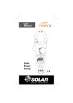
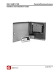
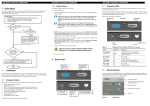
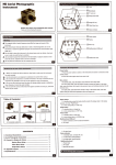
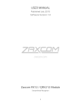
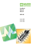
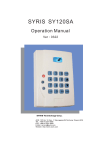
SY210NT Serial Controller Operation Manual Version 2.3 © 2005 by SYRIS Technology Corp. 1 User Manual Item Content 1. 2. 3. 4. 5. Introduction 1.1 SYNT Serial Product 1.2 System Configuration Wiring Connection 2.1 Controller to PC 2.2 Controller to Card Reader 2.3 Controller to Other Module System Setup 3.1 Power Up Procedures 3.2 System Setting 3.3 PCB Layout of Typical SY210NT Controller Programming 4.1 Set Controller Date / Time 4.2 Card Process 4.3 Set DI Parameter 4.4 DO Parameter Setting 4.5 Anti-PassBack Setting 4.6 Set Door Lock-Release Time 4.7 Set Timer, TimeZone, Holiday TimeZone 4.8 Set Application Set [APPSET] 4.9 Set Flow Process 4.10 Flow Chart 4.11 Typical Wiring Connection Technical Information 5.1 SY210NT Controller Specification 5.2 SYWIN95A Access Control Software 5.3 SYRIS Proximity Reader 5.4 Proximity Card 5.5 Power Consumption 2 1. Introduction 1.1 SY210NT Series Product 1. SY210NT2/NT4 Card Access Controller 2. SYRDS1/L5… Card Reader 3. MDDIDO Input/Output Module 4. Printer Interface Module 5. Proximity Card 6. Other Application Module 1.2 System Configuration CONTROLLER COMPUTER PROXIMITY CARD READER DOOR 1 IN OUT DOOR 2 RS485 CONNECT TO OTHER CONTROLLER MAX. 99 SETS CONNECT TO OTHER MODULE MAX. 20 SETS IN OUT RS485 DOOR 3 PRINTER MODULE AI MODULE DIDO MODULE IN OUT DOOR 4 IN OUT Figure 1.1 System Configuration 3 2. Wiring Connection Type Of Connection a. Controller to Personal Computer b. Controller to Card Reader c. Controller to Extension Module d. Input/Output Contact Build in Controller Detail Connection as follow : 2.1 Controller To PC Controller link to PC by RS485 Communication module, Maximum distance from PC to Controller is 1 KM. A single Controller M4 Connector SYLINK Connector PIN 1 4A -, Blue Color PIN 3 Green Color PIN 2 4A+, Purple Color PIN 2 Yellow Color PIN 5 GND, Black Color PIN 1 Black Color SY210NT Main PCB Board Computer PIN 3 4APIN 2 4A+ PIN 1 GND PIN1 PIN 2 PIN 5 Figure 2.1 Connection from SY210NT to PC Caution : RS485 Communication Wire must be Twisted Screen Cable, grade AWG18~24 depend on distance. 4 2.2 Controller to Card Reader Controller link to Card Reader by RS485 Communication mode, max distance from Controller to Card Reader is 1 KM. A single controller can connect up to max. 8 Readers. Controller M4 Connector PIN 3 -- 4R-, Grey Color PIN 4 -- 4R+, White Color Reader Wire Green Color 4RYellow Color 4R+ Red Color +5~12VDC Black Color 0VDC Fig 2.2 Connection from Controller to Card Reader Caution : RS485 Communication Wire must be Twisted Screen Cable, grade AWG 18~24, depend on distance. 5 2.3 Controller to Other Module 2.3.1 MDDIDO Module DIDO Module consist of : a. Power Supply …… DC : 5 ~ 12 V b. RS485 Line ….. Link to Controller 4R+, 4Rc. DO Ouput ….. 4DO, 8DO, 16DO d. DI Input ….. 4DI, 8DI,16DI DO … Dry Contact Output DI … Dry Contact Input Stalus indicate LED : LED 1 ~ 4 --- DO Output LED 5 ~ 8 --- DI Input LED 9 ---RS485 (Blinking) RELAY 4 RELAY 3 RELAY 2 RELAY 1 N C 4 N C 3 N C 2 N C 1 C O M N O 4 LE4 C O M N O 3 LE3 C O M N O 2 LE2 C O M N O 1 LE1 M2 M1 LE9 LE8 LE7 LE6 LE5 G 4 4 + R V N R D + +V: +5~+12Vdc G N D Model: MDDIDO1 Serial No: _____________ I N 4 DI 4 G N D I N 3 DI 3 G N D I N 2 DI 2 G N D I N 1 DI 1 Figure 2.3.1 DI4Do4 Module Connection Please contact factory for other DIDO Module wiring connection. 6 2.3.2 Printer Module SY200NT Controller can connect to the following printers directly or reports printing via printer module. 1. Do-Metrics Printers 2. Inkjet Printers 3. Laser Printers +V GND 4R- 4R+ +V GND 4R- 4R+ M1 LED Status Normal: Red Error: Red Flash Active: Green Flash +V: Model: MDPRINT1 5~12Vdc Serial No:__________ LED PIEZO Print Port Connect DB1 Figure 2.3.2 Connection of Printer Module 2.3.3 AI Module Please contact factory for AI Module Connection. 7 3. System Setup 3.1 Power up procedures 3.1.1 3.1.2 3.1.3 Before power up, ensure all wiring connection is correct. When the power is turned on, the controller will automatically initialize and the LED change from Green to Red with a short Beep sound. If the controller is ready, LCD will show Date/Time. 3.2 System Setting 3.2.1 Go to program mode Follow Figure 3.2.1 to go to program mode. Figure 3.2.1 How to Go to Program Mode 98/01/06 TUE13:10 System Press MENU Key Password ________ Login Press EN Key Press EN Key Login OK press CLR key 2 times to return System main screen Keyin 1234 Then Press EN Master Ok You are in program mode now. 8 3.2.2 Set Card reader ID a. Go to : [System] → [System Process]--[Change Reader ID] b. Key in Reader Serial Number and Reader ID. c. Repeat step b, to set all card reader ID. System System Process Change Reader ID Serial ___ ____ 8 number Press EN Key, Press to Select [System Process] Press EN Key, Press to Select [Change Reader ID] Press EN, Keyin Reader Serial NO Reader ID ID = [ _ ] Figure 3.2.2 Set Reader ID 3.2.3 Set Controller ID Controller ID Default Setting = 01. To set other controllers ID, follow the procedures below: System Press EN Key Then Press to Select [System Process] System Process Control ID Control ID =[ _ _ ] Key in defined controller ID ( 1~99 ) Press EN Key Then Press to select control Id Figure 3.2.3 Set Controller ID 9 3.2.4 Get Card Reader Link to Controller The linking of card reader to controller is not completed until the following step is done. Figure 3.2.4 Module Plug & Play System Module Process Press EN Key, Press to Select [Module Process] 3.2.5 Module PlugPlay Press EN Key, Press to Select [Module PlugPlay] Module Watting. Auto-detect Module Ok Store Cards I Controller Upon completion of System Setting, it is important to store all user cards in the controller. The produces is shown as below: Figure 3.2.5 Store Cards in Controller Card Add Card Process Press EN Key, Press to Select [Add Card Process] Add Card BySerial Ins Card Flash a card Press EN Key, Press to Select [Add Card By Serial] Ins Card [0001] continus flashing cards to automatically add 3.2.6 Confirmation for Systems Set Up a. The systems set up is completed after going through above steps 3.2.1 to 3.2.5. b. Press [CLR] repeatly until the LCD of controller show Date & Time. c. To confirm that the systems is properly set up, flash any of the cards previously stored in the controller to mak sure the "OK" LED lighted and the LCD show card serial number. 10 3.3 PCB Layout of typical SY210NT Controller 3.3.1 The PCB layout of SY210NT controller Door 2 Output Relay 2 Door 1 Output Relay 1 Power Supply Door 4 Output Relay 4 Door 3 Output Relay 3 DC0V DC+12V Relay Output NV Input Network Connect 5V Output 4R+ WHT or Yellow Pin3: 4A- 4R- GRN RS485 Pin2: 4A+ Connector Pin1: GND To other Reader or Module To other Controller Figure 3.3.1 The PCB Layout of SY210NT Controller 11 3.3.2 The following setting is fixed by the systems Card Reader ID Reader ID = 1 (Door 1 Entry) or 5 (Door 1 Exit) Reader ID = 2 (Door 2 Entry) or 6 (Door 2 Exit) Reader ID = 3 (Door 3 Entry) or 7 (Door 3 Exit) Reader ID = 4 (Door 4 Entry) or 8 (Door 4 Exit) Controller Output Relay 1 Relay 2 Relay 3 Relay 4 Reader ID "1" is for Door 1 Entry Reader, likewise ID "2" is for Door 2 Entry Reader, and similar to ID "3" and ID "4" Reader ID "5", "6", "7" and "8" are for Door "1", "2", "3" and "4" Exit Reader. 12 4 Programming 4.1 Set Controller Date / Time 4.1.1 Set Time System Press EN Key Then Press to Select [Change Time] Change Time Set Time Press EN key __:__:__ Press EN Key Then Keyin Time HH:MM:SS Figure 4.1.1 Set Time 4.1.2 Set Date System Press EN Key Then Press Change Date Set Date __/__/__ Press EN key Press EN Key Then Keyin Date YY/MM/DD to Select [Change Date] Figure 4.1.2 Set Data 13 4.2 Card Process 4.2.1 Store Card to Controller a. b. Logon in Controller Program Mode Store Card Procedures Card EN Add Card Process Add Card EN Operation Proceducer EN Press EN to enter Page Up/Down EN Press En to Enter Add Card BySerial Add Card in sequence EN Add Card ByNo. EN Ins Card EN EN Add Card by Serial No. Flash Card in sequence CLR Flash Card Add Card No:_ _ _ Ins Card EN Key in serial No. CLR Flash a card Function Key Page Down MENU Function Menu EN Enter Key CLR Escape to Previous Menu 0 ~ 9 FUN Number Key Shift Key Page Up Figure 4.2.1 Store Card 14 4.2.2 Delete card from Controller a. b. Logon in Controller Program Mode Delete Card Procedures Card EN Del Card ByNo. Del Card Process Del card DEl by Serial No. EN Delete All Card Del All cards EN Operation Proceducer EN Press EN to enter Page Up/Down EN Press En to Enter Del Card No:_ _ _ _ EN key in serial No. Delete [No/Yes] EN select Yes Delete One Card EN CLR Delete All Card EN CLR EN Function Key Page Down MENU Function Menu EN Enter Key CLR 0 ~ 9 Escape to Previous Menu FUN Number Key Shift Key Page Up Figure 4.2.2 Delete Card 15 4.2.3 Modify Card Data a. b. Logon in Controller Program Mode Modify Card Procedure Card Status Setting EN EN Card status APP Setting EN Modify One Card Edit Card data EN Card No. No:_ _ _ EN App set Key in No. EN EN PIN Setting EN Pin setting APB Setting EN Press EN to enter Page Up/Down EN Press En to Enter EN CLR Enable/Disable Setting Set:[ _ _ ] EN CLR App 01~16 PIN Set [No/Yes] EN card APB setting Operation Proceducer Card [Enable/ Disable] Card+Pin Enable/Disable Check APB [No/Yes] EN PIN Set PIN:_ _ _ EN CLR Define Pin EN CLR APB check Function Key Page Down MENU Function Menu EN Enter Key CLR 0 ~ 9 Escape to Previous Menu FUN Number Key Shift Key Page Up Figure 4.2.3 Modify Card Data 16 4.2.4 Show Card Number Card Code Numbers --- Fix Internal Number Card Serial Numbers --- Depend on programming Sequence a. Logon in Controller Mode b. Show Card Number Procedures Show Card Card No. Card EN Ins Card Show Card Process Show Card Code Show Card No. Show Card Serial EN Operation Proceducer EN Press EN to enter Page Up/Down EN Press En to Enter Flash Card Ins Card EN Show Serial No. EN EN Flash card to show Card Code CLR Flash card to show Card Serial No. CLR Flash card EN Function Key Page Down MENU Function Menu EN Enter Key CLR 0 ~ 9 Escape to Previous Menu FUN Number Key Shift Key Page Up Figure 4.2.4 Show Card Number 17 4.3 Set DI Parameter 4.3.1 DI Holiday Time Zone Setting a. b. c. Set DISet Logon in Controller Program Mode Go to [Time Zone] Menu, Select [Set DI Set] Programming Produces EN DiSet: ___ EN Key in DI No. (1~8) DiSet HodayTZ Set DI Holiday TZ Holday: ___ EN EN Key in Holiday No. EN Operation Proceducer EN Press EN to enter Page Up/Down EN Press En to Enter Holday: _<_ _>_ Key in TZ No. Before Holiday Holiday After Holiday Function Key Page Down MENU Function Menu EN Enter Key CLR Escape to Previous Menu 0 ~ 9 FUN Number Key Shift Key Page Up Figure 4.3.1 Set DI Holiday Time Zone 18 4.3.2 Set DI Week Time Zone a. Logon in Controller Program Mode b. Go to [Time Zone] Menu, Select [Set DI Set] c. Programming Produces Set DISet EN DiSet: ___ EN Key in DI No. (1~8) DiSet WeekTZ Set DI Week TZ EN WeekTZ: ___ Key Week No. (1~7) EN WeekTZ:_ TZ:[ _ _ ] Key in TZ EN Operation Proceducer EN Press EN to enter Page Up/Down EN Press En to Enter Function Key MENU EN CLR Page Down Function Menu 0 ~ 9 Enter Key Escape to Previous Menu FUN Number Key Shift Key Page Up Figure 4.3.2 Set DI Week Time Zone 19 4.3.3 Set DI Action Status a. Logon in Controller Program Mode b. Go to [Time Zone] Menu, Select [Set DI Set] c. Programming Produces Set DISet EN DiSet: ___ Key in DI No. (1~8) EN DiSet Module Set DI Input EN Operation Proceducer EN Press EN to enter Page Up/Down EN Press En to Enter EN Module: ___ EN Module:_ [Disable][Enable] Enable/Disable Value: 1:DI ON, Action 2:DI OFF, Action 3:DI Float, Action 4:DI Change, Action Function Key Page Down MENU Function Menu EN Enter Key CLR 0 ~ 9 Escape to Previous Menu FUN Number Key Shift Key Page Up Figure 4.3.3 Set DI Action Status 20 4.4 DO Parameter Setting 4.4.1 Set DO Holiday Time Zone a. Logon in Controller Program Mode b. Go to [Time Zone] Menu, Select [Set DO Set] c. Programming Produces Set DOSet EN DoSet: ___ Key in DO No. (01~16) EN DoSet HodayTZ Setting Holiday TZ Holday:_ EN Key in Holiday No. (1~8) Holday: _<_ _>_ EN Key inTZ Before Holiday Holiday After Holiday EN Operation Proceducer EN Press EN to enter Page Up/Down EN Press En to Enter Function Key Page Down MENU Function Menu EN Enter Key CLR Escape to Previous Menu 0 ~ 9 FUN Number Key Shift Key Page Up Figure 4.4.1 Set DO Holiday Time Zone 21 4.4.2 Set DO Week Time Zone a. Logon in Controller Program Mode b. Go to [Time Zone] Menu, Select [Set DO Set] c. Programming Produces Set DOSet EN DoSet: ___ EN Key in DO No. (01~16) DoSet WeekTZ Set DO Week TZ EN WeekTZ: ___ Key in Week No. (1~7) EN WeekTZ:_ TZ:[ _ _ ] Key in TZ No. EN Operation Proceducer EN Press EN to enter Page Up/Down EN Press En to Enter Function Key Page Down MENU Function Menu EN Enter Key CLR 0 ~ 9 Escape to Previous Menu FUN Number Key Shift Key Page Up Figure 4.4.2 Set DO Week Time Zone 22 4.4.3 Set DO Action Status a. Logon in Controller Program Mode b. Go to [Time Zone] Menu, Select [Set DO Set] c. Programming Produces Set DOSet EN DoSet: ___ Key in DO No. (01~16) EN DoSet SetType Set Action Type EN EN Operation Proceducer EN Press EN to enter Page Up/Down EN Press En to Enter SetType Type:[ _ ] Action Typr: 0: Not use 1: Always 2: by Min Function Key Page Down MENU Function Menu EN Enter Key CLR 0 ~ 9 Escape to Previous Menu FUN Number Key Shift Key Page Up Figure 4.4.3 Set DO Action Status 23 Anti-Passback Setting 4.4.2 Set APB for Individual Door a. b. 1 2 System Provide 3-Class APB Level Programming Procedures System EN System Process EN EN APBLevel Setting APB CLASS APBLevel >_-_-_-_ EN AREA:1_ 2 _3 _ 4_ KEY IN 0 1 2 3 3 SET APB CHECK LEVEL 0:IGNORE EN 1:LEVEL 1 2:LEVEL 2 3:LEVEL 3 EN Figure 4.5.1 Anti-Passback Setting 4.4.3 Set APB for Individual Card a. b. c. Program only for those cards required APB Logon in Controller Program Mode Program Procedures Card EN Modify One Card Edit Card EN EN Card No. No:_ _ _ EN Key In Card No APB Setting EN Check APB [No/Yes] EN Yes/No Set APB EN Figure 4.5.2 Set Card APB 24 4.5 Set Door Lock-Release Time a. b. c. SY200NT controller will send a signal output to release the lock (Relay 1 to 4) if a valid card is read. The setting is to determine how long you want the lock to remain open. Logon in Controller Program Mode. Program Procedures Figure 4.6 Set Door Lock-Release Time System EN EN IO Process EN IO Data Door Set Door Setting EN Door Door:[ _ ] EN Key in Door 1, 2 , 3, 4 EN Door ID_ |CH__ ID Set as 0: CH Set as 01: Door #1 02: Door #2 03: Door #3 04: Door#4 Door Time:_ _ _ EN 4.6 Set Timer, TimeZone, Holiday TimeZone 4.6.1 Set Timer a. b. c. EN Set Door LR Time (1~999) A Total of 30 Timers may be programmed. The Timers are used in other commands to set time zone Logon in Controller Program Mode Programming Procedures Figure 4.7.1 Set Timer TimeZone EN Timer Table Timer setting Timer: _ _ EN Timer No. EN Timer: _ _ Start_ _:_ _ Start Time EN 01~30 EN 25 Timer: _ _ End_ _:_ _ End Time EN 4.6.2 Set TimeZone a. b. c. d. A Total of 60 TimeZone may be programmed. Each with 3 sets of timers TimeZone is important and used in access control and DIDO programming etc Logon in Controller Program Mode Programming Procedures Figure 4.7.2 Set TimeZone TimeZone EN Timer Table Timer setting Timer: _ _ EN Timer No. EN Timer: _ _ Start_ _:_ _ Start Time EN Timer: _ _ End_ _:_ _ End Time EN 01~30 EN 4.6.3 Set Holiday TimeZone a. Holiday access control include : Holiday Eve, Holiday and day after Holiday b. To define Holiday Access Control, must go to TimeZone] Menu, select [APPSET] to set [Holiday TimeZone] first c. A total of 8 Holiday TimeZone may be set d. Programming procedures Figure 4.7.3 Set Holiday TimeZone TimeZone EN Timer Table Timer setting Timer: _ _ EN Timer No. EN Timer: _ _ Start_ _:_ _ Start Time EN Timer: _ _ End_ _:_ _ End Time 01~30 EN 26 EN 4.7 Set Application Set [APPSET] APPSET Setting List a. b. c. d. e. f. Edit Holiday TimeZone Edit Weekly TimeZone Set Out Flag (Exit control) Set Door Flag (Door Access Control) Set Security PIN Code (Common PIN) Set Personal PIN Code (APP Group PIN) APP Set Flow Chart EN TimeZone Set APPset EN EN Set APPSet Data EN Set:[ _ _ ] Set AppSet No. ( 01~16 ) EN APPSet Hoday TZ APPSet WeekTZ APPSet OutFlag APPSet DoorFlag APPSet Security Personal Set Holiday TZ Se Week TZ Set OutFlag Set DoorFlag Set Security PIN Code Set Personal PIN APPSet Figure 4.8 APP set Flow Chart 27 4.7.1 Set Holiday TimeZone a. The Controller Provides 8 Group of Holiday TimeZone, Date include Holiday Eve, Holiday and day after Holiday Logon in Controller Program Mode Programming Procedures Figure 4.8.1 Set Holiday TimeZone b. c. Set APPSet EN Set:[ _ _ ] EN APPSet HoldayTZ Holday:_ EN Set Holiday TZ Set APPSet No. (1~16 ) EN Set Holiday No. (1~8 ) EN 4.7.2 Holday:_ _ _<_ _>_ _ Holday:_ O[ _<_>_ ] EN EN Set Holiday Exit Control 0:No, 1:Yes Key in TZ for: Holiday Eve Holiday day After Holiday Set Weekly TimeZone a. b. c. To set Daily TimeZone and within a week Logon in Controller Program Mode Programming Produces Figure 4.8.2 Set Weekly TimeZone Set APPSet EN Set:[ _ _ ] EN APPSet HoldayTZ Set Holiday TZ Set APPSet No. (1~16 ) EN Holday:_ EN EN Set Holiday No. (1~8 ) Holday:_ _ _<_ _>_ _ Key in TZ for: Holiday Eve Holiday day After Holiday EN Holday:_ O[ _<_>_ ] Set Holiday Exit Control 0:Yes, 1:Nol 28 EN 4.7.3 Set Out Flag a. b. c. The function is used to set the Exit Control for individual door Logon in Controller Program Mode Programming Procedures Figure 4.8.3 Set Out Flag Set APPSet EN APPSet HoldayTZ Set:[ _ _ ] EN Holday:_ EN Set Holiday TZ Set APPSet No. (1~16 ) EN Set Holiday No. (1~8 ) EN 4.7.4 Holday:_ _ _<_ _>_ _ Holday:_ O[ _<_>_ ] EN Key in TZ for: Holiday Eve Holiday day After Holiday EN Set Holiday Exit Control 0:No, 1:Yes Set Door Fag a. b. c. The function may be used to set the access level Logon in Controller Program Mode Programming Procedures Figure 4.8.4 Set Door Flag Set APPSet EN Set:[ _ _ ] EN APPSet HoldayTZ Set Holiday TZ Set APPSet No. (1~16 ) EN Holday:_ EN EN Set Holiday No. (1~8 ) Holday:_ _ _<_ _>_ _ Key in TZ for: Holiday Eve Holiday day After Holiday EN Holday:_ O[ _<_>_ ] Set Holiday Exit Control 0:No, 1:Yes 29 EN 4.7.5 Set Security PIN Code a. b. c. The function may be used to set Card + PIN (Common PIN) Logon in Controller Program Mode Programming Procedures Figure 4.8.5 Set Security PIN Code Set APPSet EN Set:[ _ _ ] EN APPSet HoldayTZ Holday:_ EN Set Holiday TZ Set APPSet No. (1~16 ) EN Set Holiday No. (1~8 ) EN Holday:_ O[ _<_>_ ] EN Set Holiday Exit Control 0:No, 1:Yes Key in TZ for: Holiday Eve Holiday day After Holiday EN 4.7.6 Holday:_ _ _<_ _>_ _ Set Personal PIN Code a. b. c. The function may be used to set Card + PIN (Personal PIN) Logon in Controller Program Mode Programming Procedures Figure 4.8.6 Set Personal PIN Code Set APPSet EN Set:[ _ _ ] EN APPSet HoldayTZ Set Holiday TZ Set APPSet No. (1~16 ) EN Holday:_ EN EN Set Holiday No. (1~8 ) Holday:_ _ _<_ _>_ _ Key in TZ for: Holiday Eve Holiday day After Holiday EN Holday:_ O[ _<_>_ ] Set Holiday Exit Control 0:No, 1:Yes 30 EN Set Flow Process SY200NT Controller Provide: A Total of 26 Events for detection A Total of 11 Actions for Execute SY200NT will work depending on following sequence: Source (Detecting Events) Target (Action) Mode (Action Mode) Event Table Ite m 1 Card Sense 2 In Check OK 3 Out Check OK 4 Invalid Card 5 Disable Card 6 Invalid TimeZone 7 Invalid Door 8 Invalid PIN 9 10 Invalid PIN Three Time ReEntry 11 ReExit 12 KeyPad Press 13 DI On 14 DI Off Event Function Description ID (0-9) Channel (0 -60) 1-8 : Reader None ID 9 : All Module Same as None above Same as None above Same as None above Same as None above Same as None above Same as None above Same as None above Same as None above Same as None above Same as None above 1-8 : 1-10 :1-9,0 KEYPAD 11-20 : F19 : F9,F0 SY200NT 1-8 : 1-16 DI Point MDDIDO 9 : SY200NT 1-8 : 1-16 DI Point MDDIDO 31 Delay Time None None None None None None None None None None None None 0-99 Seconds 0-99 Seconds 15 DI Float 16 DI Change Status 17 DI Set On 9 : SY200NT 1-8 : MDDIDO 9 : SY200NT 1-8 : MDDIDO 9 : SY200NT 1-4 DI Point 18 DI Set Off 1-4 DI Point 19 DI Set Float 1-4 DI Point 20 DI Set Change 1-4 DI Point 21 DO Set On None 22 DO Set Off None 23 Time Out None 24 Forced None 25 Duress None 26 HardWare Error None 1-16 DI Point 0-99 Seconds 1-16 DI Point None 1-4 TimeZone Number 1-4 TimeZone Number 1-4 TimeZone Number 1-4 TimeZone Number 1-60 TimeZone Number 1-60 TimeZone Number 1-60 TimeZone Number 1-60 TimeZone Number 1-60 TimeZone Number Module No = 1-20 59 SY200NT 60 ALL None None None None None None 0-99 Seconds 0-99 Seconds None None Action Table Item Event Function 1 SY200NT 2 Set Sound 3 Set Alarm Sound 4 Set Description ID(0-9) LED Code 1 : Ok LED 2 : Error Led 3 : Set up LED 4 : Active LED 5 : BlackLight LED Sound Code 1 : Beep sound 2 : Do Sound Alarm Code 1 : Steal 2 : Emergency 3 : Fire Alarm 4 : Gas 5 : Error 6 : Duress DO Action Channel(0-60) Method(04) 1 : always 2 : 100ms 3 : sec 4 : min LED Color 1 : Dark (Blacklight Off) 2 : Red ((Blacklight On) 3 : Green 4 : Orange DO Point 1-4 : 32 Time (1-999) 1 : always 2 : 100ms 3 : sec 4 : min 1 : always 2 : 100ms 3 : sec 4 : min Time (1-999) 1 : always Time Time (1-999) System Internal DO Set DIDO Module DO Point On Set DIDO Module DO Point OFF SET DIDO Module DO Point Change Show Message 1 : Open 2 : Close 3 : Change DIDO Module ID 1-8 Door 1-4 DIDO Module ID 1-8 DO Point 1-16 DIDO Module ID 1-8 DO Point 1-16 1-8 : KeyPad Module ID 9 : Sy200NT PostMessage Code 1-16 9 Show Data 1-8 : KeyPad Module ID 9 : Sy200NT Show Data Code 1-13 See Data Code Table 10 Check Card 11 Add InOut Event : Invalid Card Disable Card Invalid Door Invalid TimeZone Invalid PIN Invalid PIN Three Time ReEntry ReExit In Check Ok Out Check Ok See Event Name 5 6 7 8 2 : 100ms 3 : sec 4 : min 1 : always 2 : 100ms 3 : sec 4 : min 1 : always 2 : 100ms 3 : sec 4 : min 1 : always 2 : 100ms 3 : sec 4 : min DO Point 1-16 (1-999) Time (1-999) Time (1-999) Time (1-999) 1 : always Time 2 : 100ms (1-999) 3 : sec 4 : min 1 : always Time 2 : 100ms (1-999) 3 : sec 4 : min If the Card + PIN is required by user or system. The event will appear after entering Password. 33 Default Flow Control Setting No Event IDEvent 1 2 3 4 Card Sense In Check Ok In Check Ok In Check Ok All Module All Module All Module All Module Check Card LED Sound Show Data Ok LED Beep SY200 5 6 7 8 In Check Ok Out Check Ok Out Check Ok Out Check Ok All Module All Module All Module All Module Add InOut LED Sound Show Data Ok LED Beep SY200 9 10 Out Check Ok All Module Invalid Card All Module Add InOut LED Chanel Event Action IDAction Chanel Method Time Action Error LED Bell SY200 11 12 Invalid Card Invalid Card All Module All Module Sound Show Data 13 14 Invalid Card Disable Card All Module All Module Add InOut LED 15 16 Disable Card Disable Card All Module All Module Sound Show Data 17 18 Disable Card Invalid TimeZone Invalid TimeZone Invalid TimeZone All Module All Module Add InOut LED All Module Sound Error LED Bell All Module Show Data All Module Add InOut 22 Invalid TimeZone Invalid Door All Module LED 23 24 Invalid Door Invalid Door All Module All Module Sound Show Data 25 26 Invalid Door Invalid ReEntry Invalid ReEntry Invalid ReEntry All Module All Module Add InOut LED All Module Sound Error LED Bell All Module Show Data SY200 Add InOut 30 Invalid All Module ReEntry Invalid ReExit All Module 31 32 Invalid ReExit All Module Invalid ReExit All Module Sound Show Data 33 34 Invalid ReExit All Module Card Sense All Module Add InOut LED 19 20 21 27 28 29 LED Error LED Bell SY200 Green Second 2 Card Second Find No 2 Green Second 2 Card Second Find No 2 Red Second 2 Invalid Card Second 2 Red Second 2 Disable Second Card 2 Second 2 SY200 Invalid Second TimeZo ne 2 Error LED Bell SY200 Red(2) Second 2 Invalid Second Door (5) 2 Error LED Bell SY200 Active LED Red Red(2) Second 2 Invalid Second ReEntry (8) 2 Red Second 2 Invalid ReExit Second 2 Red Second 2 35 36 Flow Control Instruction Following is a example of flow control after it sense a card. No Event IDEvent Chanel Event Action IDAction Chanel Method Time Action 34 1 2 3 4 Card Sense In Check Ok In Check Ok In Check Ok All Module All Module All Module All Module Check Card LED Sound Show Data 5 In Check Ok All Module Add InOut Ok LED Beep SY200 Green Second 2 Card Second Find No 2 No. 1 Ask all module (reader) of controller to read card and ask controller to check card status. No. 2 When In Check OK, (reader ID=1, entry reader) the OK LED of controller will changes to green color and active for 2 seconds. No. 3 When In Check OK, controller will create a Beep sound. No. 4 When In Check OK, the controller LCD will show card serial number and it will active for 2 seconds. No. 5 When in Check OK, controller will add a record to InOut transaction data base. 35 When the controller is "In Check OK" (Valid Card), it will active the output relay where the card is read. Following is a example of flow control using DI Point for exit button. No Event 37 DI On Flow Process IDEvent ChanelE vent 9 1 Add Flow Control Caution 1. Default Flow Control setting is 01~36,User can define new Flow Control from 037 and above 2. If some flow Control setting is deleted, the flow control sequence will be automatically updated. IDAction ChanelAction Action SY200 DO Open Method Time 1 3 3 Set delay =00 Event Setting Event DI On Event ID = [ 9 ] Event Ch:[ 01 ] Action Setting Action SY200 DO Action [ OPEN ] Action Ch:[ 01 ] Method Time Method [ SEC ] Method Time:003 To add Flow control,set event first, then set action and method As above setting table: Event = DI On : Ask controller active when DI Point is On. Event ID = 9 : the DI Point come from SY200NT internal DI. Chanel Event = 1 : DI Point is the first one. Action = SY200 DO : setting SY200 DO is for action point. IDAction = Open : set action is open. ChanelAction = 1 : output is come from DO1 Method = 3 : active time is in second Time = 3 : output active 3 seconds Program Procedures for above 36 4.10 Flowchart 98/01/08 Thu17:05 Enter Program Mode and System main program menu Press E N Enter Program Mode MENU Enter Key E N Press Page Down Or Press E N Waiting Password E N Enter Password ( 1234) E N Master Ok Default Password is Master Password, Can all system setting Press E N or or Press CLR Print Menu Alram Set Print Press Press EN System parameter System Press Press EN All InOut Alarm [Disabl/Enable] Press Press EN Print Mode Press Or Holiday Table or EN ShowCard Process Press Press or EN Press EN Set APPSet Press or EN Default card System Process EN Press or EN IO Process or or EN Press or EN TimeZone Table Del Card Process Press Print Time or EN Press or EN EN Set DO Set Press or EN Timer Table Modify One Card Module Process EN Press EN Press or TimeZone Press Press or EN Flow Process EN Time Zone Menu Add Card Process Press or Card Press or All Card Data Press CLR Card Data Menu Logout EN or Enter Follow Screen Press Press or or MENU Login Return to main screen Alarm Menu Set alarm Change Screen Password _______ Start Function Menu Press MENU Login Esc Key MENU Or Press Enter System Page Up CLR SYRIS SY200NT4 System or EN EN Set DI Set Operator Process Next Page 37 Flowchart continue System Previous page Message Process Press or EN Idle Screen Press or EN Change Time Press or EN Change Date Press or EN Software Reset Press or EN Show OS Version Press or EN Alarm Test Press or EN Login Press or EN Logout 38 4.11 Typical Wiring Connection Door 1 Alarm Output Door 2 Alarm Output Door 1 EM-Lock Door 2 EM-Lock SY200NT4 DC 12~15V DC 0V Door 2 Sensor Door 1 Sensor Door 2 Exit Button Door 1 Exit Button 4ABlk 4A+ Yel Red Door 2 Entry Reader 4R+ 4R- 39 Grn Connect to PC Yel Red Door 1 Entry Reader Grn Blk 5 Technical Information 5.1 SY210NT Controller Specification SY210NT Controller Specification Items / Spec Number of Cards Number of Readers Door Control Reader Technologies User P.I.N. code Input Points Control relay Output Communication ports Baud rate Programmable time zone Group (application set) Holidays Controller ID Expand modules Anti-passback Keypad input Keypad backlight LCD display Speaker output Indicator Operating temperature Storage temperature Power supply input Power consumption Dimensions (mm) 5.2 SY210NT2 9,999 4 (2In,2Out) 4 SYRIS RS485 format 4 digital code Normally 4, Expandable to 64 Normally 2, Expandable to 64 RS485, 2 Ports 19,200 bauds 60 time zone 16 366 01-99 SYRIS NT Serial Module Up to 3 level of local and / or group anti-passback 16 key keypad Built-in 8 x 2 LCD with backlight Maximun 0.2 W 5 LED 2 C to 55 C -25 C to 85 C DC 11V to 20V 1W to 10W 107W x 150H x 27D SYW95A Access Control Software • • • • Link up to 99 Controllers, 396 doors, 792 Readers 3 level of anti-passback User define language 6000 card holders 40 SY210NT4 9,999 8 (8In,8Out) 4 SYRIS RS485 format 4 digital code Normally 4, Expandable to 64 Normally 4, Expandable to 64 RS485, 2 Ports 19,200 bauds 60 time zone 16 366 01-99 SYRIS NT Serial Module Up to 3 level of local and / or group anti-passback 16 key keypad Built-in 8 x 2 LCD with backlight Maximun 0.2 W 5 LED 2 C to 55 C -25 C to 85 C DC 11V to 20V 1W to 10W 107W x 150H x 27D 5.3 SYRIS Proximity Reader SYRIS Proximity Reader Specification ♦ ♦ ♦ Water resistant, high security, high durability, and low identification error rate. Can be mounted directly on metal without affecting its reading performance. SYRIS proximity reader is able to interface with all existing access control system by WiegandTM formats, RS485 formats or etc. Items / Spec Frequency Card (Transponder) Reader range* Card read time Output interface Color Operating temperature Storage temperature Power supply input Dimensions (mm) SYRDS1-485 (SYRDSSS1) 125KHz SYRIS card 5cm ~ 15cm 0.1sec (typical) SYRIS RS485 formats Beige or dark-grey 2 C to 55 C -25 C to 85 C 5V ~ 15Vdc 75W x 115H x 15D SYRDS1-W26 (SYRDSSW1) 125KHz SYRIS card 5cm ~15cm 0.1sec (typical) SYRIS RS485 formats Beige or dark-grey 2 C to 55 C -25 C to 85 C 5V ~ 15Vdc 75W x 115H x 15D Items / Spec SYRDL1-485 (SYRLSSS1) SYRDL1-W26 (SYRLSSW1) Frequency 125KHz 125KHz Card (Transponder) SYRIS card SYRIS card Reader range* 4cm ~ 12cm 4cm ~12cm Card read time 0.1sec (typical) 0.1sec (typical) Output interface SYRIS RS485 formats SYRIS RS485 formats Color Beige or dark-grey Beige or dark-grey Operating temperature 2 C to 55 C 2 C to 55 C Storage temperature -25 C to 85 C -25 C to 85 C Power supply input 5V ~ 15Vdc 5V ~ 15Vdc Dimensions (mm) 41W x 140H x 20D 41W x 140H x 20D *The specification is preliminary and is subject to change without prior notice. Note: *Reading range is subject to card type, site interference and antenna specs for more information. 5.4 Proximity Card (Transponder) Card (transponder) Specification ♦ ♦ No battery needed for all card (transponder) SYRIS proximity reader recognizes over 4 billion unique codes Items / Specs Thick card ISO card Key chain Model number SY-Prox-1 SY-ISO-1 SY-Key-1 Read range 5cm~15cm 5cm~15cm 2cm~8cm Dimensions(mm) 86*55*1.9 86*54*0.76 24.5*33.5*4.7 Color White/Dark-grey White Beige/Dark-grey 41 Key chain SY-Key-2 2cm~8cm 17*45*8.2 Beige/Dark-grey 5.5 Power Consumption (DC12V) Items / Spec Controller Card reader Printer Module DIDO Module Power consumption per unit 400ma 100ma 100ma 250ma 42