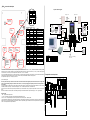
1
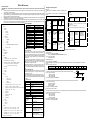
“Elfin”-MM fast index Function description: “Elfin”-MM “Elfin” is integrated with time recorder, PWD door controller, single-door controller, reader with Chinese character display and double door controller. One build-in card reader, two sets of W26 interface, two sets of sensor input, two sets of open button input, two sets of relay output, one set of bell port and one set of RS485 communication interface. Chinese-English Menu port with backlight; display the owner’s name and work number, send public short message and personal short message; the alarm supporting working day setting, set equipment parameter by keyboard, off-line operation, support 2500 card holders, store 25000 pieces of card reading information and alarm event and network with 255 machines. Flexible application can re-define the IO interface. For example, W26 port will be defined as W26 standard output or input, the relay can be defined as door controller, bell or alarm output, the sensor can be defined as fire ALMsignal. Professional door controller functions: 32 time periods/64 time sets/16 application groups/8 types of holidays/validity period for card; when the hard is off-line, there are two layers of A.P.B protection; Only PIN, only card and card & PIN are available; soft control of any door, various alarm incidents functions: open time-out, close time-out, intrude alarm, force alarm, burglar alarm and fire ALM etc. Technical parameters Menu_Main Data saving Off-line capacity Card control Card type Working voltage Power consumption Induction distance Reading speed Communication mode Networking capacity Working temperature Working humidity Storage temperature LCD display Dimension Weight |—Clock | |—Set time | |—Adj time | | |— Adj not | | |— Adj fast | | |— Adj slow | |—Alarm clock | | | | | |—Enable | | | |—Alarm | | | |—Delay | | | |—WeekSet Sunnday Monday… Saturday | | | | | |— CLK 16-> (Ditto) |—CLK 01-> 。 。 。 Keyboard operation description: |—Card | |—Add card | |—Update card | |—Del card |—System | Ten years (after power failure) 25000 pieces (adjustable) 2500 pieces (adjustable) EM card (MIFARE is optional) 8~25VDC <3W 6—15cm 0.15 second RS485 255 sets -20℃—70℃ 20%—90% -25℃—85℃ 122×32DOTS L120×W88×H 18mm 160g |—Model ID | |—Llight mode—NC.、NO.、AUTO、SetTime | |—Beep hint—Keys、 Clock、 Hints, | |—Baud rate—2400bps、4800bps、9600bps、19200bps | |—Rec. option— In rec.、 Out rec.、 Events、Cycle、 | | | |—Menu PWD Sameness、 Tol. alarm、5 Digit | |—Sys info | |—Clear… | |—Updata… |—Door | |—Door1 | | |—Authority | | | |—Timer—(0-31) | | | |—TimeZone—(0-63) | | | |—Holiday | | | |—APPSet—( 0-15) | | |—Control mode—In & Out、 Only in、 Any out 、A.P.B. | | |—Entry type— Only card、 Only PIN、 Card &PIN | | |—Sensor type— Sensor NO、 Sensor NC、Fire NO、Fire NC、NULL | | |—Button type—NO.、NC.、NULL | | |—OpenTime | | |—CloseTime | | |—First NO.— ON、 OFF | | |—Duress PIN | | |—Access PIN | |—Door2 | | | |— Door1->2 | |— Door2->1 (Ditto) menu operation guide: Go menu: press <*> and <#> (<*> first, then <#> soon after) at the initial state to enter into the menu state (press valid PWD if it is set password). If you don’t press the button within 3 minutes, the system will automatically escape from the menu and restore the initial interface. When the system is in the menu state, it will give no response to the door controller and RS485 communication. Menu browse: the menu is in tree structure. In some submenu, <7> and <9> are used to choose the items up and down. The chosen item will be in white display. Press <#> key to fix the item setting, press <*> to cancel the item setting and return to the high-authority menu. Multiple choice and single choice: <7> key is to review upward, <9> key is to review downward; <#> key is to choose multiple choices or single choice; < * > key is to escape the multiple choice or single choice and save the choice result. Operation guide for PWD entry: Press <#> at the initial state and the screen displays the prompt to enter the password. Enter the PWD (from <0> to <9>) (Access PIN or Duress PIN), and press <#> key to confirm. PWD modification: read card and press the valid password, then press <*> and <#>, stamp card again at the sight of the prompt quickly. Enter the new PWD two times. The personal PIN modification is successful. (Default PWD is: 888888) 1、Display icon index Icon Meaning Current option There is some information following, press < 9 > to review. There is some information above, press < 7 > to review. There is no chosen item in the check box. There is chosen item in the check box. There is no chosen item in the radio button. There is chosen item in the radio button. 2、 keyboard function index Key < 0 >< 1 >< 2> < 3 >< 4 >< 5 > < 6 >< 8 > <7> <9> |—IO port | |—Relay 1—Lock 1、 Lock 2、 Bell、 Alarm 、 NULL | |—Relay 2—Lock 1、 Lock 2、 Bell、 Alarm 、 NULL | |—W26 Port1— In 1、 Out 1、 In 2、 Out 2、 W26 out 、 NULL | |—W26 Port2— In 1、 Out 1、 In 2、 Out 2、 W26 out 、 NULL | |—Self Reader— In 1、 Out 1、 In 2、 Out 2、 NULL |—Language— Chinese,English <*> <#> Function Number input Number 7 input Up Number 9 input Down Cancel the operation Return to the high-authority menu Escape multiple choice or single choice and save the choice. Confirm the operation Enter into the submenu Choose multiple choices or single choice. Authority and card management Setting steps 1. Set time period list>> set SetTimelist>> set holidays>> set application groups 00-15 2. Card management-> add card or modify card, set the validity period of the card and. Authority APPSet 00 . . . . . . . . . APPSet 15 APPSet for DR 1 00——15 APPSet week number Sun. 00 Mon. 00 … Sat. 00 TimeZone 4periods number 00 00 00 00 00 . . . . . . . . . . . . . . . 00 00 00 00 63 holiday type H-Type 0 00 … H-Type 7 00 APPSet for DR 2 00——15 Holiday Date Type 00MM00DD 00 . . . APPSet case case 1 pass for 24 hours APPSet all set as 00 PWD validity period Card Timer start end number 00:00 ->00:00 00 . . . . . . . . . 00:00 ->00:00 31 Note: the number in thick and inclined is adjustable. TimeZone 00 00 00 00 00 Timer 00:00 ->23:59 00 case 2 Mon–Friday: 8:00——12:00, 14:00——17:00 and 20:00——23:30 are the entrance time period. Saturday: 8:00——12:00 entrance time Sunand holiday (such as the National Day): no entrance for whole day APPSet Sun Mon Tues Wed Thur Fri Sat H-Type 0 00 01 01 01 01 01 02 00 TimeZone 00 00 00 00 00 01 02 03 00 01 01 00 00 00 02 Timer 00:00 ->00:00 08:00 ->12:00 14:00 ->17:00 20:00 ->23:30 00 01 02 03 Holiday Date Type 10MM01DD 00 distribute corresponding APPto the two doors Authority Examples for common use setting: Note: the following setting is based on the default setting. 1.PWD door controller 1) Door->Door1-> Entry type (set as Only PIN) ->Door1 (set as Duress PIN, Access PIN and OpenTtime respectively) 2) IO port ->Relay 1(set as Lock 1) ->Self reader (set as In1) 2. Standard wiegand chuck 1) IO port -> W26 port1(2) (set as W26 out) After setting and reading card, the port JP2(3) outputs the “card” of W26 standard format. What’s more, the key is compatible with the chuck of Motorola and HID. The key output codes are shown as follow: Key 0 1 2 3 4 5 6 7 8 9 * # Code output (binary) 0000 0001 0010 0011 0100 0101 0110 0111 1000 1001 1010 1011 See the order for signal in the right picture. 0.2ms 3. Control two doors and press PWD after reading card (connecting w26 reading head with two passwords) DATA0 1) IO port -> W26 port1 (set as In 1) ->W26 port2 (set as In 2) 2ms ….. ….. ->Relay1 (set as Lock1) ->Relay2 (set as Lock 2) DATA1 2) Door ->Door1-> Entry type (set as Card & PIN) 4. The one who enters by reading card is permitted be out by reading card and the alarm for going to and off work is needed. 1) IO port ->W26 port1 (set as In 1) ->W26 port2 (set as Out 1) ->Relay1 (set as Lock1) ->Relay2 (set as Bell) 2) Door->Door1->Control mode(set as A.P.B) 3) Clock -> Alarm clock (set as you desire) 5. There is one entry and one exit in one parking lot. The card reading is necessary when entering and going out the lot. But the vehicle that isn’t registered by card reading in the entry is forbidden to park in the lot. 1) IO port -> W26 port1 (set as In 1) ->W26 port2 (set as In 2) ->Relay1 (set as Lock1) ->Relay2 (set as Lock 2) 2) Door->Door1->Control mode(set as A.P.B) 3) Door->Door2->Control mode(set as A.P.B) “Elfin” connection description electri c lock Remark Positive power terminal, +12DC is recommended. power ground sensor 1 open button 1 sensor 2 Open button 2 relay output 1 optional open button 1 A relay output 2 sensor or fire ALM input 4 10 JP1 12 JP5 LS2’ LS2 LS1’ RS485 bus connecting next “Elfin” Example for connection picture ● GND RS485- RS485+ RS485+ PIN2 PIN1 RS485- DATA1 NC. Lock GND DATA0 DATA1 6 PUSH GND +12V COM NC NO po 5 we r 4 for 3 do 2 or 1 co ntr oll er GND OR +V +V GND ● NO. Lock JP4 interface GND JP2 or JP3 port DATA0 Hardware updata “Elfin” support hardware updata on-line. 1.“Elfin” communication port connects with computer through RS232/RS485 converter. 2. When “Elfin” in the updata standby state, the menu operation is shown as follow: system -> software updata 3. Install “Updata tool for hardware” in the computer. Operate Updata.exe, communication port should choose correct interface, the baud rate is 19200, the updata file should be the xxxxx.upd updata file provided by the manufacturer. When the updata starts, progress bar indicates the course of updata. Please do not interrupt the course. After the updata, terminal computer will reboot. 1 RS232/RS458 converter JP1 interface System connection picture Note: The power terminals (+V) of JP2 and JP3 are the same as that of JP1. When the terminal supplies power to the exterior chuck, the +V voltage should not be over the rated working voltage of the exterior chuck. In this case, it is necessary to supply power separately and then connect the ground lines of the two powers. JP1 is the main interface: including power, open button, sensor and relay output. Among them, sensor and relay output is all-purpose interface. The sensor can set as fire ALMlink, in another word, the port receives the fire ALMsignal, “Elfin” controller will open all doors of its controller doors. The relay can be set as lock control output, alarm output and alarm output. The NCand close of relay are optional of Jumper cable JP6 and JP7. See the picture above. Name and work number of card holder; issue of short message and change of title should network with computer to manage it by “Elfin” applied software. 4 RS458 总线 RS232 +V JP5 is bell interface: BPA and BPB is in open circuit. When pressing the round bell in the low left corner of “Elfin” panel, the BPA and BPB is circulating. Then BPA and BPB can connect with radio or wireless bell. JP4 is RS485 communication interface: the computer can control many “Elfin” (255 sets at most) by RS485 converter. Therefore, It is necessary to set an unique machine number for the “Elfin” in the network. JP2, JP3 are the W26 interfaces: the port is a multi-functional port and can be W26 input or W26 output. When set as input, it can connect with standard W26 card reader (support read head with keyboard). When set as output, it can be used by the standard W26 card reader for other purposes. The specific menu setting: IO port -> W26 port1(2)-> W26 out 1 1 3 JP4 LS1 Remark bell switch signal (NO) V DC power Remark positive power terminal power ground W26 data line W26 data line Remark power ground negative RS485 positive RS485 JP3 JP2 sensor or fire ALM input OP2 jumper line for relay 1 Jumper line 1-2: NO Jumper line 2-3: NC bell GND 123 2 GND red 3 MC1 green 4 OP1 yellow 5 MC2 white 6 OP2 brown 7 LS1 blue 8 LS1’ pepper 9 LS2 orange 10 LS2’ gray Description for JP2, JP3 port signal Terminal Signal Color 1 +V red 2 GND black 3 DATA0 green 4 DATA1 yellow Description for JP4 port signal Terminals Signal Color 1 GND black 2 RS485green 3 RS485+ yellow Description for JP5 port signal Terminal Signal Color 1 BPA white 2 BPB gray alarm optional Optional +V 123 relay 1 movement, LED indicates. reader 12 JP5 MC2 jumper line for relay 2 option jumper line 1-2: NO jumper line 2-3: NC relay 2 movement, LED indicate keyboard connectio n seat Wiegand 26 Out JP1 Description for JPI port signal Terminal Signal Color 1 +V red line interface manual re-set switch 1 3 JP4 10 Wiegand 26 Out OP1 liquid crystal contract adjustment 4 MC1 anti-disasse mble switch 1 GND 1 4 +V 1 System connection figure JP3 JP2 Open Button ● Wiegand26 reader RS232/485 converter bell