1
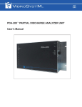
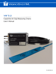
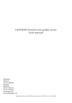
PES-305 SEALED EDDY CURRENT PROXIMITY SENSOR User’s Manual Safety Information The following manual contains information and warnings that must be observed and followed in order to keep instruments in good condition and insure safe operation. Safety and Electrical Symbols Warning - Danger - Identifies conditions or practices that could cause physical harm or damage the measuring chain and other equipment to which it is connected. Caution - Identifies conditions or practices that could result in a permanent loss of data. Important Information - Must be read and followed. Shield connection location. Safety Precautions Warning - Danger • • • • Caution To use the described sensors correctly and safely, read and follow all safety instructions or warnings displayed throughout this manual; This product is intended to be used by qualified operators and maintenance personnel who are familiar with the safety precautions required to avoid possible injury. Carefully read and follow all installation information before using this product; Install and use this product only as specified in this manual or the protection provided by this instrument might be impaired; When in doubt that safety protection has been impaired, make this product inoperative and secure it against any unintended operation; This manual is provided solely for guidance. VibroSystM Inc. takes no responsibility or liability for any damage caused by accidents, improper installation or misuse. Liability is limited to the repair and/or replacement of defective products. VibroSystM Inc. 2727 Jacques-Cartier E. Blvd, Longueuil, QC, Canada J4N 1L7 | Phone: 450 646-2157 | U.S. Toll-free Line: 800 663-8379 Email: [email protected] | www.vibrosystm.com 2 Copyright © VibroSystM Inc., 2014 PES-305 - User’s Manual P/N 9431-09M5A-101 TABLE OF CONTENTS 1. OVERVIEW OF THE PES-305 PROXIMITY SENSOR ........................................................ 5 1.1 Description .................................................................................................................................................. 1.2 Main Unit Interventions .............................................................................................................................. 5 5 2. OPERATING THE PES-305 PROXIMITY SENSOR ............................................................ 6 2.1 Connecting the PES-305 Sensor ................................................................................................................. 2.2 Assessing the Actual Sensitivity ................................................................................................................. 6 6 3. SENSOR INSTALLATION INFORMATION ......................................................................... 10 3.1 Positioning the Sensors ............................................................................................................................... 3.2 Typical Installation ..................................................................................................................................... 10 10 4. GENERAL SPECIFICATIONS ............................................................................................. 11 5. TEMPLATE FOR RECORDING DISTANCE VALUES VS Iout........................................... 13 PES-305 - User’s Manual 3 4 PES-305 - User’s Manual 1. OVERVIEW OF THE PES-305 PROXIMITY SENSOR 1.1 Description PES-305 proximity sensors are designed for measuring the relative distance between the sensor’s sensing face and metallic target surfaces. Its housing is sealed to sustain pressure up to 10 Bars [150 PSI] when submerged in oil, with a submersible integral cable. The PES-305 covers a 0 to 5 mm [0 to 197 mils] measuring range. PES-305 Sensor Integral Cable PES-305 Sensor Nut Nut Sensing Face 1.2 Main Unit Interventions Sensor holder must be bolted or welded at the appropriate location; The sensor’s integral and extension cable must be routed and protected from the sensor to the acquisition unit. • • Caution • • Instructions for sensor installation and connection must be thoroughly followed to ensure a safe and proper operation; In order to complete the commissioning, VibroSystM must be contacted when Section 2.2 (Assessing the actual sensitivity) is reached. PES-305 - User’s Manual 5 2. OPERATING THE PES-305 PROXIMITY SENSOR 2.1 Connecting the PES-305 Sensor Connect the sensor as displayed in the following wiring diagram: Wiring Diagram Important Information ANALOG OUTPUT Vdc: Power Supply A1: Voltage Output BROWN A2: Current Output 0V: Common • The integral cable shield IS NOT connected to the sensor’s metallic casing body. It must always be grounded on the instrumentation side. BLACK GND: Grounding Wire WHITE BLUE SHIELD GND RL1: Load at Voltage Output RL2: Load at Current Output 2.2 Assessing the Actual Sensitivity PES-305 proximity sensors are calibrated to produce a linearized output based on an FE360 steel target. Because the sensitivity of eddy-current sensors is affected by the nature of the material used as a target, the actual sensitivity must be experimentally determined. Important Information • Failure to correctly assess and compensate the sensitivity will result in incorrect measurement results as displayed in the illustration below. PES-305 Calculated Distance vs Sensor Current Output Incorrect Calculated Distance Without Compensation) Correct Calculated Distance (With Compensation) Real Distance vs Sensor Output 6 PES-305 - User’s Manual Important Information • • Step 1 must be completed BEFORE installing the sensor. Steps 2, 3, and 4 must be completed AFTER installing the sensor; In the examples below, calculations are in metric format. All distances can also be measured in inches with the resulting values used in the same formulas. Step 1 - Measuring Current Output (Iout) and Corresponding Distance To assess the sensor’s actual sensitivity, physical distance and current measurements must first be taken using a target made of the same material as the real target. Minimum dimensions for the target are: 50mm x 50mm x 2mm [2̶ x 2̶ x 1/16̶]. Proceed as follows: Fill the table with measurements (distance vs current), equally distributed on the full current scale. Add non- metallic spacers between the sensor’s tip and the target until Iout max. is approximately reached. Note down the current value and the distance (total thickness of spacers) in the table. Gradually remove spacers to approximately reach the next Iout level and again, write down the current value and distance. Repeat until the table is filled. The last Iout value is measured without spacers (0mm), with the sensor’s tip placed directly against the target. Recorded Distance Values vs Iout for PES-305 Ideal level of Iout (mA) 20 16.3 13.3 10.9 6.7 Measured Iout (mA) Measured distance (mm) 0 Example of Recorded Distance Values vs Iout for PES-305 Iop approx. Iout B Measured Iout (mA) Measured distance (mm) Iout A 20.3 17 13.7 10.5 5.8 5 3.6 2.5 1.6 0 dB dA PES-305 - User’s Manual 7 Step 2 - Taking a Measurement with the Sensor Installed With the sensor now installed, take a measurement and note the real operating current ( Iop). Important Information • For best results, the sensor should be installed at a distance corresponding to the middle of the measuring range when the target is stationary (unit stopped). Example with PES-305: Iop= 13.7 mA Step 3 - Calculating the Sensitivity Select two points in the table, on either side of the value closest to Iop . These two points (A & B) will be used to define the linear equation. The selected points should be at equal distance from Iop (ideally, point A at Iop - 2.5 mA, and point B at Iop + 2.5 mA). If Iop = 13.7 mA: Iop - 2.5 mA= 11.2 mA (closest correspondence in the table: Iout A = 10.5 mA, dA = 1.6 mm) Iop + 2.5 mA= 16.2 mA (closest correspondence in the table: Iout B = 17 mA, dB = 3.6 mm) Point A: Point B: a) Calculate «m» (the sensitivity or gain), using selected points A and B. Example for PES-305: dB – dA m = ------------------------------I outB – I outA 2 33.6 6 – 0,6 0,7 1.6 m = --------------------------- = ------6.5 17 – 13,3 10.5 16,6 3,3 = 0.308 b) Calculate «b» (the y-intercept) of the linear equation, using calculated «m», measured current Iout and measured distance «d» corresponding to point A, or point B. b = d – m u I out Example for PES-305 (with point B): = -1.636 mm b = 3.6 3,6- (0.308 x 17 ) c) The equation to calculate the compensated distance corresponding to the sensor’s current output is: d C = m u I out + b Where: dC is the calculated distance (in mm) 8 PES-305 - User’s Manual d) Verify the «m» and «b» calculated values by applying the following formula on the measured value between the A and B coordinates: for Iout = 13.7 mA, verify that dC = 2.5 mm (± 5% of range): d C = (0.308 0,212xu13.7) 15,04-1.636 – 2,219 = 2.58 mm Step 4 - Adjustment Through the ZOOM Configuration Software Proceed with the final adjustment through the ZOOM Configuration software. Select Sensor Configuration, and in the Range tab of the dialog window, enter the Maximum and Minimum values of the Raw output range. Formulas for Adjustment of the Raw Output Range Maximum = (m x 20 mA) + b Minimum = (m x 6.67 mA) + b Note: In the Trending and alarm range section, the Maximum and Minimum values must be within the limits of the Raw output range. Example with Calculated Values Maximum = (0.308 x 20 mA) - 1.636 4.52 0.42 Minimum = (0.308 x 6.67 mA) - 1.636 PES-305 - User’s Manual 9 3. SENSOR INSTALLATION INFORMATION 3.1 Positioning the Sensors Caution • The PES-305 sensor must be properly connected with its cable well protected to avoid any sort of mechanical damage. Before determining where to install the sensor, consider the following: The sensor’s surface must face the target; The maximum cable length (integral cable + extension) must be considered. From the sensor to the acquisition unit, the maximum distance is 300 m [984 ft] for the current output, and 100 m [328 ft] for the voltage output. • • Important Information • VibroSystM recommends relying on the services of a trained technician for supervising the installation of these proximity sensors and finalizing the ZOOM Software configuration. 3.2 Typical Installation Metal-Free Zone Metallic Surface Tightening Nut 24 mm [0.94"] M12 x 1.5 Tightening Flat M18 10 PES-305 - User’s Manual 4. GENERAL SPECIFICATIONS Operation • Measurement Type Connection Non-Contact Proximity, Eddy Current • Integral Cable Type 4-Wire x 0.34 mm2 [22 AWG] Shielded PUR (Polyurethane) • Measuring Range* 0 to 5 mm [0 to 197 mils] • Outputs* 6.67 to 20 mA 1.67 to 10 V Outer Jacket Material Outer Jacket Diameter 5.9 mm [0.232 in] • Sensitivity* 2.67 mA/mm [67.7 μA/mil] 1.67 V/mm [42.3 mV/mil] Length 30 m [98.4 ft] Min. Bending Radius 60 mm [2.36 in] • Accuracy** ± 10% • Max. Cable Length • Repeatability ± 5% • Bandwidth 0 to 1000 Hz (-3dB) For Current Output 300 m [984 ft] • Load at Current Output 500 max. For Voltage Output 100 m [328 ft] • Load at Voltage Output 10 k min. (Integral + Extension) • Temperature Drift < 10% Environment • Short Circuit Protection Built-In • Temperature Range • Certification GOST Russia - Pattern Approval Certificate for Measuring Instruments Power Requirements • Voltage 15 to 30 Vdc • Consumption 30 mA max. • Voltage Reversal Protection Built-In • Warm-Up Time 5 Minutes Operating 0 to 70°C [32 to 158°F] Storage -25 to 70°C [-13 to 158°F] • Max. Submersible Pressure 10 Bar [150 PSI] • Protection Rating IP69 Physical Characteristics • Sensor Body Chrome-Plated Brass • Sensing Face Polyamide-imide *Target material: FE360 steel Dimensions SENSING FACE **With appropriate correction factor INTEGRAL CABLE PES-305 - User’s Manual 11 12 PES-305 - User’s Manual 5. TEMPLATE FOR RECORDING DISTANCE VALUES VS Iout Unit no.: ________ Sensor S/N: ______________________ Position: _______________________ Measured Iout (mA) Measured distance (mm) 0 Unit no.: ________ Sensor S/N: ______________________ Position: _______________________ Measured Iout (mA) Measured distance (mm) 0 Unit no.: ________ Sensor S/N: ______________________ Position: _______________________ Measured Iout (mA) Measured distance (mm) 0 Unit no.: ________ Sensor S/N: ______________________ Position: _______________________ Measured Iout (mA) Measured distance (mm) 0 Unit no.: ________ Sensor S/N: ______________________ Position: _______________________ Measured Iout (mA) Measured distance (mm) 0 Unit no.: ________ Sensor S/N: ______________________ Position: _______________________ Measured Iout (mA) Measured distance (mm) 0 PES-305 - User’s Manual 13