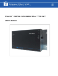
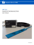
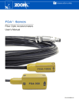
1
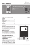
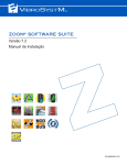
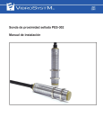
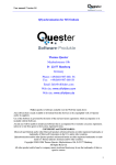
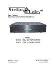
XPSP-224 EXTERNAL POWER SUPPLY PANEL FOR
MEASURING CHAINS
User’s Manual
(P/N: 9418-05I1A-102)
The VibroSystM logo is a registered trademark of VibroSystM Inc.
This guide is provided solely for guidance. VibroSystM Inc. takes no responsibility or liability for any damage caused by accidents, improper installation or misuse. Liability is limited to
the repair and/or replacement of defective products.
VibroSystM Inc. 2727 Jacques-Cartier E. Blvd, Longueuil, QC, Canada J4N 1L7 | Phone: 450 646-2157 | U.S. Toll-free Line: 800 663-8379
Email: [email protected] | www.vibrosystm.com
2 Copyright © VibroSystM Inc., 2014
XPSP-224 External Power Panel - User’s Manual
TABLE OF CONTENTS
1. GENERAL SAFETY INFORMATION...................................................................................
5
1.1 Safety information.......................................................................................................................................
5
2. GENERAL DESCRIPTION OF XPSP-224 ...........................................................................
7
2.1 Features and functionalities ........................................................................................................................
2.2 Overview of the main components .............................................................................................................
7
8
3. XPSP-224 EXTERNAL POWER SUPPLY PANEL INSTALLATION ..................................
9
3.1 Preliminary considerations..........................................................................................................................
3.1.1 Connecting the power source to the XPSP-224 unit ..........................................................................
3.1.2 Connecting the measuring chains.......................................................................................................
3.1.3 Turning the power back on.................................................................................................................
3.1.4 Maintenance .......................................................................................................................................
3.2 XPSP-224 - General Specifications ............................................................................................................
9
9
10
10
10
11
XPSP- 224 External Supply Panel - User’s Manual
3
4
XPSP- 224 External Supply Panel - User’s Manual
1. GENERAL SAFETY INFORMATION
1.1 Safety information
This manual contains information and warnings that must be observed to keep the instruments in a safe
condition and ensure safe operation.
Warning - Danger messages identify conditions or practices that could cause bodily harm, and
result in damage to this instrument and other equipment to which it is connected
Caution messages identify conditions or practices that could result in permanent loss of data.
Warning - Danger
•
•
•
To use VibroSystM instruments correctly and safely, read and follow all the safety instructions
or warnings given throughout this manual.
To avoid electric shock, personal injury, or death, carefully read the information under “Safety
Information” before attempting to install, use, or service this instrument.
In addition, follow all generally accepted safety practices and procedures required when
working with and around electricity.
Safety Precautions
Warning - Danger
To avoid possible electric shock, personal injury, or death, read the following before using this
instrument and all associated instrumentation.
•
•
•
•
•
•
Although most instruments and accessories are normally used at non-hazardous level voltages,
hazardous conditions may be present in some situations.
This product in intended for use by qualified operators and maintenance personnel who recognize shock
hazards and are familiar with the safety precautions required to avoid possible injury. Read and follow all
installation, operation, and maintenance information carefully before using the product.
Install and use this instrument only as specified in this manual, or the protection provided by this
instrument might be impaired.
Do not use this instrument in wet environments.
Whenever it is likely that safety protection has been impaired, make this instrument inoperative and secure
it against any unintended operation.
Have this instrument serviced only by qualified service personnel.
XPSP- 224 External Supply Panel - User’s Manual
5
•
•
•
•
•
•
To avoid shock hazard, connect the power supply to a properly grounded line power source. If a twoconductor power cord must be used, a protective grounding wire must be connected between the ground
terminal and earth ground before connecting the power cord or operating the instrument.
Never remove the cover of the power supply module without first turning off the main power source.
Do not operate this instrument with the cover of the power supply removed.
Use caution when working with voltages above 30 Vac rms, 42 Vac peak, or 42 Vdc, as these voltages
pose a shock hazard.
Use only the replacement fuse(s) specified by the manual.
Do not operate this instrument around explosive gas, vapor, or dust.
Safety and electrical symbols that appear in this manual and on this instrument:
Warning - Danger - identify conditions or practices that could cause bodily harm, and result
in damage to the measuring chain and other equipment to which it is connected. Conditions
include a risk of electric shock (voltage > 30 VDC or VAC peak might be present).
Caution - identify conditions or practices that could result in permanent loss of data.
Protective conductor terminal
Electronics common - not linked to earth ground
(Shield) cables shield-to-earth ground, frame or chassis terminal - linked to earth ground
6
XPSP- 224 External Supply Panel - User’s Manual
2. GENERAL DESCRIPTION OF XPSP-224
2.1 Features and functionalities
The XPSP-224 External Power Supply Panel is designed to provide 24 VDC for up to 16 measuring chains
and one synchronization probe, and connection points for each returning signal. The maximum load of the
combined measuring chains is 4 Amp.
The Panel mounts at the back of an instrumentation rack near its corresponding ZPU-5000 and/or PCU-5000
unit. Screw terminals provide easy connection of measuring chains to the instrumentation units and power
supply of the panel. The main power input terminal blocks are fuse protected.
Features
•
•
•
•
•
•
Provides +24 VDC power for up to 16 measuring chains
Independant screw terminals for each individual measuring chain
Maximum load: 4 Amp total
Universal power supply input: 100 - 240 VAC (50 - 60 Hz), or 105 - 250 VDC
Input terminal blocks with fuse protection
3U high (13.3 cm / 5.25 in.) panel, standard width rack (483 mm / 19 in.)
XPSP- 224 External Supply Panel - User’s Manual
7
2.2 Overview of the main components
The unit is designed to be installed in a properly ventilated rack mount enclosure.
Overall dimensions (without mounting brackets) are:
483 W x 140 D x 133 H (mm)
19” W x 5.5” D x 5.25” H (inches)
1
1
6
3
6
4
2
5
1 Terminal blocks
A series of multi-level terminal blocks allow connection of up to sixteen measuring chains, plus one dedicated
channel for synchronizaton probe connection.
2 Power module
The power module provides + 24VDC output, maximum nominal output current of 4A.
3 Fuse terminals
Two fuse terminals protect the miniature power module. Replace with 5x20mm, 250V, 2.5A, slow-blow fuse.
4 Power input terminals
The three Main Input terminal blocks allow connection of the source for the power module.
5 Protective conductor terminal
The protective conductor terminal must be connected to a grounding point in compliance with local regulations. Grounding through the protective conductor terminal is essential for safety purposes as well as to provide better efficiency against ESD and EMI perturbations.
6 Common to ground capacitor
The capacitor provides a low impedance AC path to the ground in order to maximize ESD protection.
8
XPSP- 224 External Supply Panel - User’s Manual
3. XPSP-224 EXTERNAL POWER SUPPLY PANEL INSTALLATION
3.1 Preliminary considerations
The three rightmost terminal blocks serve for connection of main AC/DC input to the power supply. For safety
purposes, a 15A circuit breaker should also be included in the mains input wiring. Several instruments may
be connected to a circuit protected by a circuit breaker. Each instrument must however have its own
disconnect device.
Warning
•
•
•
•
•
The protective earth terminal is essential for safety purposes as well as to provide better
efficiency against ESD and EMI perturbations.
To ensure protection, the chassis grounding wire must be of a heavier gauge than the grounding
wire associated with the main input.
The XPSP-224 is designed for a 19’’ rack installation. A rack space of 3U (5.25’’) is required. Adequate
ventilation must be provided.
Provides + 24VDC, with interconnection terminals for up to 16 measuring chains.
A basic 19’’ rack installation kit is included. Depending on the type of rack used, additional hardware may
be required.
3.1.1 Connecting the power source to the XPSP-224 unit
1. Turn the power off at the main entry by
opening the circuit breaker to prevent
electrical shock.
2. Open the two fuse holders.
POWER
INPUT
100-240VAC
50-60Hz
105-250VDC
3. Connect the power source wires to the
terminal according to Figure 1 : ”Connecting
the power source to the XPSP-224 unit”.
MAX 120W
Figure 1 : Connecting the power source to the XPSP-224 unit
XPSP- 224 External Supply Panel - User’s Manual
9
3.1.2 Connecting the measuring chains
•
•
•
All Shield terminals are internally connected
together
All 24V Supply terminals are internally
connected together (bottom bridge)
All Common terminals are internally connected
together (bottom bridge)
On an XPSP-224 unit:
Level 1 is Shield
Level 2 is + 24VDC
Level 3 and 4 are COMMON
Level 4 is signal connection from
sensor or synchronization probe
Figure 2 : Wiring the XPSP-224 terminal
3.1.3 Turning the power back on
1. Turn the power back on by closing the circuit breaker.
2. Close the two fuse holders. The green LED located on the power supply unit should be on; if not, verify
the power source wiring at the main input terminals, and test the fuses.
3.1.4 Maintenance
Do not use liquid to clean the panel. Remove dust with dry rag only.
10 XPSP- 224 External Supply Panel - User’s Manual
3.2 XPSP-224 - General Specifications
Operating
•
•
Matching devices
Number
Any industrial device requiring power
Up to 16 measuring chains, plus one synchronization probe
Power Supply
•
•
•
•
•
Input
Output
Nominal output current:
Protection
Common to Ground Capacitor
100-240 VAC, [50-60 Hz], or 105-250 VDC
24 VDC
4A
2 (two) fuses, 250V, 2.5A, slow-blow
0.1 µF 1200 V
Connection
•
Measuring chains
- req. wire size
screw terminals
0.5 - 0.34 mm2 [20-22 AWG]
•
Power Input
- req. wire size
fuse protected terminal blocks
1.5 mm2 [16 AWG]
•
Protective earth
- req. wire size
#10 grounding stud
at least 1.5 mm2, up to 2.5 mm2 [14-16 AWG]
Environmental
•
Temperature range:
- Operation
- Storage
0° to 50°C [32° to 122°F]
-40° to 80°C [-40° to 176°F]
Physical characteristics
•
•
•
Width
Height
Depth
483 mm
133 mm
140 mm
[19 in.]
[5.25 in.]
[5.5 in.]
3U
XPSP- 224 External Supply Panel - User’s Manual
11
12 XPSP- 224 External Supply Panel - User’s Manual