1
Application Note AN-SERV-005
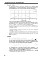
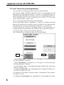
That is, on step 9 we will add an increment of 3 revolutions and 5556 counts, this
can be selected with a position select 0 PLC output digital output to change in this
case the parameters P1-17 and P1-18, using a digital; input on the servo drive.
There is no need to use MODBUS communications here with this control criteria,
even though this is other option.
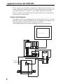
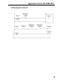
General control diagram
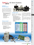
The control system can be comprised of the Sureservo drive, the PLC and the
accessories such as the thumbs pushbuttons (to acknowledge that the operators are
with the hands free), the home sensor, a proximity switch etc.
See the following diagram to see the relationship among the various devices.
Touch screen panel
PLC DL06
ZIP link
230 Volt, single phase
Rotary table
Home sensor
Operator’s
pushbuttons
servomotor
6
Servo Drive