1
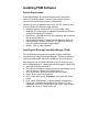
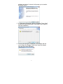
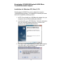
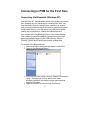
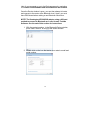
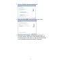
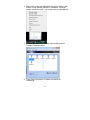
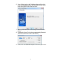
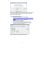
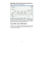
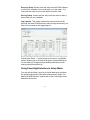
Getting Started With PowerSight For Bluetooth Meters Summit Technology, Inc. Walnut Creek, CA 94597 Tel: 1-925-944-1212 Fax: 1-925-944-7126 [email protected] www.powersight.com Rev 4 for All Meters / SW 3.4 Series Copyright 2013 by Summit Technology 1 PowerSight is a registered trademark of Summit Technology, Inc. All PowerSight models are designed to comply with part 15, subpart B, of the FCC Rules for a Class A digital device. PowerSight models PS2500, PS3500, and PS4500 are designed to comply with the requirements of IEC61010-1:2001 for a 600V input rating measurement category IV, pollution degree II, double insulated electronic device. PowerSight meters are manufactured by Summit Technology, Inc in the U.S.A. The standard warranty period is 12 months from date of purchase. We encourage you to advise us of any defects of design or manufacture of any of our products. We are dedicated to your successful use of the product. There are no user serviceable parts in your PowerSight meter. Opening the case voids your warranty and may result in present or future danger to users of the meter. The rechargeable battery inside is a custom-designed battery pack that is only to be replaced by authorized Summit Technology technical service personnel. Cleaning is to be done by use of a dry or damp piece of cloth. Grease may be removed by light application of isopropyl (rubbing) alcohol. Avoid the use of solvents, since they may dissolve or weaken the plastic enclosure. Do not use water or other conductive liquids since they may pose a safety risk. Use of this equipment in a manner not specified by Summit Technology can result in injury and voiding of warranty. 2 Table of Contents Introducing PowerSight .............................................................. 4 Installing PSM Software .............................................................. 5 System Requirements ......................................................................... 5 Installing and Running PowerSight Manager (PSM) ........................ 5 Installing Bluetooth Adapters ..................................................... 6 General ................................................................................................. 6 BU-2094a Bluetooth v2.0 USB Adapter (BLACK) ............................. 6 Widcomm Bluetooth Software ........................................................... 6 Installation for Windows XP ................................................... 6 Installation for Windows Vista & Windows 7 .......................... 8 BU-2073-J Bluetooth v2.0 USB Adapter (BLUE)............................. 10 Windows Default Bluetooth Software ............................................. 10 Installation for Windows XP ................................................. 10 Installation for Windows Vista & Windows 7 ........................ 11 Kensington K33902US Bluetooth USB Micro Toshiba Bluetooth Adapter ............................................................................................... 12 Installation for Windows XP, Vista, & 7/8 ............................. 12 Connecting to PSM for the First Time ..................................... 13 Connecting Via Bluetooth (Windows XP) ....................................... 13 Connecting Via Bluetooth (Windows Vista & Windows 7) ............ 15 Connecting Via Bluetooth (Windows XP, Vista & Windows 7/8) with the Kensington K330902US ..................................................... 18 Upgrading Software/Firmware Via PSM .................................. 22 Software and Meter Interface.................................................... 24 PSM Interface ..................................................................................... 24 Meter Interface ................................................................................... 25 Setting up PowerSight for Logging ......................................... 26 Using PSM to Setup PS2500 & PS3500 Meters .............................. 26 Using PSM to Setup PS4500 Meters ................................................ 28 Using PowerSight Interface to Setup Meter.................................... 31 Hooking Up Your PowerSight................................................... 32 Connections to PowerSight.............................................................. 32 Verifying Connections............................................................... 33 Using SureStart™ of PowerSight ...................................................... 33 Checking Connections Using PSM .................................................. 34 Checking Voltage/Current Levels – Using PSM ............................. 34 Starting/Stopping Your Monitoring Session ........................... 35 Downloading Data Using PSM .................................................. 36 Downloading Data Via Serial Connection ....................................... 36 Downloading Data Via Memory Card............................................... 37 Creating A Report Using PSM .................................................. 40 3 Introducing PowerSight Congratulations on your decision to buy one of our PowerSight meters! You have just purchased one of the smallest and yet most powerful instruments for measuring and analyzing electric power that exists. Each PowerSight meter is uniquely designed to help answer your power analysis questions like; what does it cost to run this equipment, to, what sort of transients appear on this line? The philosophy of the product is to give you an instrument that answers your questions about electric power in a truly convenient size at an attractive price. If you are looking for a simple yet powerful tool that can be easily and reliably installed and operated, one that provides for comprehensive data analysis, you've found your tool of first choice. Whether your interest is in The quality of incoming power, Managing power consumption, or Maintaining and comparing equipment PowerSight puts all the power in the palm of your hand! This guide will show you all the basics of using your PowerSight meter, from installing our simple-to-use PSM software, to hooking up your meter for the first time. *Note: Throughout this manual, whenever we refer to an individual key of the keypad, we print the name on the key enclosed by square brackets. For example, the “Volt” key is referred to as [VOLT]. 4 Installing PSM Software System Requirements PowerSight Manager is a powerful program that is designed to operate on modest systems. However, having certain system resources will dramatically improve its performance. Following is a list of capabilities required in your PC system in order to run the PSM 3.4 Series and newer software: Operating system: Windows ® XP or newer (when using Windows XP, system must be updated to the latest service pack and have Microsoft .NET installed). Disk Drives: CD-ROM disk drive (for installation) and a hard disk with at least 20 MB free. Serial Communications: Either an internal Bluetooth device for models PS2500, PS3500, & PS4500, or a USB connection for use with a USB-to-Bluetooth dongle/adapter. Display: VGA or better capability. Installing and Running PowerSight Manager (PSM) The CD-ROM that accompanies this guide contains all the files required to begin using PowerSight Manager. Following installation, refer to the Help system within it for answers to all your questions. Assuming that your CD-ROM is defined as drive D: and your hard disk is defined as drive C:, perform the following steps to install PSM: 1. Insert CD-ROM disk into drive D: 2. The software installation window should now automatically run on your computer. If it doesn’t start, follow steps 3-5. 3. Click on the "Start" button at the lower left of the screen 4. Select "Run" from the list of options. 5. In the "Open" box, type in “D:\autorun”, then press the “Enter” button. 6. Click “Install PSM Software” to begin installing the application. 7. Follow any instructions that appear on the screen. For easy installation, click on the “Next” button each time it stops to ask a question and click on “Finish” at the end. 5 To run PowerSight Manager in the future, select “Start” then guide your mouse from “Programs” to “PowerSight” to “PowerSight Manager” and click on “PowerSight Manager”. You can also double click on the PowerSight manager icon that is loaded on your desktop. Remember, the software on the disk is only licensed for use with your PowerSight meters. Installing Bluetooth Adapters General To communicate with the PS2500, PS3500, or PS4500, you will need a Bluetooth connection. Some computers have an internal Bluetooth device for communicating. If your PC/laptop is not Bluetooth compatible, you will need to use a USB-to-Bluetooth adapter or “Dongle”. Do not install the USB-to-Bluetooth adapter until later in the process. You may want to close all open windows on your PC since the computer will need to be restarted before the Bluetooth adapter can be used. Listed below is how to install the two different types of Bluetooth Dongles supplied with our rental meters for both Windows XP and Windows Vista/7: *Other devices may vary* BU-2094a Bluetooth v2.0 USB Adapter (BLACK) Widcomm Bluetooth Software Installation for Windows XP 1. NOTE: Do not install your USB Bluetooth adapter into your computer until you finish installing the software. 2. Insert the CD in your CD-ROM drive and let it run the installation. Follow the instruction from the CD-ROM 6 software and when it is done it will prompt you to install a Bluetooth device. 3. A “Welcome to Bluetooth” screen will appear. Press “Next”, accept the License Agreement, then press “Next” again to start the installation. 4. At one point during the installation, the software will ask you to plug in the dongle. At this time, insert the dongle into one of the free USB ports. 7 5. Click “Finish” and restart your computer. Installation for Windows Vista & Windows 7 The installation of the Bluetooth dongle is much different on a Windows Vista/7 computer than it is on Windows XP. 1. Insert the Bluetooth Dongle. Windows will then attempt to install its own Bluetooth drivers. 2. Once Windows is done, run the program SetupBtwDownloadSE.exe from either the PSM CD-ROM (found in the Summit Technology\software folder) or found at http://www.broadcom.com/support/bluetooth/update.php 8 3. Choose to “Run” the EXE file, accept the License Agreement, and click “Next”. 4. The Broadcom/Widcomm software should now be installing. 5. You may get a Windows security pop-up, click “Install”. 9 6. Click “Done” when the software is finished installing. You may need to restart your computer. BU-2073-J Bluetooth v2.0 USB Adapter (BLUE) Windows Default Bluetooth Software Installation for Windows XP The BU-2073-J does not include a CD-ROM, but instead relies on Windows to find the drivers from the web. To install this dongle, make sure your computer is connected to the internet and then plug in the dongle. Windows should then install the correct drivers. 1. Plug in the BU-2073-J Dongle. Windows should then give a pop-up window showing it has started installing the device. 10 2. Wait for Windows to finish. Once done, it will tell you the device is ready to be used. Installation for Windows Vista & Windows 7 Since the BU-2073-J Dongle does not come with a CD-ROM, insert the Bluetooth Dongle. Windows will then attempt to install its own Bluetooth drivers. Make sure your computer is connected to the internet so that windows can install the correct drivers. NOTE: This has not been tested with Windows 8. When finished installing the drivers, you should get the following screen: 11 Kensington K33902US Bluetooth USB Micro Toshiba Bluetooth Adapter Installation for Windows XP, Vista, & 7/8 The Kensington K33902US is a micro adapter that uses the Toshiba Bluetooth software. The installation is basically the same across all compatible operating systems. 1. NOTE: Do not install your USB Bluetooth adapter into your computer until you finish installing the software. 2. Insert the CD in your CD-ROM drive. Follow the instruction from the CD-ROM software and when it is done it will prompt you to install a Bluetooth device. 3. You may or may not get a prompt to restart your computer. Any either case, once installation is done, restart your computer with the adapter plugged in. 12 Connecting to PSM for the First Time Connecting Via Bluetooth (Windows XP) With Windows XP, each Bluetooth device will use the same comm port, meaning only one meter can be connected at a time. You must disconnect from one meter before connecting to another (this is done by either turning off the meter or disconnecting from the Bluetooth device). You also must have PSM closed before making any connections to a meter at the Bluetooth level. You will also find a “My Bluetooth Places” icon on the desktop. This is where you will first establish a connection to the meter before you actually connect to the PSM software. Only the PS2500, PS3500 and PS4500 can connect via Bluetooth. To connect at the Bluetooth level: 1. Make sure PSM is closed and the meter is turned ON. 2. Open up “My Bluetooth Places”. 3. At the top left of the screen, click on “Search for Devices in range”. It should now look for and find the meter, displaying a default icon with the meter type and serial number in its name. 4. Right click on this icon and choose ‘Pair Device”. 13 5. Choose to enter the device’s code and put in “0000” (four zeros) as the Bluetooth Pass Code and press “OK” 6. Once this in accepted, double click on the icon of your meter. It will now do a one-time attempt to discover available services, then it should display an icon that looks like a serial connector and says “not connected”. 7. Double click on this icon (or right click and choose “Connect to SPP”). 14 8. Once connected, it should give you the comm port number for your connection. 9. Open up PSM and click on the “Setup Communications” button. 10. Change the Comm Port to the one assigned by Bluetooth (baud rate should be 57600 for all meters). 11. Press “OK” and PSM will attempt to connect to your meter. NOTE: When using the BU-2073-J Dongle (BLUE), you may not get a “My Bluetooth Places” icon. If this is the case, follow the Windows Vista & Windows 7 instructions. Connecting Via Bluetooth (Windows Vista & Windows 7) With Windows Vista or Windows 7, you will not find a “My Bluetooth Places” icon on your computer. To connect, you have to either use the small Bluetooth icon that shows up at the bottom 15 right of your computer or go to the Devices screen by navigating to: Control Panel\Hardware and Sound\Devices and Printers. Once the Device window is open, you can then attempt to locate and connect to the meter at the Bluetooth level. Again, you must have PSM closed when making a new Bluetooth connection. NOTE: The Kensington K330902US adapter using a different method to connect to Bluetooth as it uses its own Toshiba Software. See the end of this section for instructions. 1. With the meter turned on, in the Bluetooth Device window, press “Add a Device” to bring up the search window. 2. Double click on the icon that states your meter’s model and serial number. 16 3. Click on “Enter the devices’ pairing code”. 4. Enter the code “0000” (four zeros) and press “Next” 5. Windows will now assign a comm port to this meter. To view this number, either click on the Windows pop-up at the bottom right of your screen, or right click on the meters’ icon in the devices window and press “Properties”. 17 6. Once the devices properties window pops up, click on the “Hardware” tab to view the serial port assigned to your meter. 7. Open up PSM and click on the “Setup Communications” button. 8. Change the Comm Port to the one assigned by Bluetooth (baud rate should be 57600 for all meters). 9. Press “OK” and PSM will attempt to connect to your meter. Connecting Via Bluetooth (Windows XP, Vista & Windows 7/8) with the Kensington K330902US The Kensington K330902US Micro Adapter using the Toshiba software to connect to Bluetooth. 18 1. Right Click on the small Bluetooth Icon at the bottom right corner of your desktop (Near the Time/Date). You may need to press the small ^ (up arrow) button on the task bar. 2. Click on “Bluetooth Setting” and it should bring up the Toshiba Software window. 3. Press “New Connection” to add a new meter for connecting. 19 4. Choose “Express Mode” and press “Next”. It will now search the area for Bluetooth devices. 5. Select the meter you want to connect to and press “Next”. It will then you’re your meter to your computer. You may have to enter a Security code, this code is “0000”. 20 6. Once finished pairing, the Toshiba software will give this meter a comm port number, this is the port you will select when using PSM. Press “Next” to finish. 7. Open up PSM and click on the “Setup Communications” button. 8. Change the Comm Port to the one assigned by Bluetooth (baud rate should be 57600 for all meters). 9. Press “OK” and PSM will attempt to connect to your meter. 21 Upgrading Software/Firmware Via PSM PSM version 3.48 and newer supports upgrading both PSM and the firmware in PS4500/3500/2500 meters via the web. By default, PSM is set to check for software updates every time it is opened and the computer is connected to the internet. It also checks if there is a newer firmware upgrade available each time the meter is connected. You can change how often automatic updates occur (or to disable them) by going to TOOLS->Check for Software/Firmware Updates. If an update is available, a pop-up should appear, showing what version is available. Press “Install” to upgrade. 22 NOTE: Do not upgrade Firmware unless you have downloaded all data and data setups needed from the meter as the meter will erase this data after upgrade. To manually upgrade the meter: 1. download the firmware file for your meter at http://www.powersight.com/downloads/index.cfm?list=Fir mware. 2. In PSM, connect to the meter and click on TOOLS->Firmware Upgrade. 3. Once the Firmware upgrade window pops up, press “Browse” and find the desired PSXXXX-XXX.s19 file, press open, then press “Upgrade”. NOTE: Upgrade time may take several minutes. 23 Software and Meter Interface Below is a brief description of the buttons on the PSM software and a few of our main buttons on the PowerSight meters. For more in-depth explanation of each button, please refer to the meters’ user manual that can be found on the CD-ROM. PSM Interface 1. Data Setup: change meter’s logging parameters. 2. Setup Unit: change greeting, synchronize time to PC, set billing rate. 24 3. Setup Communications: change communications port number and baud rate. 4. Receive Via Serial Comm: download data from meter via serial, Bluetooth. 5. Receive Via Memory Card: download data from memory card inserted into your PC. 6. View Data buttons: View data stored on your computer 7. Remote Control: Show the attached meter’s display and keypad on your computer monitor so that you can view and control your meter from the PC. 8. View Attached Signals: Capture and display the waveforms of the signals attached to the meter at that time. 9. Measurement Overview: View real-time measurements of voltage, current, and power readings from the connected meter. 10. Create a New ReportWriter Document: brings up the ReportWriter software for creating reports from data logs. Meter Interface 25 1. [VOLT], [CURRENT], [POWER], [ENERGY], [COST], [FREQ], [ON/OFF CYCLES], [POWER FACTOR], [DEMAND PERIOD], [HARMONICS], [TIME]: Used to show real-time measurements. Press repeatedly to cycle between showing each phase and all phases. 2. [MONITORING ON/OFF]: Start and stop data logs, frequency analysis (FAO option). 3. [VERIFY CONNECTIONS]: Uses the SureStartTM feature to determine if all the inputs are connected correctly. 4. [TRIGGERED EVENTS]: Used to show how many swells (PS4500), dips (PS4500), and transients (PS3500 & PS4500) occurred during testing. 5. [MORE…]: Displays secondary displays of many of the keys such as the maximum, the minimum, and the average. 6. [CAPTURE WAVEFORMS]: Stores a 50 msec (3 cycles) snapshot of voltages and currents connected to the meter. 7. [INPUT RATIOS]: used to setup input ratios and calibrate meter. 8. [MEASURE MODE]: Used to view voltage, frequency and power modes. 9. [SETUP]: Displays many of the operational settings available. 10. [ADMIN]: Displays the administration functions. Setting up PowerSight for Logging Using PSM to Setup PS2500 & PS3500 Meters This section is for setting up the following meter models: PS2500, PS3500. You must have the meter already connected to the PSM software in order to save the setup to the meter. 26 Below is the Data setup screen for the PS2500 & PS3500 models. Operation Setup: Settings for data log monitoring. 1. Logging Period: Sets how often the meter summarizes its measurements into memory. 2. Log Start & Stop Modes: Used to set how and when the meter starts and stops monitoring. 3. Input Frequency: Sets frequency mode. 4. Voltage Mode: sets phase-to-neutral or phase-to-phase modes. 5. Power Mode: For selecting different power modes. 6. Define Input Ratios and Names: For entering input ratios for each input for use on multiple conductor systems or to display primary measurements when hooked up on secondary of a CT or PT. Save Log Setup: Used to save the setup from the PSM software to either your computer (to be used later), or to the meter. You must save the setup to your meter before it can be used. Get Log Setup: Used to pull the setup from the meter or from a saved setup on your computer. 27 Log Capacity: This section shows how many records can be stored in the meter’s RAM memory and how long the memory will take to fill up based on the logging period. Pressing the “Choose Measurement Types…” button brings up the above “Log Details” screen, allowing you to choose what types of measurements go into the data log. Changing these variables effects how much memory each record takes up. Using PSM to Setup PS4500 Meters This section is for setting up the following meter models: PS4500. You must have the meter already connected to PSM in order to save the setup to the meter. 28 Below is the Data setup screen for the PS4500 model. Monitoring Activities: Used to allocate the meter’s memory for logging. Changing the amount of records/waveforms/graphs effects how much memory is used. The “Reallocate Memory” button shows how much each logging type will take up in the RAM memory. 1. Log of Consumption: Basic data logging function. This logs the voltage, current, power, power factor, etc. 2. Consumption Wavesets: Allocates waveform sets used by the [CAPTURE WAVEFORMS] key. 3. Swell/Dip Log: Allocates how many events the meter can save. 4. Swell/Dip RMS Graph: Allocates how many RMS half cycle readings the meter can save. 5. Swell/Dip Waveforms: Allocates how many events can also be captured by waveform. 6. Log Transients: Allocates how many transient events the meter can save. 7. Transient Waveforms: Allocates how many transient events can also be captured by waveform. 29 Triggering for Swells, Dips, Transients: Used to select which channels the meter will look for these events on. You may only want to look for voltage events, or events on all channels. NOTE: Capture Mode is not used at this time. Trigger Thresholds: This is where you set the thresholds the PowerSight meter will use when looking for events. 1. Voltage/Current Swells: RMS voltage or current used to determine what is considered a Swell. Set this value ABOVE your normal RMS measurements. 2. Voltage/Current Dips: RMS voltage or current used to determine what is considered a Dip. Set this value BELOW your normal RMS measurements. 3. Voltage/Current Absolute Trans: Instantaneous voltage or current peak. This is where any point of the signal (positive or negative) goes well above the threshold and triggers the event. Must be set ABOVE your normal peak signal, NOT RMS measurement. (For ex: a normal 120v signal as a peak of +/-169v, your threshold must be above 169V) 4. Voltage/Current Relative Trans: size of just the spike riding on the signal (what’s left when the underlying periodic waveform is removed). NOTE: The small buttons to the left of the thresholds for Absolute and Relative Trans is used to calculate default settings, based on a given normal RMS measurement. Operation Setup: Settings for data log monitoring. 1. Logging Period: Sets how often the meter summarizes its measurements into memory. 2. Log Start & Stop Modes: Used to set how and when the meter starts and stops monitoring. 3. Input Frequency: Sets frequency mode. 4. Voltage Mode: sets phase-to-neutral or phase-to-phase modes. 5. Power Mode: For selecting different power modes. 6. Define Input Ratios and Names: setting input ratios for each input for use on multiple conductor systems or to display primary measurements when hooked up on secondary of a CT or PT. 30 Save Log Setup: Used to save the setup from the PSM software to either your computer (to be used later), or to the meter. You must save the setup to your meter before it can be used. Get Log Setup: Used to pull the setup from the meter or from a saved setup on your computer. Log Capacity: This section shows how many records can be stored in the meter’s RAM memory and how long the memory will take to fill up based on the logging period. Pressing the “Detail…” button brings up the above “Log Details” screen, allowing you to choose what types of measurements go into the data log. Changing these variables effects how much memory each record takes up. Using PowerSight Interface to Setup Meter You can use the Meter’s keys to do limited data setup functions, like setting logging period and other measurement modes. For details on these functions, please refer to the PowerSight User’s Manual for that meter. 31 Hooking Up Your PowerSight Connections to PowerSight Voltage test leads plug into the top end of PowerSight. Each test lead of the Deluxe Voltage Test Lead set is labeled (VN, V1, V2, or V3) and each jack is similarly labeled (VN, V1, V2, or V3). VN should not be connected to ground if no neutral is present unless ground and neutral are the same connection. Note: The VN test lead is a different color from the other leads (black). Similarly, the VN jack on PowerSight is a different color from the other ones (black). Connecting anything other than neutral or ground to the VN jack can jeopardize your safety, the functioning of the unit, and the accuracy of the unit. Current probes plug into the top end of PowerSight, just above the voltage inputs. Each current probe is labeled (I1, I2, I3, or IN) and each jack is similarly labeled (I1, I2, I3, or IN). When plugging a current probe into PowerSight, the flat side of the plug should be facing upwards so the label is readable. This will align it properly for plugging into the PowerSight case. Clamp-on probes have a correct orientation in which to attach them. On most probes' head, there will be an arrow pointing in the direction of the conductor being measured. When clamped onto I1, I2, I3, or IN, the arrow should point along the conductor from the power source towards the load. If the current probe is connected backwards, its waveform will appear upside-down when you upload waveforms, it may be slightly less accurate in its current readings, and, most importantly, if you operate in positive/negative power measurement mode, power readings will be disastrously wrong. 32 Verifying Connections There are two methods that you can use to check to see if all your voltage and current probe connections are on correctly: 1. Use the “Verify Connection” (SureStartTM) feature on the PS2500, PS3500 and PS4500 meters. 2. Capture a waveform and use PSM to analyze each phase. Checking out your connections is important because wrong connection can ruin your monitoring, causing you to have to redo testing after connecting correctly. For more detailed information about what problems you may find connecting incorrectly and how PSM and the SureStartTM feature can help, please refer to the PowerSight User’s Manual for that meter. Using SureStart™ of PowerSight To use the SureStartTM feature on compatible meters, press the [VERIFY CONNECTIONS] key on the top row of the keypad (the PS2500 does not have a keypad, but the SureStartTM feature automatically starts when the meter first turned on). The SureStartTM feature briefly reports its findings in four groups of information. Press the [MORE] key to view the results (Press the [NEXT] key on the PS2500 meters). The results are shown in the following manner: Identify System – after analyzing all the voltage and current inputs, PowerSight identifies what type of system is connected. Error Summary – after analyzing connections, the number of possible errors detected is displayed, appearing for one second, each 6 seconds. 33 Identify Errors – If errors were detected, pressing the [MORE] key will result in each error being identified on the display. Press the [MORE] key repeatedly to advance through the list of errors. Provide Error Diagnostic Information – for each error message that is displayed, the background measurements that indicate the error are displayed once each 6 seconds. Once you have proceeded through this sequence of identifying the system and possible errors and have corrected the problems, you can proceed knowing that the power wiring and PowerSight’s connections to it are probably correct. Checking Connections Using PSM The PowerSight Manager (PSM) software can be used to visually determine if the system connections and levels are correct. You can use PSM to analyze the connections to the meter by either capturing a waveform on the meter and downloading it with PSM, or by connecting to PSM and using the “View Attached Signals” feature. Checking Voltage/Current Levels – Using PSM Once you have downloaded a waveform using PSM, open it and then a dialogue box opens asking you to choose what signals to view. Make your primary choice “Voltage”, and your secondary choice “Set All”. Next click on “View”. Verify that the voltage measurements are in the correct voltage mode, read the correct measurements, and are in the correct phase sequence. 34 While still viewing all voltage waveforms of a three-phase system, notice in what order they reach their peak value. Normally, the order should be 1-2-3. In other words the highest level of the V1N (or V12) waveform will be followed next by the highest level of the V2N (or V23) waveform, which will be followed by the highest level of the V3N (or V31) waveform (see the example). Next click on the blue “Back Arrow” icon and select “Current”, “Set All”, and “View”. Verify that the current measurement are what you expect and are in the correct phase sequence (should be the same sequence as voltage) Last, click on the blue back arrow again and select “Voltage and Current”. Here you can view the relationship of current to voltage and make sure each current phase is properly lined up with the correct voltage phase. If you notice any issues, make your changes and then take another waveform. Do not start your monitoring session unit you are comfortable with your connections. Starting/Stopping Your Monitoring Session There are multiple ways to initiate data logging on a PowerSight meter. Each meter can be setup to start logging at a certain time, started from the PSM software (through either the Remote Control or via the Data Setup), or started from the meter’s interface. To start logging at a certain time, refer to the “Log Start Mode” in the data setup. To initiate data logging on a PowerSight Meter: 35 1. PS2500: Press the [NEXT] key until a message on the display says “Hold Down Button to Start Logging”, hold the [NEXT] key for 2 seconds and the meter should start logging. 2. All Other Meters: Press the [MONITORING ON/OFF] key and follow the instructions on the display. To stop logging, either press the [NEXT] key (PS2500) or the [MONITORING ON/OFF] key PS3500 & PS4500) and follow its instructions. You can also turn off the meter to stop logging, but beware that the meter may be in the middle of taking a record and you may lose this record once power is lost. Downloading Data Using PSM Once logging is completed, there are two ways to download data 1. Downloading the data through the serial connection 2. Downloading the data from an SD card (if compatible) Downloading Data Via Serial Connection 1. Connect the meter to PSM through Bluetooth. 2. Once connected, Press the “Receive Via Serial Comm” button to bring up the receive data window. 3. Create a unique name in the File Name box (make sure to use only valid Windows characters). 36 4. Check the boxes next to each data type you want to download or click “Select All” to select all available data types (only available data types in the meter will show up in this window). 5. Press either the “Receive & View” button (downloads from the meter and then opens the first file checked) or the “Receive Only” button (downloads the data but does not open it). Once downloaded, you can then analyze your findings, print out graphs and create reports using the ReportWriter software. Downloading Data Via Memory Card With the PS2500, PS3500 or PS4500 meters, they have the capability of saving data to a SD card. Once logging has stopped, all data is transferred to the memory card (if it had not already during logging) . At this point, you can remove the card from the meter, plug it into your computer and use PSM to convert the SD card data into readable data files. To download/convert data from a SD card: 1. Make sure the meter is has stopped logging. 2. Remove the card and insert it into your computer. 3. Open up PSM (you do not need your meter connected to download data from the card). 37 4. Press the “Receive Via Memory Card” button to bring up the receive memory card files window. 5. Check the box of the directory in which you memory card (or memory card files) are stored in. 6. Click on the folder with your meter’s serial number, you should then see 1 or more folders named by time & date in the format of “YrMoDy_HrMnSc”. These names are based on when the data inside was first started/created. For example, if you data log started on 10/13/2011 at 2:01:25 pm, you would have a folder with the name; “111013_140125”. 7. Check the box or boxes of the file types you want to convert to readable PowerSight Files. These files are: a. $LO for Data Log (*.log) files b. $WF for Waveform (*.wfm) files c. $SL for Swell/Dip Log (*.slg) files d. $RL for RMS Graph Log (*.rlg) files e. $TL for Transient Log (*.tlg) files f. $SW for Swell/Dip Waveforms (*.swm) files g. $TW for Transient Waveforms (*.twm) files h. $PF for Frequency Analysis (*.pfd) files 38 8. Choose an Output Folder for the location on where you want the final files stored (by default they are stored in your C:\Program Files\Powersight folder) 9. Type in a unique file name (by default, the name “PSM” is used) into the Final File Name box and click “Receive Only”. A folder with your files should pop up when they are done converting. NOTE: multiple waveforms, swell/dip waveforms and transient waveforms are stored in the same “$” file, then extracted into multiple files with numbers appended to them. 39 Creating A Report Using PSM Once the data log has been downloaded, you can use the ReportWriter software to create a summary or comparison report. These reports take the data from the log and create a formatted report with numbers and graphs in a document-type program. Once created, you can save your report and open it up in a program like Microsoft Word and add to it. To create a report: 1. Open up the ReportWriter software. 2. Fill in the report information window and press “Next”. 3. Select either “Summary” or “Comparison” report and press “Next”. 4. Click “Browse…” and open the data log file you want to use for the report. The Starting/Ending Time is based on 40 the start and end of the data log chosen. Press “Next” when done. 5. In the Log Details window, select which variables you want to see in your report, select if you what half page graphs (2 graphs per page), full page graphs or no graphs and click “Finished”. 6. The ReportWriter will now take your information and create a report. You can then save the file to either a .txt format or a .doc format. 41