1
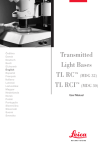
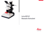
Leica MZ10 F
User Manual
General Notes
Safety concept
Before using your microscope for the first time,
please read the "Safety concept" brochure
included with your instrument. It contains
additional information about handling and
care.
Use in clean rooms
The Leica M series can be used in clean rooms
without any problems.
Cleaning
▶▶ Do not use any unsuitable cleaning agents,
chemicals or techniques for cleaning.
▶▶ Never use chemicals to clean colored
surfaces or accessories with rubberized
parts. This could damage the surfaces, and
specimens could be contaminated by abraded particles.
Servicing
▶▶ Repairs may only be carried out by Leica
Microsystems-trained service technicians.
Only original Leica Microsystems spare
parts may be used.
Responsibilities of person in charge of
instrument
▶▶ Ensure that the Leica stereomicroscope
is operated, maintained and repaired by
authorized and trained personnel only.
▶▶ In most cases, we can provide special solutions on request. Some products can be
modified, and we can offer other accessories for use in clean rooms.
Leica MZ10 F
User Manual
2
Important Safety Notes
User Manual
The individual modules of the Leica M stereomicroscopy series include an interactive
CD-ROM with all relevant user manuals in 20
other languages. Keep it in a safe place, and
readily accessible to the user. User manuals and
updates are also available for you to download
and print from our web site www.leica-microsystems.com.
This User Manual describes the special functions of the individual modules of the Leica
MZ10 F fluorescence stereomicroscope and
the Leica fluorescence module for the Leica M
stereomicroscopy series and contains important instructions for their operational safety,
maintenance, and accessories.
You can combine individual system articles
with articles from external suppliers (e.g. cold
light sources, etc.). Please read the user manual
and the safety requirements of the supplier.
Before installing, operating or using the instruments, read the user manuals listed above. In
particular, please observe all safety instructions.
To maintain the unit in its original condition
and to ensure safe operation, the user must
follow the instructions and warnings contained
in these user manuals.
Special manuals
Special manuals are provided for a number of
accessories:
▶▶ User Manual M2-216-1 for lamp housing
with high-pressure mercury burner.
▶▶ User Manual for ebq 100 isolated supply
unit for 100W high-pressure mercury
burners.
▶▶ User Manual M2-267-1 for the motorized
focus system.
The "Safety concept" booklet contains additional
safety information regarding the service work,
requirements and the handling of the stereomicroscope, accessories and electrical accessories
as well as general safety instructions.
Leica MZ10 F
User Manual
3
Symbols Used
Warning! Safety hazard!
This symbol indicates especially important information that must be read and
complied with.
• Failure to comply can cause the following:
▶▶ Hazards to personnel
▶▶ Functional disturbances or damaged instruments
Danger due to hot surface
This symbol warns against touching
accessible hot surfaces, e.g. those of
light bulbs.
Important information
This symbol indicates additional information or explanations that are intended
to provide clarity.
Warning of hazardous electrical voltage
This symbol indicates especially important information that is mandatory to
read and observe.
Explanatory notes
▶▶ This symbol within the text stands for additional information and explanations.
Failure to comply can cause the following:
▶▶ Hazards to personnel
▶▶ Functional disturbances or damaged instruments
Figures
(1) Numbers in parentheses within the
descriptions relate to the figures and the
items within those figures.
Leica MZ10 F
User Manual
4
Safety Instructions
Description
The individual modules fulfill the highest requirements for observation and documentation
with the Leica fluorescence stereomicroscopes.
Unauthorized alterations to the instrument or
noncompliant use shall void all rights to any
warranty claims.
Intended use
▶▶ Refer to "Safety Concept" booklet
Place of use
▶▶ Refer to "Safety Concept" booklet
Non-intended use
▶▶ Refer to "Safety Concept" booklet
▶▶ Electrical components must be placed at
least 10 cm away from the wall and from
flammable substances.
Never use fluorescence stereomicroscopes or
their components for surgical procedures (e.g.
on the eye) unless they are specifically intended
for that purpose.
▶▶ Avoid large temperature fluctuations,
direct sunlight and vibrations. These conditions can distort measurements and micrographic images.
The instruments and accessories described in
this User Manual have been tested for safety
and potential hazards. The responsible Leica
affiliate must be consulted whenever the instrument is altered, modified or used in conjunction with non-Leica components that are
outside of the scope of this manual!
▶▶ In warm and warm-damp climatic zones,
the individual components require special
care in order to prevent the build-up of
fungus.
Leica MZ10 F
User Manual
Responsibilities of person in charge of
instrument
▶▶ Refer to "Safety Concept" booklet
Ensure that:
▶▶ The M series stereomicroscopes and
accessories are operated, maintained and
repaired by authorized and trained personnel only.
▶▶ All operators have read, understood and
observe this User Manual, and particularly
the safety instructions.
5
Safety Instructions (continued)
Repairs, service work
▶▶ Refer to "Safety Concept" booklet
▶▶ Only original Leica Microsystems spare
parts may be used.
Integration in third-party products
▶▶ Refer to "Safety Concept" booklet
▶▶ Optimal arrangement of workplace, work
assignments and work flow (changing tasks
frequently).
Disposal
▶▶ Refer to "Safety Concept" booklet
▶▶ Thorough training of the personnel, giving
consideration to ergonomic and organizational aspects.
Legal regulations
▶▶ Refer to "Safety Concept" booklet
▶▶ The ergonomic optical design and construction of the Leica M stereomicroscopy
series are intended to reduce the exertion
of the user to a minimum.
▶▶ Before opening the instruments, switch off
the power and unplug the power cable.
Touching the live circuit can cause
injury.
Transport
▶▶ Use the original packaging for shipping or
transporting the individual modules of the
Leica M stereomicroscopy series and the
accessory components.
▶▶ In order to prevent damage from vibrations,
disassemble all moving parts that (according to the user manual) can be assembled
and disassembled by the customer and
pack them separately.
Leica MZ10 F
EC Declaration of Conformity
▶▶ Refer to "Safety Concept" booklet
Health risks
Workplaces with stereomicroscopes facilitate and improve the viewing task, but
they also impose high demands on the eyes
and holding muscles of the user. Depending on
the duration of uninterrupted work, asthenopia
and musculoskeletal problems may occur. For
this reason, appropriate measures for reduction
of the workload must be taken:
• User Manual
6
Safety Instructions (continued)
• transmission method for bacterial and viral
Direct contact with eyepieces is a potential
infections of the eye.
The risk can be kept to a minimum by using
personal eyepieces for each individual or
detachable eyecups.
Leica MZ10 F
Light sources: Safety instructions
Protective measures of the manufacturer:
▶▶ UV protection screen in front of the specimen plane prevents the user from looking
directly into the UV rays.
▶▶ Dummy filter carriers in the free positions
of the rapid filter changer prevent direct UV
radiation from reaching the eyes.
Warning
UV radiation could damage the eyes. Therefore:
• ▶▶ Never look into the light spot on the specimen plane without a UV protection screen.
▶▶ Never look into the eyepieces if no excitation filter is in the beam path.
▶▶ UV filters are installed in the observation
beam paths to protect the eyes.
▶▶ Fill empty filter positions with dummy filter
carriers.
▶▶ The stray-light protection on the lamp
housing prevents irradiation of the hands.
▶▶ Do not select a white, strongly reflective
background for the specimen.
User Manual
7
Safety Instructions (continued)
Supply unit
Always unplug the supply unit from the power
supply:
▶▶ When installing and disassembling the
lamp housing
▶▶ Before opening the lamp housing
▶▶ When replacing the high-pressure mercury
lamp and other parts, such as the heatabsorbing filter or the collector
Lamp housing
Never open the lamp housing while the
lamp is switched on. Risk of explosion, UV
exposure, blinding!
• • to cool off for at least 15 minutes. Danger
Before opening the lamp housing, allow it
of explosion!
• housing. Fire hazard!
Never cover the air duct on the lamp
▶▶ During maintenance work on the supply
unit
Mercury lamp
▶▶ Follow the user manual and safety instructions provided by the lamp manufacturer, and, in particular, the section on how
to proceed if a lamp breaks and releases
mercury.
▶▶ For transport, remove the mercury lamp,
transport it in its original packaging and
protect moving parts in the lamp housing
using the transport anchors.
▶▶ When it has reached the end of its rated life
(follow the manufacturer's specifications
and the minute meter on the supply unit).
▶▶ To minimize the risk of explosion, replace a
discolored mercury lamp promptly.
▶▶ Leica Microsystems assumes no liability
for damage caused by exploding, incorrectly installed or improperly used mercury
lamps.
Leica MZ10 F
User Manual
8
Table of Contents
Assembly
Assembling the Focusing Column with a Transmitted Light Base
16
Assembling the Focusing Column with an Incident Light Base
17
Motorized Focus: Restricting the Travel Path
18
Optics carrier
19
Iris Diaphragm
20
Tube21
Eyepieces22
Objective23
UV Protection Screen: Assembly
24
Transmitted Light Base TL ST
25
Transmitted Light Base TL BFDF: Before First Use
26
Transmitted Light Base TL BFDF
27
TL RC™ / TL RCI™
28
IsoPro™ Manual Mechanical Stage: Assembly
29
Leica IsoPro™ Motorized Mechanical Stage: Assembly
31
Leica EL6000 – Safety Notes
35
Leica EL6000 – Preparations
38
Leica EL6000 – Connection to the Fluorescence Lamp Housing
41
Leica MZ10 F
Quick Start Guide
An Overview of the Leica MZ10 F
44
The Correct Interpupillary Distance
45
Using the Eyepieces
46
Focusing47
Adjusting the Resistance of the Focus Drive
48
Changing Magnification (Zoom)
49
Double Iris Diaphragm
50
Ratchet Steps and Magnification Levels
51
Parfocality: More Comfort and Convenience for Your Work
52
Eyepieces
Magnification Factors of the Eyepieces
Health Notes
Dioptric Correction
Dioptric Correction and Parfocality
Graticules
54
55
56
57
58
Photography & Video
Photography & Video
Photo Tubes and C-mounts
Trinocular Video/Phototube 50%
Trinocular Video/Phototube 100%
60
61
62
63
User Manual
9
Optics Accessories
The Different Types of Objectives
65
Bases
Leica TL ST Transmitted Light Base: Controls
Leica TL ST Transmitted Light Base: Operation
Leica TL ST Transmitted Light Base: Changing bulbs
Leica TL BFDF Transmitted Light Base: Controls
Leica TL BFDF Transmitted Light Base: Operation
Leica TL RC™ / TL RCI™: Controls
Leica TL RCI™: The Path-folding Mirror
Leica TL RCI™: Color Intensity and Temperature
Leica TL RC™ / TL RCI™: Operation
Leica TL RCI™: Methods in Transmitted Light
Leica TL RCI™: Relief Images
Using Filters
Leica IsoPro™ (Non-motorized): Controls
Leica IsoPro™ (Motorized): Controls
67
68
69
70
71
72
73
74
75
76
77
79
80
81
System Illumination Leica EL6000
Leica EL6000 – About the Instrument
Leica EL6000 – Operation
Leica EL6000 – Troubleshooting
Leica EL6000 – Cleaning and Maintenance
Leica EL6000 – Replacing the Lamp
83
85
86
87
88
Leica MZ10 F
Fluorescence
Filter Changer
About Fluorescence Microscopy
Simple Filter Holders
Equipping the Filter Changer
Observation without Fluorescence
Commissioning the Fluorescence System
90
91
92
93
94
95
Dimensional Drawings
MATS TL
97
Specifications
Leica MZ10 F – Specifications
Leica EL6000 – Specifications
Leica TL ST Transmitted Light Base
Leica TL BFDF Transmitted Light Base
Leica TL RC™ / TL RCI™
99
100
102
103
104
Appendix
Calculating the Total Magnification/Field of View Diameter
Care, Maintenance, Contact Persons
106
107
User Manual
10
Leica MZ10 F
Leica MZ10 F
User Manual
11
Congratulations!
Congratulations on obtaining your new Leica MZ10 F stereomicroscope.
We are convinced it will fully meet your expectations, as never before have
we applied our decades of experience in the areas of optics, mechanical
engineering and ergonomics in such an uncompromising manner.
The Leica MZ10 F embodies all the qualities you associate with the name
Leica Microsystems: excellent objectives, high-quality engineering, and
reliability. Furthermore, the modular design ensures that the Leica MZ10 F
adapts perfectly to your needs—no matter which accessories you require
for your tasks.
Though the reliability and robustness of Leica stereomicroscopes is worldrenowned, the Leica MZ10 F requires a certain degree of care and attention. Therefore, we recommend that you read this manual. It contains all
the information you need regarding operation, safety and maintenance.
Simply observing a few guidelines will ensure that even after years of
intensive use, your stereomicroscope will continue to work as smoothly
and reliably as on the very first day.
We wish you the best of success in your work— after all, you are now
equipped with the best tool!
The entire imaging system, including the zoom, objective and ErgoTube®, is
apochromatically corrected with much technological effort. Contrast, sharpness, richness in detail, resolution, image and color fidelity are optimum. In
addition, the patented illumination beam path guarantees at every zoom
level that light utilization is at a maximum and that fluorescence images
are intensely luminous on a jet black background.
Leica MZ10 F
User Manual
12
The Modular Design: Everything is Relative
The Leica M series provides maximum flexibility
in choosing equipment, thanks primarily to the
modular configuration and the compatibility
that Leica has painstakingly maintained for
decades. The optics carriers, eyepieces, bases
and more can be combined in any way you
choose, allowing you to create the microscope
that best suits your needs.
Leica MZ10 F
Despite this, you will notice that the control
elements and individual components do not
differ significantly. Whichever configuration
you choose, you will quickly feel right at home.
User Manual
Have a special request? Let us know!
Leica Microsystems enjoys an exceptional reputation when it comes to devising customerspecific solutions. If you have a special request
that cannot be met with standard parts, contact
your Leica consultant. We have a solution for
every problem.
13
On We Go
If your new Leica microscope has already been
assembled and commissioned by your Leica
consultant, click here to skip through the installation instructions and go directly to the Quick
Start Guide on Page 43.
Leica MZ10 F
If, on the other hand, you are assembling the
microscope yourself, continue with the "Assembly" chapter, which begins on Page 15.
User Manual
For everything you need to know about the
correct use of fluorescence-related parts, refer to
Page 89.
14
Assembly
Leica MZ10 F
User Manual
15
Assembling the Focusing Column with a Transmitted Light Base
The first step is to connect the focusing column
of the M series to the corresponding base.
Assembling the column adapter
1. Securely install the column adapter on the
column using the four included screws.
Assembling the focusing column
2. Securely screw the focusing column to the
base using the six included screws.
Tools used
▶▶ Hex socket screwdriver, 3 mm
Leica MZ10 F
User Manual
16
Assembling the Focusing Column with an Incident Light Base
When using an incident light base, the focusing column and motorized focus are installed
directly on the base; no extension plate is required.
Assembly
1. Place the focusing column on the side.
3. Screw the base securely onto the focusing
drive.
Tools used
▶▶ Hex socket screwdriver, 3 mm
2. Insert the four screws provided into the
outer holes of the base.
Leica MZ10 F
User Manual
17
Motorized Focus: Restricting the Travel Path
may be necessary to restrict the maxiDepending on the work situation, it
mum travel path of the stereomicroscope. This
prevents the following:
▶▶ Injuries when manipulating the specimen
because the fingers or hand get pinched.
Restricting the bottom travel range
1. Move the motorized focus into the lowest
position you want to reach.
2. Unscrew the screw of the limit stop on the
side of the focusing column.
3. Push the limit stop to the height of the
motorized focus.
It is easiest to move the limit stop by keeping the
screwdriver inserted and moving it upwards.
4. Tighten the screw of the limit stop.
▶▶ Accidental contact between the objective
and the specimen, and potential resulting
damage.
Readjusting the motorized focus
The motorized focus is factory-adjusted and
normally does not need to be readjusted—
even if the maximum travel path is changed.
• rized focus is moving, the position data
Exception: If the power fails while the moto-
are lost. In this case, the calibration must be
repeated using the Leica LAS software or the
Leica SmartTouch™. To do so, please consult the
respective manual.
Leica MZ10 F
User Manual
18
Optics Carrier
Tools used
▶▶ Hex socket screwdriver, 4 mm
tives of the M series (article numbers 10
Please use the planapochromatic objec-
Assembling the Optics Carrier
1. Place the microscope carrier on the focusing column so that the screw fits into the
thread provided and the lug fits into the
groove.
450 027 to 10 450 030) with the microscope
carrier. If you have any inquiries regarding
compatibility and adaptation of other models,
please contact your Leica consultant.
3. Insert the optics carrier into the microscope
carrier and fasten it with the locking screw.
2. Press the microscope carrier backwards to
the focusing column and screw it in place
using your other hand.
Leica MZ10 F
User Manual
19
Iris Diaphragm
be attached between the optics carrier
The optional iris diaphragm, which can
and tube, fulfills the same purpose as those in
a camera: It regulates the available light, which
changes the depth of field. The "depth of field"
(or "depth of focus") is the area of a specimen
that is brought into sharp focus.
Leica MZ10 F
Installing the iris diaphragm
1. Place the iris diaphragm on the optics
carrier and tighten the locking screw.
User Manual
20
Tube
the optics carrier and the binocular tube
All intermediate tubes that fit between
are fitted in the same manner.
ate elements can lead to shading in the
Please note that inserting intermedi-
Assembling the tube
2. Push the tube (for example, the inclined
binocular tube) into the dovetail ring and
rotate it slightly in both directions until the
positioning screw meshes with the guide
groove.
3. While holding the tube only slightly, carefully tighten the positioning screw. It is
automatically brought to the correct position.
border area of the field of view.
Preparations
1. Unscrew the positioning screw and remove
the protective cover.
Leica MZ10 F
User Manual
21
Eyepieces
Tools used
▶▶ No tools required.
Magnification range
You can extend the overall magnification range
using available 10×, 16×, 25× and 40× widefield eyepieces for persons wearing glasses.
Preparation
1. If you want to use an optional graticule,
insert it now (Page 58).
Inserting the eyepieces
3. Push the eyepieces into the tubes as far as
they will go and check to ensure that they
fit tightly and accurately.
2. Remove the plastic tube guard.
4. Securely tighten the clamping screws.
Leica MZ10 F
User Manual
22
Objective
Tools used
▶▶ No tools required.
Attaching the objective
1. Remove the protective cover on the optics
carrier.
2. Screw the objective clockwise into the
optics carrier.
• and disassembly so that it does not fall onto
Hold the objective firmly during assembly
the stage plate. This applies particularly to the
2x planapochromatic objective, which is very
heavy. Remove all specimens from the stage
plate first.
Leica MZ10 F
User Manual
23
UV Protection Screen: Assembly
Tools used
▶▶ Allen key
Assembly
1. Screw the adapter for holding the UV
protection screen to the fluorescence axis.
Intended use
The UV protection screen in front of the specimen plane prevents the user from looking
directly into the UV rays.
2. Fasten one side of the holder for the UV
protection screen on the adapter. The other
side holds the protection screen.
3. Bring the holder into the correct position
by turning it on its center joint. Tighten the
screw on the center joint to fasten the UV
protection screen in the selected position
in front of the objective.
Safety Notes
UV radiation can damage the eyes. Therefore, it is mandatory to install the UV filter
and adjust it correctly.
• • that the operator can never look directly at
Always position the UV protection screen so
the light spot.
Leica MZ10 F
User Manual
24
Transmitted Light Base TL ST
Unpacking the base
The base is delivered with the adapter plate
installed. Make sure the instruments are unpacked on a flat, sufficiently dimensioned, and
non-slip surface.
Leica MZ10 F
Focusing drive and column
1. Unscrew the extension plate from the base
using the Allen key provided.
2. Attach your focusing drive column from
below using the four hexagon-head screws.
3. Reattach the adapter plate to its original position using the six hexagon-head
screws.
User Manual
25
Transmitted Light Base TL BFDF: Before First Use
Removing the transport anchors
Before you can use the transmitted light
base for the first time, it is absolutely necessary to remove the two transport anchors.
• Anchor of mirror
Anchor of switching slide
Leica MZ10 F
User Manual
26
Transmitted Light Base TL BFDF
Standard delivery
The base is delivered with the adapter plate
installed. The selected stage (Leica IsoPro™
Cross-stage or Leica standard stage 10 447 269),
and the focusing drive will have to be mounted
later.
Stage assembly
The Leica TL BFDF transmitted light base can be
equipped with three different stages.
The selected stage is mounted on the base
before commissioning. You can switch between
the stages at any time with just a few hand
movements.
The following paragraph assumes use of the
base without the stage mounted. Disassembly
is performed in reverse order of the following
steps.
▶▶ Leica IsoPro™ Manual Cross-stage
▶▶ Leica IsoPro™ Automatic Cross-stage
▶▶ Leica standard stage 10 447 269
Leica MZ10 F
Standard stage
1. Take the glass plate from the rectangular
gap in the standard stage.
2. Position the stage on the transmitted light
base in such way that the four holes align
over those in the base.
3. Attach the stage to the base with the four
supplied hexagon-head screws.
4. Insert the glass plate back into the standard
stage.
User Manual
27
TL RC™ / TL RCI™
The base is delivered with the adapter plate
installed. The selected stage (Leica IsoPro™
Cross-stage or Leica standard stage 10 447 269)
and the focusing drive will have to be mounted
later.
Ensure that the instruments are unpacked
on a level, adequately sized, and nonskid
underlay.
Stage assembly
The Leica TL RC™/ RCI™ transmitted light base
can be equipped with three different Leica
stages. The selected stage is mounted on the
base before commissioning. You can switch
between the stages at any time with just a few
hand movements.
Standard stage
1. Take the glass plate from the rectangular
gap in the standard stage.
2. Position the stage on the transmitted light
base in such way that the four holes align
over those in the base.
3. Attach the stage to the base with the four
supplied hexagon-head screws.
4. Insert the glass plate back into the standard
stage.
The following paragraph assumes use of the
base without the stage mounted. Disassembly
is performed in reverse order of the following
steps.
Leica MZ10 F
User Manual
28
IsoPro™ Manual Mechanical Stage: Assembly
Leica IsoPro™ Cross-stage
Before the Leica IsoPro™ Cross-stage is mounted to the base, the axis containing the control
buttons is attached either on the left or the
right side of the cross-stage.
Left or right operation
If the controls are to be mounted on the lefthand side, the gear rod on the bottom side of
the cross-stage must be unscrewed and reattached in reverse.
Assembly
1. Take the glass plate from the mechanical
stage.
2. Turn the mechanical stage around and
place it onto a non-slip surface.
3. Change the gear rod from the left to the
right-hand side.
over the first three items of the following
The install the operating elements, skip
description.
Leica MZ10 F
User Manual
29
Leica IsoPro™ Manual Mechanical Stage: Assembly (cont'd.)
Control assembly
1. Take the glass plate from the mechanical
stage and turn it around.
2. Attach the axis with the control buttons to
the desired side. The fastener snaps into the
cross-stage magnetically.
3. Attach the axis with the two supplied hexagon-head screws.
4. Attach the cover rail to the mechanical
stage.
Cross-stage assembly
1. Place the mechanical stage onto the base.
2. Pull the upper part of the mechanical stage
carefully towards the user, fixing the lower
part onto the transmitted light base.
3. Attach the mechanical stage evenly to the
three threaded holes.
4. Now move the mechanical stage as far as it
will go in the direction of the column.
5. Insert the glass plate into the mechanical
stage.
Leica MZ10 F
User Manual
30
Leica IsoPro™ Motorized Mechanical Stage: Assembly
Basics
The transmitted light bases of the Leica TL series
(TL BFDF, TL RC™, TL RCI™) are supplied with an
installed extension plate. The selected stage
(Leica IsoPro™ Cross-stage or standard stage
10 447 269) and the focusing drive will have to
be mounted later.
1. Unpack the mechanical stage from the
transport packaging and position it on the
transmitted light base.
1
The motorized cross-stage is a sensitive precision instrument. During installation, avoid
subjecting the stage to impact or severe vibrations.
2
1 Microscope base
2 Motorized cross-stage
Leica MZ10 F
2. Secure the motorized mechanical stage to
the base using three M4 screws.
User Manual
3× M4 screws
31
Leica IsoPro™ Motorized Mechanical Stage: Assembly (cont'd.)
3.Remove the two M4 screws
the holder from the cross-stage.
and
4. Remove the two M4 screws and the sleeve
from the mechanical stage.
5. Remove the four shock-absorbing cartons
from the mechanical stage.
anchors in the plastic bag provided for
After removal, keep all the transport
future transport.
Leica MZ10 F
User Manual
32
Leica IsoPro™ Motorized Mechanical Stage: Assembly (cont'd.)
The bases
The TL BFDF, TL RC™ and RCI™ transmitted light
bases can be equipped with three different
stages: Standard stage, manual and automated
IsoPro™ mechanical stage. The selected stage is
mounted on the base before commissioning.
You can switch between the stages at any time
with just a few hand movements.
The following paragraph assumes use of the
base without the stage mounted. Disassembly
is performed in reverse order of the following
steps.
Cross-stage and base
Never move the sledge of the motorized
cross-stage manually in the X direction,
as otherwise the mechanical system will be
damaged!
• 1. Place the mechanical stage onto the base.
2. Pull the upper part of the mechanical stage
carefully towards the user and fasten the
lower part onto the transmitted light base.
3. Attach the mechanical stage evenly to the
three threaded holes.
4. Now move the mechanical stage as far as it
will go in the direction of the column.
5. Insert the glass plate into the mechanical
stage.
Leica MZ10 F
User Manual
33
Leica IsoPro™ Motorized Mechanical Stage: Assembly (cont'd.)
Cross-stage for X/Y stage control unit
1. Plug the CTL2 plug of the mechanical stage
motor into one of the three available CTL2
interfaces.
2. Plug the CTL2 plug of the Leica PSC controller into another CTL2 interface.
into the power supply, the cross-stage initializes and automatically drives to the mid position.
4. Connect the PC (where applicable) and X/Y
Stage DCI Module (using a suitable USB
cable).
★★ The third CTL2 interface is available for
connecting other instruments, such as the
Leica foot switch (10 447 398) or TL RCI™
transmitted light base (10 446 352).
★★ The 15-pin Sub-D interface is intended for
use with the Leica SmartMove™ controller
(11 501 197).
3. Plug a power cable into the socket provided
and into a grounded power socket.
As soon as all instruments have been plugged
into the control box and it has been plugged
Leica MZ10 F
User Manual
34
Leica EL6000 – Safety Notes
• bility or liability for any use outside of the
The manufacturer assumes no responsi-
intended use or use outside of the specifications from Leica Microsystems Wetzlar GmbH or
any risks resulting from such use.
In such cases, the Declaration of Conformity
shall be invalid.
• the patient environment defined by DIN VDE
This (IVD) device is not intended for use in
0100-710. It is also not intended to be combined
with medical devices as defined by EN 60601-1.
If a microscope is electrically connected to a
medical instrument in accordance with EN
60601-1, the requirements defined in EN
60601-1-1 shall apply.
Leica MZ10 F
General safety notes
This safety class 1 device was built and tested
in accordance with
EN 61010-2-101:2002
EN 61010-1:2001,
IEC 1010-1:2001,
Safety requirements for electrical equipment
for measurement, control and laboratory use.
The instruments and accessories described
in this manual have been safety-tested and
checked for possible hazards.
• or noncompliant use shall void all rights to
Unauthorized alterations to the instrument
any warranty claims.
• Leica EL6000 are identified, the instrument
If any safety defects or malfunctions of the
must be immediately disconnected from the
power system and secured against additional
use. For repair, the Leica EL6000 must be sent
to the supplier or an authorized representative
of the supplier.
The responsible Leica affiliate or the main plant
in Wetzlar must be consulted whenever the
device is altered, modified or used in conjunction with non-Leica components that are
outside of the scope of this manual.
User Manual
35
Leica EL6000 – Safety Notes (continued)
• generates high-energy light with invisible • unit contains highly toxic substances. At • listed rated current may be used as replaceThe Leica EL6000 compact light source
The interior of the lamp inserted into the
Only fuses of the specified type and the
components. There is a risk of being dazzled
or blinded by light! Never look directly into the
light guide output of the instrument or into the
output of the light guide connected to the instrument. Always ensure that the output of the
connected light guide is securely connected to
the system to be illuminated before switching
on the compact light source. Furthermore,
before switching on the compact light source,
dim the light output all the way using the
intensity switch (left limit stop of the switch) to
prevent damage to the connected system.
the end of its service life, dispose of the lamp
according to applicable regulations. The manufacturer of the lamp provides corresponding
information, for example in the lamp's shipping
documents. Follow the manufacturer's instructions in case the lamp bursts.
ments. The use of incorrect fuses may result in
a fire hazard.
• connected to the device, the heat-absor-
To prevent damage to the light guide
• operation in dry rooms. Do not use the inst-
The instrument is intended exclusively for
rument in rooms with explosion hazard.
• is
The Leica EL6000 compact light source
designed for a voltage range of
100 – 240 VAC, 50 – 60 Hz. Within this voltage
and frequency range, the instrument always
adapts to the connected power supply. Operating the instrument with a power supply
voltage outside this range can destroy the instrument and the connected components!
bing filter inserted into the device must be free
of damage (gaps, cracks etc.). If the heat-absorbing filter is not inserted or is defective, the
service life of the light guide will be decreased.
Leica MZ10 F
User Manual
36
Leica EL6000 – Safety Notes (continued)
Electrical safety
For indoor use only.
Supply voltage
100–240 V~ (±10%)
Frequency
50–60 Hz
Power consumption
Max. 210 VA
Fuses
5×20, 2.5 A, slow-blowing, breaking capacity H
Ambient temperature
0 – 40 °C
Relative humidity
10%–90%
Overvoltage category
II
Pollution degree
2
Leica MZ10 F
User Manual
37
Leica EL6000 – Preparations
Setting up the instrument
Set up the Leica EL6000 so that the front is
readily accessible and visible.
• ging the lamp, it is mandatory to allow the instrument to cool off for at least 20 minutes.
comes with a factory-supplied lamp, but
The Leica EL6000 compact light source
▶▶ The ventilation slots on the sides and back
panel of the device must not be covered.
▶▶ Maintain a free room of at least 150 mm on
the rear panel of the instrument.
the lamp is not installed when shipped. This
minimizes the danger of damage to the lamp
during transport.
Inserting the lamp
1. Pull the power plug out of the socket, so
that the EL6000 is disconnected from the
power system.
2. Unscrew both screws of the cover using a 3
mm Allen key.
• compact light source, you first have to
Before transporting the Leica EL6000
Instructions for lamp replacement
The lamp contains mercury! Be absolutely
certain to follow the handling instructions
and safety notes provided with the lamp.
• remove the lamp.
• lamp.
Maintain cleanliness when inserting the
Remove any clinging packaging
materials.
3. Remove the housing cover.
mes very hot during operation and has
The lamp used in the instrument beco-
high internal pressure when hot. Before chan-
Leica MZ10 F
User Manual
38
Leica EL6000 – Preparation (continued)
4. Carefully lay the Leica EL6000 on its side so
that the opening faces you.
5. Pull the pressure bolt back towards the
front plate using the lever.
Ensure that the groove in the contact surface of
the lamp matches up with the corresponding
plug in the lamp mount.
This makes it easier to insert the lamp.
6. Insert the lamp.
Leica MZ10 F
User Manual
39
Leica EL6000 – Preparation (continued)
7. When the lamp makes full contact with the
lamp mount, release the lever.
8. Connect the plug of the lamp with the
coupling in the instrument.
Ensure that no wires are touching the reflector
of the lamp.
Leica MZ10 F
9. Check to make certain that a heat-absorbing filter has been inserted into the shaft
in order to protect the connected light
guide.
10.Close the housing cover and insert the
screws.
User Manual
40
Leica EL6000 – Connection to the Fluorescence Lamp Housing
• housing of the stereomicroscope in order
Always connect the light guide to the lamp
to prevent danger to the user from the highenergy light.
2. Insert the adapter into the fluorescence
lamp housing and retighten the locking
screw.
4. Insert the short end of the light guide into
the lamp housing of the stereomicroscope
as far as it will go.
5. Securely tighten the clamping screw.
1. Unscrew the positioning screw and remove
the protective cover of the fluorescence
lamp housing.
3. Unscrew the three red protective caps on
the light guide.
Leica MZ10 F
User Manual
41
Leica EL6000 – Connection to the Fluorescence Lamp Housing (continued)
6. Insert the long end of the light guide into
the light output of the Leica EL6000. There
must be a noticeable click.
• the type "Storz long", as otherwise damage
Only use a light guide with a light input of
to the instrument and danger to the user can
result (risk of being dazzled).
• must be connected on both sides. OtherBefore you open the shutter, the light guide
wise, the escaping light can cause injury to eyes
and skin and damage to furniture. Never look
into the light escaping from the light guide!
5. Connect the Leica EL6000 to the power
system using the power cable.
Leica MZ10 F
User Manual
42
Quick Start Guide
Leica MZ10 F
User Manual
43
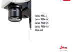
An Overview of the Leica MZ10 F
1 Eyepieces with dioptric correction
2 Binocular tube
3 Fluorescence housing
4 Filter Changer
5 Magnification (zoom)
6 Leica MZ10 F
7Objective
8 UV protection screen
9 Transmitted light base
10 Focus column
11 UV Shutter
12 System Illumination EL6000
1
10
2
3
4
5
11
6
7
8
9
12
Leica MZ10 F
User Manual
44
The Correct Interpupillary Distance
The interpupillary distance is correctly set if you
see a single circular image field when looking
at a specimen.
If you are still a novice microscope user, you
may need a short time to become accustomed
to this. Not to worry—after a little while, it will
become automatic.
Adjusting the interpupillary distance
1. Look into the eyepieces.
2. Hold the eyepieces with both hands. Push
the eyepieces together or separate them
until you see a circular image.
Reference value
The distance between eye and eyepiece measures approx. 22 mm for
10/23B wide-field eyepieces for persons
wearing glasses.
Leica MZ10 F
3. Slowly approach the eyepieces with your
eyes until you can see the complete image
field without corner cutting.
✗
User Manual
✓
45
Using the Eyepieces
The eyepieces form the connection between
the tube and the eye of the observer. Simply
push them into the tube and they are ready to
use.
If you do not wear glasses:
1. Hold the eyepiece firmly and rotate the
eyecups forwards counterclockwise.
If you wear glasses:
1. Hold the eyepiece firmly and rotate the
eyecups clockwise towards the rear, as
otherwise the viewing distance is too great.
2. If an eyepiece is equipped with the integEach eyepiece offers a certain magnification
factor that has a determinative effect on the
total magnification. Furthermore, all Leica
eyepieces can be equipped with practical graticules that enable measuring and quantifying of
specimens.
Dioptric Correction
A built-in dioptric correction is available for
eyeglass wearers. For more information, refer to
Page 56.
rated dioptric correction, turn the value to
the "0" mark.
2. If an eyepiece is equipped with the integrated dioptric correction, turn the value to
the "0" mark.
By the way, one benefit of viewing with
eyeglasses is a drastically lower risk of bacterial
transmission. The soft material of the eyecup
also ensures that your glasses will not be scratched, even if they contact the eyepiece.
Leica MZ10 F
User Manual
46
Focusing
Focusing raises or lowers the stereomicroscope
using the focusing drive. The specimen detail is
brought into sharp focus as soon as it is in the
focal point of the objective.
▶▶ The focusing drive can be operated either
left- or right-handed.
Leica MZ10 F
Focusing
▶▶ The inner, coarse adjustment is used for
covering great distances.
▶▶ The outer, fine adjustment is used for fine
focusing.
User Manual
Coarse/fine adjustment
The sharpness is adjusted using the coarse/fine
adjustment. The resolution of the coarse/fine
adjustment is 1 µm.
• up to 15 kg.
The coarse/fine adjustment carries a load of
47
Adjusting the Resistance of the Focus Drive
Adjusting the resistance
Is the focusing drive too loose or too tight? Does
the equipment tend to slide downwards? The
resistance can be adjusted individually depending on the equipment weight and personal
preferences as follows:
1. Grip the outer drive knobs with both hands
and turn them towards each other until the
desired resistance is reached during focusing.
Leica MZ10 F
User Manual
48
Changing Magnification (Zoom)
ted zoom. The name indicates the zoom
All M series microscopes have an integra-
range covered. The MZ10 F covers a zoom range
of 10:1.
The rotary knob for the zoom can be
used either left or right-handed.
Leica MZ10 F
Zooming
1. Look into the eyepieces.
2. Focus on the specimen.
3. Rotate the magnification changer until the
desired magnification is configured.
User Manual
49
Double Iris Aperture
The built-in double-iris diaphragm regulates
the depth of field. Note that:
▶▶ The greater the depth of field, the darker
the image becomes.
▶▶ In the same way, the exposure time becomes longer for photographs.
▶▶ The resolution decreases.
Leica MZ10 F
Iris closed
Iris open
User Manual
50
Ratchet Steps and Magnification Levels
The zoom button can optionally be operated
either with or without ratchet steps. Continuous zoom is possible when the ratchet steps
are disabled, which many users find convenient.
On the other hand, when the ratchet steps are
enabled, photographs, measurement results
etc. can be reproduced more accurately.
Leica MZ10 F
Enabling and disabling ratchet steps
1. Push the front button backwards to disable
the ratchet steps.
2. Push the rear button forwards to enable the
ratchet steps.
User Manual
Magnifications and
fields of view
The formula on Page 106 provides additional
information about the magnifications and field
of view diameters, with consideration given to
the position of the magnification changer and
the eyepiece and objective combination used.
51
Parfocality: More Comfort and Convenience for Your Work
All Leica stereomicroscopes are parfocally
matched, meaning that you can view a focused
specimen from the lowest to the highest
magnification without having to refocus. The
focus needs to be readjusted only if you want
to view a specimen detail that is located higher
or lower.
Requirements for parfocal work
▶▶ If you are using an eyepiece with dioptric
correction, the procedure differs from this
description. For more information, refer to
Page 57.
Leica MZ10 F
Parfocality
1. Enlarge the view to the maximum level.
2. Focus on the specimen.
You are done! Even if you select a smaller
working distance, the specimen remains pinsharp.
The parfocality is maintained until you focus on
another level of the specimen.
User Manual
52
Eyepieces
Leica MZ10 F
User Manual
53
Magnification Factors of the Eyepieces
An eyepiece not only makes it possible to look passively into the microscope, but also has a critical effect on the maximum magnification. The
magnification factor is between 10x and 40x.
The following eyepieces are available for the M series:
Magnification
Dioptric Correction
Order number
10×
± 5 diopter settings
10 450 023
16×
± 5 diopter settings
10 450 024
25×
± 5 diopter settings
10 450 025
40×
± 5 diopter settings
10 450 026
Leica MZ10 F
User Manual
54
Health Notes
Potential sources of infection
Direct contact with eyepieces is a potential transmission method for bacterial and
viral infections of the eye. The risk can be kept
to a minimum by using individual eyepieces or
detachable eyecups. Eyecups can be ordered
separately. Please contact your Leica partner.
• Separate eyecups are an effective way of preventing infections.
Leica MZ10 F
User Manual
55
Dioptric Correction
All Leica eyepieces are also available with builtin dioptric correction, allowing the microscope
to be used without glasses even by those with
vision problems. The correction comprises ±5
diopter settings.
Using the Dioptric Correction
1. Set the dioptric correction of both eyepieces to the mid position ("0" diopter
settings).
2. While wearing your glasses, look through
the eyepieces and focus on the specimen.
the advantage of parfocality is lost - thus
Note that when using dioptric correction,
you have to manually refocus each time you
change the zoom level. To also use parfocality
with dioptric correction, refer to the instructions on Page 57.
3. Rotate both eyepieces to the maximum
value of "+5".
4. Hold one eye closed and rotate the other
eyepiece in the "-" direction until the specimen appears sharp.
5. Then, open the other eye and correct the
diopter settings until the image is uniformly
sharp.
Leica MZ10 F
User Manual
56
Dioptric Correction and Parfocality
Leica stereomicroscopes are parfocally
matched. The prerequisite for this is the correct
setting of the diopters and the parfocality. The
following adjustments have to be carried out
only once by each user.
Adjusting
1. Set the dioptric correction for both eyepieces to "0".
Preparations
▶▶ Move the lever of the video/phototube to
the "observation" position and open the
diaphragm.
3. Select the highest magnification and readjust the sharpness.
▶▶ If you are using the microscope carrier AX,
set it to stereoscopic observation.
Leica MZ10 F
2. Select the lowest magnification and focus
on a flat specimen.
4. Select the lowest magnification again, but
do not look into the eyepieces.
7. Look into the eyepieces.
8. Slowly rotate each eyepiece individually
in the "–" direction until each eye sees the
object sharply imaged.
9. Select the highest magnification and refocus if necessary.
Now, if you adjust the magnification from the
lowest to the highest level, the specimen is
always brought into sharp focus. If not, repeat
the process.
6. Rotate the eyepieces counterclockwise in
the "+" direction as far as they will go (+5
diopter settings).
User Manual
57
Graticules
Use
Leica graticules make length measurements
and counting easier, particularly for workstations that are not equipped with a digital
camera and LAS software.
2. Clamp the graticule on the insert, applying
moderate pressure. Ensure that the graticule fits tightly.
4. You can now align the graticule by rotating
the eyepiece in the tube and then tightening it using the clamping screw.
The Leica graticules for length measurements
and numbering are fitted in mounts and are
inserted into the eyepieces.
1. Screw the insert off of the eyepiece.
3. Screw the insert and graticule firmly into
place and replace the eyepiece in the tube.
Use with the Leica AX carrier
Due to the convergence angle in the
stereoscopic image, measurements can
provide only approximate values.
Leica MZ10 F
User Manual
58
Photography & Video
Leica MZ10 F
User Manual
59
Photography & Video
For most microscope users, digital documentation has become an invaluable part of their
work. Research results can be presented in an
attractive manner; measurements on the digital image provide clarity and, in conjunction
with the motorized IsoPro™ cross-stage, even
images of large specimens can be captured
step by step and automatically joined to create
a new complete image.
Leica DFC cameras
However, if you require absolute control over
the camera and need the capability for measurement, evaluation and more in addition to
photography, the digital Leica DFC cameras are
exactly right for you. Together with the Leica
Application Suite, they provide virtually limitless freedom of use. For additional information about Leica cameras, refer to the camera's
documentation.
Leica Application Suite
The "Leica Application Suite", or "LAS" for short,
is, as it were, the digital extension of the Leica
M series microscopes. In addition to capturing
images, it lets you control the microscope, illuminator, stages, cameras and more. For additional information, refer to the LAS online help.
Adapters
If camera control using the Leica Application
Suite is not required, conventional mirror reflex
and rangefinder cameras from third-party
manufacturers can be used. For this purpose,
Leica Microsystems offers a variety of adapters
that can be used together with the 50% and
100% trinocular tubes.
Leica MZ10 F
User Manual
60
Photo Tubes and C-mounts
Application
All Leica DFC cameras are equipped with a
standardized C-mount interface. In turn, the
C-mount adapter for the respective trinocular
tube is connected to this interface. This adapter
creates a solid mechanical connection between
the microscope and camera and ensures optimum rendering of the microscopic image on
the image sensor of the camera.
Usually, the ideal is for the digital camera to
capture as much of the field of vision as possible, while excluding as much of the black edge
of the field of vision as possible. To do so, the
magnification factor of the C-mount adapter
must match the image format of the sensor as
closely as possible (see table).
Leica MZ10 F
If there is unwanted shading at the corners even
with a compatible C-mount adapter installed, it
can be corrected using the "Shading function"
of the camera software.
Alternatively, you can also use a C-mount adapter with higher magnification. This primarily
avoids the critical border area of the field of
vision and concentrates on the center of the
field of vision.
Camera
DFC290
optimal
(large
image field)
suitable
(smaller
image field)
0.5×
0.63×
DFC420
0.5×
0.63×
DFC490
0.63×
0.8×
DFC500
0.63×
0.8×
User Manual
Cameras from third-party suppliers
In addition to Leica DFC cameras with the standardized C-mount interfaces, you can connect
third-party cameras to the microscope using
a T2 bayonet adapter. To do so, instead of the
C-mount adapter, simply use the corresponding SLR adapter with T2 connection. However,
these third-party cameras are not integrated
into the Leica Application Suite and have to
be operated using the corresponding software
from the camera manufacturer.
The Leica digital cameras are detailed in a separate user manual along with instructions for
their assembly and use.
61
Trinocular Video/Phototube 50%
Use
With its third beam path, the trinocular video/
phototube 50% enables you to simultaneously
view and photograph a specimen. The available
light is divided as follows:
▶▶ 50% is available for the two eyepieces.
▶▶ 50% of the light is diverted to the video/
photo beam path.
Assembly
Fasten the "trinocular tube 50%" to the optics
carrier instead of the binocular observation
tube.
Leica MZ10 F
User Manual
62
Trinocular Video/Phototube 100%
Use
With its third beam path, the trinocular video/
phototube 100% enables you to either view or
photograph a specimen. This means that 100%
of the light is available to one or the other beam
path. The other beam path remains opaque or
black.
Assembly
Fasten the "trinocular tube 100%" to the optics
carrier instead of the binocular observation
tube.
Leica MZ10 F
Toggle
▶▶ Turn the controller on the right side of the
tube into the horizontal position in order to
guide all available light into the eyepieces.
You can now observe the specimen.
▶▶ Turn the controller on the right side of the
tube into the vertical position in order to
guide all available light into the camera.
You can now photograph the specimen.
User Manual
63
Objectives and
Optical Accessories
Leica MZ10 F
User Manual
64
The Different Types of Objectives
To meet the various requirements regarding
imaging properties, there is a choice of highquality interchangeable planachromatic and
planapochromatic objectives and also lowerpriced interchangeable achromatic objectives.
▶▶ Achromatic objectives are particularly
suited for specimens with high-contrast
structures.
▶▶ Flat-field (planachromatic) objectives are
particularly well suited for studying flat
objects such as wafers and thin sections.
▶▶ With planapochromatic objectives, the
finest structures are visible with high
contrast. The sophisticated apochromatic
correction allows these objectives to attain
the highest color brilliance and fidelity. We
recommend the planapochromatics of the
M series (article numbers 10 450 027 to 10
450 030).
Leica MZ10 F
User Manual
65
Bases
Leica MZ10 F
User Manual
66
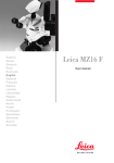
Leica TL ST Transmitted Light Base: Controls
1
2
1
3
4
Extension plate of the Transmitted Light Base
TL ST
1 Adapter plate for easy assembly of focusing drives
2 Removable glass plate
3 Controller for light intensity
4 Adjustment for path-folding mirror
Leica MZ10 F
User Manual
2
3
Rear side of the transmitted light base TL ST
1 Screws for changing the halogen lamp
2 Power connection socket
3 Power switch
67
Leica TL ST Transmitted Light Base: Operation
Light intensity control
The left control adjusts the intensity of the
12 V/20 W halogen illumination.
1. Switch on the illumination of the base at
the power switch.
Transmitted light control
The transmitted light base TL ST has a slider that
automatically moves the path-folding mirror in
the base when moved. The mirror is kept in the
correct position at all times and permits smooth
changeover between bright field and opaque
transmitted light.
Bright field
Bright field is suitable for examining translucent objects featuring contrasting structures.
The object is directly illuminated from below
and is seen in its natural colors against a bright
background.
▶▶ Move the slider backwards until the desired
effect is achieved.
2. Focus on the specimen.
3. Set the illumination to the desired intensity
using the left control.
Inclined transmitted light
Transmitted light that traverses the object obliquely will provide additional resolution and
information when observing semitransparent,
opaque objects.
▶▶ Slowly pull the slider towards yourself until
the desired effect is achieved.
Leica MZ10 F
User Manual
68
Leica TL ST Transmitted Light Base: Changing lamps
Changing the halogen lamp
Before you change the lamp, it is absolutely
necessary to unplug the power plug from
the base to prevent the risk of electric shock!
• Changing lamps
1. Unscrew the two screws on the heat sink
and pull the heat sink out, along with the
lamp.
Precautionary measures
When inserting the lamp, ensure that the
cables are inside the two metal clamps. This
prevents the cables from getting caught during
insertion.
• during operation. Therefore, to avoid
The halogen lamp becomes very hot
being burned, let the base cool off for approx.
10 minutes after switching it off!
• bare fingers—this drastically reduces the
Do not touch new halogen lamps with your
service life of the lamp!
2. Carefully pull out the lamp and mount by
pulling them upwards.
3. Disconnect the lamp from the mount.
4. Insert the new lamp into the mount and
reinsert the lamp holder.
Leica MZ10 F
User Manual
69
Leica TL BFDF Transmitted Light Base: Controls
1
2
3
Extension plate of the Transmitted Light Base TL
BFDF
1 Adapter plate for easy assembly of focusing drives
2 Standard stage 10 447 269
3 Button to toggle between bright field and
dark field
Connector for cold light sources
(fiber-optic light guide active f = 10 mm, end
tube f = 13 mm)
Button to toggle between bright field and dark
field
Leica MZ10 F
User Manual
70
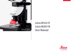
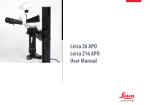
Leica TL BFDF Transmitted Light Base: Operation
Light intensity control
Please observe the user manual—in particular, all safety regulations—from the
manufacturers of the light guide and cold light
source.
• ▶▶ Switch on the cold light source according to
the manufacturer's user manual and adjust
the brightness.
Bright field
Bright field is suitable for examining translucent objects featuring contrasting structures.
The object is directly illuminated from below
and is seen in its natural colors against a bright
background.
▶▶ Turn the control as far as it will go towards
"BF" ("bright field").
Dark field
In dark-field illumination, a ring illuminator is
used in such a way that the direct light
does not reach the objective without a specimen. Only the structure of semitransparent,
opaque objects disperses the light, making the
object visible against a dark background.
▶▶ Turn the control as far as it will go towards
"DF" ("dark field").
Transmitted light control
The Leica TL BFDF transmitted light base has
a control that switches the light from "bright
field" to "dark field".
Fingertip with bright field illumination
Leica MZ10 F
User Manual
Identical subject with dark field illumination
71
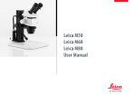
Leica TL RC™ / TL RCI™: Controls
1
2
1
2
3
4
5
6
7
3 45
Vertical column - transmitted light base adapter
plate
1 Heat sink of the integrated halogen illumination (only TL RCI™)
2 Extension plate for focusing drives
3 Standard stage 10 447 269
4 Filter holder
5 Control of top and bottom flaps of the
Rottermann Contrast™
6 Button for mirror and horizontal movement of the mirror
7 Transmitted light base
Leica MZ10 F
User Manual
1
2
3
4
5
6
6
Power switch
Power connection socket
USB socket, type B
USB socket, type A
2× CAN bus
Screws for changing the halogen lamp
72
Leica TL RCI™: The Path-folding Mirror
1
Inverted world?
Depending on the properties of the specimen
(refractive index of the environment) and the
perception of the viewer, it is possible that the
switches described below for positive and inverted relief contrast are to be operated in reverse.
This means that the lower switch, rather than
the upper switch, controls the inverted relief
contrast and vice-versa.
Leica MZ10 F
Tilted mirror
The built-in mirror features one flat and one
concave side and can be rotated and moved.
The concave side has been specially designed
for the optical requirements of objectives with
a high numerical aperture. The black rotary
knob on the left side of the transmitted light
base can be used to rotate the built-in pathfolding mirror and move it forwards/back.
Functions of the rotary knob
The rotary knob (1) fulfills the following tasks:
The concave cutout on the handle indicates the
concave side of the mirror, allowing intuitive
operation at any time without eye contact.
▶▶ Moving the path-folding mirror (forwards/
back).
▶▶ Turning the path-folding mirror from the
flat to the concave side.
▶▶ Slightly tilting to guide the light beam
through the specimen plane at a steeper or
flatter angle.
The angle of light incidence in the specimen
plane changes depending on the tilt and
position of the mirror. As a result, switching
between transmitted light bright field, oblique
illumination and dark field-like illumination is
possible.
User Manual
73
Leica TL RCI™: Color Intensity and Temperature
The transmitted light base TL RCI™ has two
electronic potentiometers that control the color
intensity (1) and color temperature (2).
The controller for the color temperature simultaneously serves as an electronic shutter:
▶▶ To interrupt your work, click the potentiometer (2).
1
2
1 Potentiometer for controlling the CCIC™
(Constant Color Intensity Control) illumination intensity
2 Potentiometer for controlling the color
temperature
Leica MZ10 F
▶▶ Click again to switch on the illumination.
The electronics returns the color temperature to the previously configured setting.
Using a USB mouse (only TL RCI™)
The Leica USB mouse controls the CCIC™ and
dimming function of the TL RCI™ base. Connect
the mouse to the corresponding USB port of
the base.
▶▶ The scroll wheel of the mouse is occupied
by default with the CCIC™ control system
and is used to control the illumination
intensity.
▶▶ To switch the illumination on or off, briefly
click the scroll wheel.
▶▶ To enter or exit dimming mode, click and
hold down the scroll wheel for longer than
2 seconds.
User Manual
74
Leica TL RC™ / TL RCI™: Operation
Setting the relief contrast
The two switches on the left side of the transmitted light base TL RC™/TL RCI™ activate two
built-in flaps. The outer switch (1) controls the
inverted relief contrast, and the inner switch (2)
adjusts the positive relief contrast.
1
2
Depending on the flap position, a part of
the opening of the built-in Fresnel lenses are
covered, which results in the different contrast
effects. Phase structures typically act as spatial,
relief-type images—in the positive relief contrast like hills, in the inverted relief contrast like
valleys.
Increased contrast without relief is attained
if both diaphragms are set to 45°. A gap-like
illuminated area is created. By tilting the pathfolding mirror slightly, you can move the gap
over the entire field of view and quickly toggle
between positive and negative relief images.
The dynamic effect makes it easy to distinguish
phase structures from amplitude structures.
3
1 Switch for adjusting the inverted relief
contrast
2 Switch for adjusting the positive relief
contrast
3 Path-folding mirror
Leica MZ10 F
User Manual
75
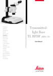
Leica TL RCI™: Methods in Transmitted Light
Vertical bright-field illumination
Suitable for stained amplitude specimens with
sufficient contrast.
The light beams are deflected vertically through
the
specimen. This results in an accurate bright field
with maximum brightness.
Leica MZ10 F
Inclined transmitted light
Suitable for semitransparent, opaque specimens such as foraminifera and fish eggs. Move
the path-folding mirror until the desired data
are visible.
User Manual
Single-sided dark field
Suitable for fixed specimens and fine structures.
The flatter the angle at which the light beams
are deflected into the specimen plane, the
darker the substrate appears. A dark field-like
transmitted light is created. Outlines, fine edges
and structures are bright, in contrast with the
dark background, through diffraction of the
light beams on the dark background.
76
Leica TL RCI™: Relief Images
Starting position
1. Push the path-folding mirror all the way
back towards the column.
2. Turn the path-folding mirror into the notch
position at an angle of 45°.
Leica MZ10 F
Positive relief contrast
Suitable for semitransparent and transparent
specimens. The phase structures look like hills.
The effect can be strengthened or weakened by
gently tilting the path-folding mirror.
User Manual
Negative relief contrast
Suitable for semitransparent and transparent
specimens. These settings result in a negative
relief contrast. Phase structures look like valleys.
The effect can be strengthened or weakened by
gently tilting the path-folding mirror.
77
Leica TL RCI™: Relief Images (cont'd.)
Dynamic relief contrast
Suitable for semitransparent and transparent
specimens.
By tilting the path-folding mirror slightly, you
can move the gaps over the entire field of view
and quickly toggle between positive and negative relief images. The dynamic effect makes
it easy to distinguish phase structures from
amplitude structures.
Leica MZ10 F
Constraints
The relief methods provide good results from
mid-zoom to high magnifications and with 1×,
1.6× and 2× objectives. In the lower zoom half
and with weaker specimens, the object field
may not be uniformly illuminated.
We recommend using the transmitted light
base with 1× or higher objectives, and not
objectives with a long focal length.
User Manual
78
Using Filters
Filters for Leica TL RC™ and TL RCI™
The transmitted light bases TL RC™ and TL RCI™
can be equipped with up to three filters—
available as accessories—simultaneously. By
customer request, the filters are also available
as one-off items.
2. Take the empty filter from an available filter
slot in the filter holder.
Daylight filter for Leica TL ST
A daylight filter is also available for the Leica TL
ST transmitted light base.
3. Insert the desired filter.
1. Switch off the light source or click (Leica TL
RCI™) the button for the shutter.
4. Switch the light source back on.
Leica MZ10 F
User Manual
79
Leica IsoPro™ (Non-motorized): Controls
Operating the Leica IsoPro™ Cross-stage
1. To move the stage in the X direction, rotate
the outer knob.
2. To move the stage in the Y direction, rotate
the inner control ring.
1
Leica MZ10 F
2
User Manual
80
Leica IsoPro™ (Motorized): Controls
IsoPro
X/Y Stage DCI module
1
Leica PSC Controller
1
2
2
3
1
1 Leica IsoPro™ Motorized Cross-stage
2 Housing with motorization
Leica MZ10 F
1
2
3
4
2
3
4
Sub-D interface for Leica SmartMove™
3 CTL2 interfaces
USB interface (type B)
Socket for grounded power cable
User Manual
1 Quick control/memory function
2 Fine control in X direction
3 Fine control in Y direction
81
System Illumination Leica EL6000
Leica MZ10 F
User Manual
82
Leica EL6000 – About the Instrument
The Leica EL6000 compact light source is
Special features:
The Leica EL6000 compact light source has an
automatic beam cover. This ensures that the
light beam output of the instrument when the
light guide is detached. This prevents the user
from being harmed by the intense light beam
generated by the instrument.
Heat-absorbing filter
When the cover is open, the holder for the heat
filter can be accessed. Here, (hardened) heatabsorbing filters for protecting the light guide
and various conversion filters with a diameter
of 32 mm for adapting the spectrum to the
application can be inserted.
short-arc lamps of type HXP-R120W/45C VIS
from OSRAM in conjunction with a suitable
light guide for the instrument. Any other use of
the instrument shall be considered noncompliant use.
The Leica EL6000 compact light source has a
built-in shutter. It can be operated at the instrument itself by means of a pushbutton or via a
remote control input. The shutter is open when
the "open" LED is illuminated.
The Leica EL6000 comes factory-equipped with
a heat-absorbing filter.
The Leica EL6000 compact light source is intended for biological routine and research work,
including the examination of specimens from
the human body for the purpose of gaining
information.
• intended exclusively for operating mercury
The brightness can be varied in 5 increments
(0% – 100%). For this purpose, a mechanical
dimming unit that can be operated using a
rotary switch on the front of the unit is installed
in the device.
Leica MZ10 F
User Manual
83
Leica EL6000 – About the Instrument (continued)
Compatible light guides
The Leica EL6000 compact light source is
compatible with liquid light guides that are
compatible with a "Storz long" light inlet and
whose transmission curve fits the lamp used.
Where applicable, refer to the lamp's data sheet
for its spectral light distribution.
Identification of the instrument
The nameplate of the instrument is on its
bottom. It includes the necessary information
for identifying the instrument.
The Leica EL6000 compact light source complies
with Council Directive 98/79/EC concerning in
vitro diagnostics. It also conforms to the Council Directives 73/23/EEC concerning electrical
apparatus and 89/336/EEC concerning electromagnetic compatibility for use in an industrial
environment.
When connecting the light guide to the light
source or the microscope adapter, make sure
not to kink or damage the light guide.
Your Leica consultant will be glad to provide
additional information about suitable light
guides.
Leica MZ10 F
User Manual
84
Leica EL6000 – Operation
Controls
Running-time meter
The running-time meter measures the burning
time of the lamp, not the switch-on time of
the Leica EL6000 compact light source. The
running-time meter displays its current status
in this format: hours – minutes.
1. Press the reset button to set the runningtime meter of the lamp to "0".
5
The running-time meter should be reset after
every lamp replacement so that it always
displays the current, accurate lamp life.
4
1
2
3
4
5
3
2
1
Power switch/power indicator
Reset button for running-time meter
Running-time meter
Shutter control
Intensity switch
Leica MZ10 F
Shutter control
▶▶ In the "open" position, the shutter of the
Leica EL6000 is open—regardless of the
signal from the remote control.
▶▶ If the shutter control is in the "remote" position, the shutter is controlled by the remote
control.
Intensity switch
The intensity switch provides optical dimming
of the light in five fixed increments.
Discontinue using the built-in lamp when it
reaches the end of the life specified by the
manufacturer.
User Manual
85
Leica EL6000 – Troubleshooting
Fault description
Power indicator is not illuminated after being
switched on, instrument shows no function
Power switch is illuminated after being switched
on, instrument shows no function
Target system receives too little light or none at all
Possible faults
Remedy
No power supply voltage present; connecting
cable not plugged in correctly/defective
Check power supply voltage and connecting
cable
Fuses in instrument defective
Replace fuses, use permitted replacement
type only
Housing cover loose
or removed
Attach housing cover securely
Lamp worn out
Replace lamp
Shutter closed or intensity switch at left limit
stop
Open shutter or rotate intensity switch
towards the right
Light guide not inserted into light guide
output properly
Check light guide
Light guide damaged/defective
Repair or replace
If these actions do not fix the problem, send the Leica EL6000 compact
light source to Leica service with an exact description of the malfunction.
Leica MZ10 F
User Manual
86
Leica EL6000 – Cleaning and Maintenance
• off the Leica EL6000 compact light source.
Before carrying out cleaning tasks, switch
Use only a dry, lint-free cloth for cleaning. When
cleaning, ensure that no dust or other foreign
bodies enter the device through the ventilation
slots.
In case of damage (even external damage),
immediately stop using the Leica EL6000
compact light source and send it to service.
If it will not be used for a long time, protect the
Leica EL6000 compact light source from dust
using a suitable cover (such as the plastic bag
from the original packaging).
Leica MZ10 F
Spare parts and accessories
The only parts of the Leica EL6000 compact
light source that may be replaced by the user
are the instrument fuses and the lamp.
Permitted replacement fuses
Fuse: 5×20, 2.5 A, slow-blowing, breaking capacity H
Wickmann Series 181
www.wickmann.com
Schurter Series SPT 5×20 www.schurter.ch
▶▶ The replacement of the lamp is described
on Page 88.
Replacing the instrument fuse
1. Disconnect the Leica EL6000 from the
power supply.
2. Open the drawer with the instrument fuses
located close to the power supply input.
Repairs
Opening or working on the Leica EL6000
compact light source in any manner other than
described above (changing lamps, changing
fuses) may be carried out by the supplier of the
instrument or the supplier's authorized representatives.
3. Replace the instrument fuse.
User Manual
87
Leica EL6000 – Replacing the Lamp
The procedure for replacing the lamp does not
differ from the installation procedure outlined
on Page 38, except for the fact that the existing lamp has to be removed first.
3. Remove the housing cover.
Replacing the lamp
The lamp used in the instrument becomes very hot during operation and has
high internal pressure when hot. Before changing the lamp, it is mandatory to allow the instrument to cool off for at least 20 minutes.
This makes it easier to replace the lamp.
1. Pull the power plug out of the socket, so
that the EL6000 is disconnected from the
power system.
4. Carefully lay the Leica EL6000 on its side so
that the opening faces you.
5. Pull the pressure bolt back towards the
front plate using the lever.
6. Pull out the lamp and disconnect the plug
from the coupling in the instrument.
7. Install the new lamp as outlined on Page
38, beginning with item 6.
2. Unscrew both screws of the cover using a 3
mm Allen key.
Leica MZ10 F
User Manual
88
Fluorescence
Leica MZ10 F
User Manual
89
Filter Changer
The patented FLUOIII® filter system consists of
a filter changer for barrier and excitation filters,
a UV shutter that can be activated/deactivated,
and a filter insert for a filter holder with your
choice of filter.
The filter changer can hold a total of 4 filter sets.
The filter sets for fluorescence are labeled.
• with fluorescence filters, always insert the
If you are using fewer than four filter holders
included simple filter holders with closed illumination beam path into the available positions. Otherwise, there is a risk of danger to the
eyes from direct UV radiation from the third
beam path.
The scope of delivery of the Leica MZ10 F includes four filter holders for empty filter positions
and transmitted or incident light observation
without fluorescence. These filter holders have
two empty openings for the observation beam
paths. The third opening, to the illumination
beam path, is closed.
system from dust.
The simple filter holders also protect the
Filter sets for fluorescence
The filter sets for fluorescence contain, on one
filter holder, two barrier filters to the visual
beam paths and one excitation filter to the illumination beam path. The filter sets are labeled.
A selection of the available filters
including simple filter holder (bottom right)
Leica MZ10 F
User Manual
90
About Fluorescence Microscopy
Functional principle
Fluorescent substances light up when irradiated with short-wave excitation light, and fluorescence microscopy takes advantage of this
property. Specimens without self-fluorescence
are stained with a fluorescent substance. One
such dye is green fluorescent protein (GFP),
which is used in molecular biology.
Leica MZ10 F
The Leica M Series
The Leica M series fluorescence stereomicroscopes allow entire fluorescent specimens to
be studied, unprepared and in three dimensions. The fully apochromatic optics system and
the large zoom range make the Leica M series
stereomicroscopes your first choice. The patented TripleBeam® third beam path for fluorescence illumination and the patented FLUOIII®
filter system generate highest-quality fluorescence images. The very bright high-pressure
mercury burner and specially selected filter sets
enable you to distinguish the finest structures
and enhance the quantity of information for
incident light fluorescence.
User Manual
The filter system
The FLUOIII® filter system consists of a rapid
filter changer for barrier and excitation filters
and a filter insert for a filter holder with your
choice of filter. A total of four filter sets (which
are labeled) can be used in the rapid filter changer. An empty filter cartridge is also available
for individual filter combinations. Each filter set
includes two barrier filters to the visual beam
paths and an excitation filter to the illumination
beam path.
91
Simple filter holders
Simple filter holders
Three simple filter holders are included with
the Leica MZ10 F. These filter holders have two
empty openings for the observation beam
paths. The third opening, to the illumination
beam path, is closed.
▶▶ Use this filter holder if you want to work
briefly (no more than 15 seconds) without
fluorescence illumination.
it must not block the mercury light for
So that the filter holder is not heated,
Safety Notes
▶▶ If you want to block the mercury light for
longer than that, activate the UV shutter.
▶▶ Use the filter if you want to change to transmitted light or incident light observation
without fluorescence.
• with fluorescence filters, always insert the
If you are using fewer than four filter holders
included simple filter holders with closed illumination beam path into the available positions. Otherwise, there is a risk of danger to the
eyes from direct UV radiation from the third
beam path.
▶▶ Always place a simple filter holder into the
empty filter changer positions in order to
protect yourself from UV radiation and
protect the system from dust.
longer than 15 seconds.
Leica MZ10 F
User Manual
92
Equipping the Filter Changer
• touching the filters in order to avoid fingerWhen inserting the filter sets, avoid
prints. Clean dirty filters immediately using a
soft, lint-free cloth and pure alcohol.
Removing the simple filter holder
The Leica MZ10 F is equipped at the factory
with simple filter holders as "dummies". These
must be removed before inserting a filter.
1. Grasp the recess of the dummy in the filter
changer and pull it out.
Inserting the filter
1. Place the filter into the filter changer.
Ensure that the contour of the filter holder
matches the contour of the microscope.
2. Rotate the filter changer by hand until it
latches into place.
If the filter holder has not been inserted
correctly, the filter changer does not rotate.
3. Insert a total of four filters.
Slot for filter slide
There is a slot in the filter changer system for
an individually selectable filter, for example a
neutral density filter.
Leica MZ10 F
User Manual
93
Observation without Fluorescence
yourself with the controls of your Leica
We recommend that you first familiarize
fluorescence microscope in transmitted light
without the presence of fluorescence illumination.
• mercury burner, you must adjust the arc
After switching on the high-pressure
lamp immediately (see User Manual M2-216-1).
yourself with the basic functions of your
We recommend that you first familiarize
Leica stereomicroscope as they are described in
the previous section of this User Manual. These
include the binocular tube, the eyepieces, the
zoom magnification changer, the focusing
drive, and others.
Observation without Fluorescence
The FLUOIII® filter system includes a UV shutter
that can be used to close the illumination beam
path. This feature protects the mercury lamp,
which should not be switched on and off too
frequently. If, for instance, you need to interrupt your work, you do not have to switch off
the high-pressure mercury burner to preserve
sensitive specimens from being burned out or
bleached out.
burner on and off frequently decreases
Close the UV shutter when you do not want to
view the specimen with fluorescence illumination, but only with transmitted light.
Switching the high-pressure mercury
its life and causes delays, as the lamp can only
be switched back on after it has cooled. Instead,
you can close the UV shutter and reopen it
when you return to your workplace.
Shutter open
The following describes the specific functions
of the fluorescence system only.
Shutter closed
Leica MZ10 F
User Manual
94
Commissioning the Fluorescence System
After switching on the high-pressure mercury
burner, you must adjust the arc lamp immediately (see User Manual M2-216-1). Do not switch
on the supply unit until you feel confident using
the Leica stereomicroscope.
Using the protection screen
For observation with fluorescence light,
always position the protection screen
correctly to protect the observer.
• mercury lamps and the lamp housing!
Using the Leica EL6000
Be sure to observe the instructions for the
Leica EL6000 starting on Page 82.
Follow all safety instructions when handling
1. Switch on the supply unit (see User Manual
M2-216-1).
• • 2. Wait 2–3 minutes.
3. Adjust the arc lamp in accordance with User
Manual M2-216-1.
Leica MZ10 F
User Manual
95
Dimensional Drawings
Leica MZ10 F
User Manual
96
MZ10 F - dimensioned drawings in mm
Leica MZ10 F
User Manual
97
Specifications
Leica MZ10 F
User Manual
98
Leica MZ10 F – Specifications
Specifications
Zoom ratio
Optics carrier magnification
Design engineering
Standard magnification
Standard objective
Illumination
Filter Changer
Illumination control
Diameter of the field of view
Maximum resolution
Numerical Aperture
Click stops for
Leica MZ10 F
10:1
0.8×–8×
CMO (Common Main Objective) optics
8×–80× (10× eyepiece & 1.0× objective)
Planapochromatic 1.0× (NA = 0.125)
TripleBeam™ – Third (separate) illumination beam path with automatic
adjustment (via zoom) to the field of view
FLUOIII™ – 4 positions, manual
Manual excitation shutter
131–1.31 mm (max./min.)
1.33μ (750 lp/mm)
0.25 (max.)
1× / 1.6× / 2× / 2.5× / 3.2× / 4× / 5× / 6.3×
User Manual
99
Leica EL6000 – Specifications
Dimensions (W×H×D)
Width×height×depth
Environmental conditions
Permitted ambient temperature
Permitted relative humidity
130 mm × 210 mm × 290 mm
-20 to 85 °C
10% to 90%,
non-condensing
Operation
Permitted ambient temperature
0 to 40 °C
Permitted relative humidity
10% to 90%, non-condensing
Operational data
Application area
Enclosed rooms
Altitude for use
max. 2000 m above sea level
Protective class
I
Type of protection
IP20 (EN 60529)
EMC
Emitted interference
EN 61326 (Class B)
Immunity to interference
EN 61326 Appendix A
Voltage fluctuations, flicker
EN 61000-3-3
Harmonic currents
EN 61000-3-2
The instrument fulfills the requirements of EC Directive 89/336/EEC and
the EMC law of September 18, 1998
Leica MZ10 F
Electrical safety
in accordance with EN 61010-1:2001
Pollution degree
Overvoltage category
Power input
Design
Power supply voltage
Power frequency
Fuse protection
Power consumption
Lamp
Type
2
II
Switched socket IEC320 C13
(EN 60320 C13)
100 to 240 VAC (±10%)
50 to 60 Hz
2x T2.5 A; Breaking capacity
H (manufacturer: Wickmann;
Series 181)
Max. 210 VA
Mercury short-arc reflector
lamp
Designation
OSRAM HXP-R120W/45C VIS
Power consumption
120 W
Service life (manufacturer information) Average value 2000 h
User Manual
100
Leica EL6000 – Specifications (cont'd.)
Light output
Design
Special feature
Fan
Switch-on delay
Interface
Type
Design
Remote signal level
– Shutter closed
– Shutter open
– Input current
Footswitch
– Shutter closed
– Current
Shutter frequency
Leica MZ10 F
Type: Storz, long
Self-locking if no light guide is
plugged in
Approx. 60 s after lighting the
lamp
Remote control input for internal shutter
9-pin D-Sub socket
Protective functions
Safety circuit
If the cover is open, all components in the instrument (except for the power input and power plug)
are disconnected from the power supply voltage.
Overheating
In the event of overheating, the lamp supply is shut
protection
off. After cooling off, the lamp power supply in the
Leica EL6000 compact light source is automatically
switched on again.
Protection screen If no light guide is plugged into the light output of
the instrument, the light output is automatically
closed off so that no light can escape.
–8 to +0.8 V
+2.4 to +8 V
Approx. 1 mA
Connection between
pin 2 and 4
Approx. 1.2 mA
Max. 10 Hz
User Manual
101
Leica TL ST Transmitted Light Base
Light source
Quick illuminant change
Illuminated area
Power supply
Connections
Weight
Illumination types
Bright field
Dark field
Oblique light
Relief Contrast System (RC™)
CCIC (Constant Color Intensity Control)
Internal shutter/lamp control
Integrated filter holder
Coated optics for increasing the color
temperature
Matching of high num. aperture
Remote control options
AntiShock™ Pads
Dimensions (W×H×D)
Leica MZ10 F
Halogen lamp 12V/20W
Yes
50 mm
Input voltage 100 – 240 V~, frequency 50 – 60 Hz
energy consumption 30 W max.,
ambient temperature 10–40 °C
Power plug, power switch
7.4 kg
Yes
Yes (single-sided)
No
No
No
No
Yes
Yes
No
No
Yes
340×430×85 mm
User Manual
102
Leica TL BFDF Transmitted Light Base
Light source
Illuminated area
Connections
Weight
External via cold light source
40 mm
Connection for cold light guide,
active f=10 mm, end tube f=13 mm
5.8 kg
Illumination types
Bright field
Yes
Dark field
Yes
Oblique light
No
Relief Contrast System (RC™)
No
CCIC (Constant Color Intensity Control) No
Internal shutter/lamp control
Yes*
Integrated filter holder
No
Coated optics for increasing the color
No
temperature
Matching of high num. aperture
Yes**
Remote control options
Yes***
AntiShock™ Pads
Yes
Dimensions (W×H×D)
340×390×90 mm
*With cold light source Leica CLS150 LS **Concave mirror *** With external light source
Leica MZ10 F
User Manual
103
Leica TL RC™ / TL RCI™
Light source
Quick illuminant change
Illuminated area
Power supply
Connections
Weight
Leica TL RC™
External via cold light source
–
35 mm
–
Connection for cold light guide,
active f=10 mm, end tube f=13 mm
6.0 kg
Leica TL RCI™
Halogen lamp 12 V/20 W
Yes
35 mm
100 – 240 V~, frequency 50 – 60 Hz
energy consumption 30 W max.,
ambient temperature 10–40 °C
1×USB type A, 1×USB type B, 2×CAN-BUS
7.2 kg
Illumination types
Bright field/dark field
Yes/yes
Yes/yes
Oblique light/Relief Contrast System (RC™)
Yes/yes
Yes/yes
CCIC (Constant Color Intensity Control)
No
Yes
Internal shutter/lamp control
Yes**
Yes
Integrated filter holder
Yes
Yes
Coated optics for increasing the color temperature
Yes
Yes
Matching of high num. aperture
Yes***
Yes***
Remote control options
Yes****
Yes
AntiShock™ Pads
Yes
Yes
Dimensions of base (W×H×D)
340×390×95 mm
340×440×95 mm
*Single-sided **With cold light source Leica CLS150 LS ***Concave mirror ****With external light source
Leica MZ10 F
User Manual
104
Appendix
Leica MZ10 F
User Manual
105
Calculating the Total Magnification and Field of View Diameter
Parameter
NFOV
Field number of the eyepiece. Field numbers are printed on the
eyepieces: 10× = 21, 16× = 14, 25× = 9.5, 40× = 6.
MO
Magnification of the objective
ME
Magnification of the eyepiece
z
Magnification of the changer position
q
Tube factor, e.g. 1.5× for coaxial incident light, 1.6× for 45°
ErgoTube™
MO
1× objective
ME
25×/9.5 eyepiece
Factor 1.25x if the planachromatic and planapochromatic
objectives of the MZ125/MZ16 are used on the MS5, MZ6,
MZ75 or MZ95
z
Zoom position 4
q
Coaxial incident light 1.5×, tube factor
r
Factor 1.25×
r
Calculation example: Magnification in the binocular tube:
Example
Calculation example: Field of view diameter in the specimen
MTOT VIS = MO × ME × z × q × r
or
1 × 25 × 4 × 1.5 × 1.25 = 187.5×
Leica MZ10 F
∅ OF:
User Manual
NFOV
MO × z ×q ×r
106
Care, Maintenance, Contact Persons
We hope you enjoy using your high-performance microscope. Leica microscopes are
renowned for their robustness and long service
life. Observing the following care and cleaning
tips will ensure that even after years and decades, your Leica microscope will continue to
work as well as it did on the very first day.
Warranty benefits
The warranty covers all faults in materials
and manufacture. It does not, however, cover
damage resulting from careless or improper
handling.
Contact address
However, if your instrument should no longer
function properly, contact your technician,
your Leica representative or Leica Microsystems
(Schweiz) AG, CH-9435 Heerbrugg.
Care
▶▶ Protect your microscope from moisture,
fumes and acids and from alkaline, caustic
and corrosive materials and keep chemicals
away from the instruments.
E-mail contact:
[email protected]
▶▶ Plugs, optical systems and mechanical
parts must not be disassembled or replaced, unless doing so is specifically permitted and described in this manual.
▶▶ Protect your microscope from oil and
grease.
▶▶ Do not grease guide surfaces or mechanical
parts.
Leica MZ10 F
User Manual
107
Care, Maintenance, Contact Persons (continued)
Protection from dirt
Dust and dirt will affect the quality of your
results.
▶▶ Put a dust cover over the microscope when
it will not be used for a long time.
Cleaning polymer components
Some components are made of polymer or are
polymer-coated. They are, therefore, pleasant
and convenient to handle. The use of unsuitable cleaning agents and techniques can
damage polymers.
Permitted measures
▶▶ Clean the microscope (or parts of it)
using warm soapy water, then wipe using
distilled water.
▶▶ Use dust caps to protect tube openings,
tubes without eyepieces, and eyepieces.
▶▶ For stubborn dirt, you can also use ethanol
(industrial alcohol) or isopropanol. When
doing so, follow the corresponding safety
regulations.
▶▶ Keep accessories in a dust-free place when
not in use.
▶▶ Remove dust with a pneumatic rubber bulb
or with a soft brush.
▶▶ Clean objectives and eyepieces with special
optic cleaning cloths and with pure alcohol.
Leica MZ10 F
User Manual
108