Transcript
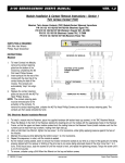
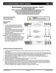
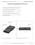
2100 SERIES/GEMINI USER’S MANUAL
VER. 1.2
Module & Contact Installation/Removal — Section 1
Twin Access Contact (TAC)
Receiver Wiring Module and ITA Module Installation/Removal Instructions
P/N 510 133 109 (380 signal wiring contacts)
P/N 510 133 110 (228 signal wiring contacts/12 coaxial or power wiring contacts)
P/N 510 133 111 (180 signal wiring contacts/10 coaxial (75 OHM) wiring contacts)
P/N 510 133 112 (46 coaxial or power wiring contacts)
P/N 510 134 104 (ITA, 46 positions, coaxial or power wiring contacts)
P/N 510 134 101 (ITA 380 signal wiring contacts)
P/N 510 134 102 (ITA, 228 positions/12 coaxial/power wiring contacts)
P/N 510 134 103 (ITA, 180 positions, 10 coaxial (75 OHM)
PARTS/TOOLS REQUIRED:
5/64 Allen Hex Wrench
3/32 Allen Hex Wrench
INSTRUCTIONS:
Receiver
1. Place the module on the rear of the Receiver Module aligning the
locating bosses on the modules with the appropriate holes in the
Receiver Module.
2. Install the modules such that the numbers can be read from top to
bottom, making them right side up.
3. Insert the #2 Socket Head Cap Screws, .50” length, in the module
fastening holes.
4. Using a 5/64 Allen Hex Wrench, tighten the top screw 1 to 2 full
revolutions, while lightly applying pressure against the face of the
module. 5. Maintain this pressure while tightening the bottom
screw 1 to 2 full revolutions.
6. Repeat this sequence until the module is seated. Torque the screw
until it is 4 to 5 inch pounds.
7. To remove, loosen the top screw 1 to 2 full revolutions. Loosen
bottom screw 1 to 2 full revolutions. Repeat this sequence until the
module is separated from the Receiver.
Receiver
Screened side of
Receiver Wiring
Module
NOTE: It is important to alternate the tightening/loosening of module screws.
ITA
1. To install Module into ITA, place module in the ITA with the screening facing
upward. Align top of the module with the designated top of the ITA and the
locating bosses on the module with the appropriate holes in the ITA.
2. The modules should be installed such that the numbers can be read from top
to bottom.
3. Insert the #4 Socket Head Cap Screws, 0.50” length, in the module fastening
holes.
4. Using a 3/32 Allen Hex Wrench, tighten the top screw 1 to 2 full revolutions,
while pushing lightly against the face of the module.
5. Maintain this pressure while tightening the bottom screw 1 t0 2 full revolutions.
6. Repeat this sequence until the module is seated. Torque the screw until it is 8
to 10 inch pounds.
To remove, loosen the screws until the module is separated from the ITA.
12 - VM2100_V1.2.pmd
www.vpc.com
ITA
Screened side of
ITA Wiring
Module
Virginia Panel Corporation