Transcript
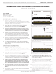
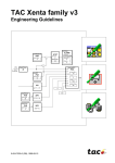
2100 SERIES/GEMINI USER’S MANUAL
VER. 1.2
Module Installation & Contact Removal Instructions— Section 1
Twin Access Contact (TAC)
Receiver Twin Access Contacts (TAC) Module/Contact Removal Insructions
P/N 510 133 101/102/103/104/105/106 (Receiver) Signal TAC
P/N 510 133 103/104/107/108 (Receiver) Coaxial TAC, 50 OHM
P/N 510 133 105/106 (Receiver) Coaxial TAC, 75 OHM
P/N 510 133 103/104/107/108 (Receiver) Power TAC
CAUTION
• DO NOT depress contacts with fingers.
PARTS/TOOLS REQUIRED:
5/64 Allen Hex Wrench
Phillips Head Screwdriver
INSTRUCTIONS:
Receiver
RECEIVER (TAC MODULE)
1.
To insert Contact into Module,
remove the contact retaining
plate from the bottom of the
STOP RING OF PIN ALWAYS
TOWARD RETAINING
module by unfastening the #2
PLATE
Flat Head Phillips Screws.
2. Insert contacts into the rear of the
module with the stop ring of the
contact facing the back of the
CONTACT RETAINING
PLATE
module. The contacts will
automatically “drop” into alignment.
3. Replace the contact retaining
COMPLETED TAC MODULE
plate and secure with two #2 Flat
Head Phillips Screws.
NOTE: The contact retaining plate
must be removed prior to the
extraction of the contacts. To
remove the contact retaining plate, unfasten the #2 Flat Head Phillips Screws and remove the contact retaining plate. The
contacts are then easily extracted by hand.
TAC (Receiver) Module Installation/Removal
1. To install a module into the Receiver, place the supplied hardware (#4 socket head cap screws), in the TAC Receiver Module.
2. Place the Module in the front of the Receiver aligning the locating pins on the module with the appropriate holes in the Receiver
Frame, so that the upper and lower module screws touch the mating holes on the Receiver Frame (install modules such that the
numbers can be read from top to bottom, making them right side up).
3. Using a 5/64 Allen Hex Wrench, tighten the top screw 1 to 2 full revolutions, while lightly applying pressure against the face of
the module.
4. Maintain this pressure while tightening the bottom screw 1 to 2 full revolutions.
5. Repeat this sequence, in order, until the module is seated.
6. As the module is being seated, watch to ensure that it does not become cocked at any time as a result of the guide pins not being
properly aligned with the receiver or binding of the pins due to one screw being advanced ahead of the other more than 1 to 2
turns. If this should occur, back the screws off until the module is level, and repeat the tightening process. Torque the screw until it
is 4 to 5 inch pounds
7. To remove, unfasten using a 5/64 Allen Hex Wrench on the top and bottom screws.
8 - VM2100_V1.2.pmd
www.vpc.com
Virginia Panel Corporation