Transcript
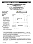
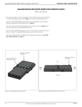
VIRGINIA PANEL CORPORATION
50 OHM COAXIAL CONTACTS AND MODULES USER’S MANUAL: SECTION 3
50 OHM COAXIAL RECEIVER CONTACT INSTALLATION AND REMOVAL
PART # 610 104 101 / 610 104 129 / 610 104 131
TOOLS REQUIRED
Power/Coaxial Receiver Extraction Tool, Part # 910 112 101
CONTACT INSTALLATION INSTRUCTIONS
1.
Assemble the contact to the respective wire.
NOTE: For more information concerning the process of crimping
the contact please see contact assembly instructions in Section 1
of this User’s Manual.
2.
Insert the terminated contact into the back (wiring side) of the
assembled module. The contact can only go into one side.
Once in place, pull the wire slightly to ensure that the contact is
seated.
CONTACT REMOVAL INSTRUCTIONS
1.
Remove the module from the receiver frame.
NOTE: For more information concerning the process of removing
the module from the receiver frame, see module installation and
removal instructions in Section 4 of this User’s Manual.
2.
Place the Power/Coaxial Receiver Extraction Tool, Part # 910
112 101 (Figure A), over the contact to be removed/replaced.
Use care to keep the tool perpendicular to the surface of the
module, otherwise the tool or the contact could be bent.
3.
Figure A. Power/Coaxial Receiver Extraction Tool, Part #
910 112 101.
Once the extraction tool is seated and the retaining ring tabs
on the contact are compressed, push the tool into the module
(Figure B). The contact will be pushed out of the rear of the
module.
DO NOT PUSH THE TOOL INTO THE MODULE UNTIL
THE TIP OF THE EXTRACTION TOOL HAS BEEN FULLY
SEATED INTO THE MODULE AND COMPRESSED THE
RETAINING RING TABS ON THE CONTACT.
NOTE: The process shown here uses standard/90 series modules. The
same process is used for modules from other series.
NOTE: If you are using a hybrid module, you may need to reference
the User’s Manual for the other contact type for extraction
instructions.
Figure B. Take care to keep the tool perpendicular to
prevent bent pins.
3-1
For more information visit vpc.com
10/4/13