1
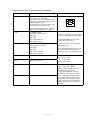
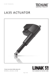
P R O D U C T D ATA S H E E T
ACTUATOR
LA25
Features:
• 12 or 24 V DC permanent magnetic motor
• Thrust from 900 N - 2500 N in push and pull
• Max. speed up to 13 mm/sec. depending on load
and spindle pitch
• Stroke length from 20 - 300 mm
• Protection class: IP66 (dynamic) and IP69K (static)
• Built-in endstop switches
• Guided nut
Options in general:
• Back fixture and piston rod eye material: Steel or stainless steel
• Safety nut in push or pull
(2500N version only safety nut in push)
• Exchangeable cables in different lengths up to 5 m
• Special anodised housing for extreme
environments
• Hall effect sensor
• Hall potentiometer
• IC options including:
- IC - Integrated Controller (H-bridge),
- Integrated Parallel Controller
- Modbus and LINbus communication
- Analogue or digital feedback for precise positioning
- Endstop signals
- PC configuration tool
Usage:
• Duty cycle: 20%, 2 minutes continuous use followed by 8 minutes not in use
•Ambient temperature: -40°C to +85°C,
full performance from +5°C to +40°C
With its robust design, high IP degree and
aluminium housing, the actuator LA25 is ideal for
harsh environments where operation under extreme
conditions is required. Furthermore, the compact
dimensions of the LA25 make it applicable for
confined spaces.
This TECHLINE® actuator comes with IC - Integrated controller.
For more information on our IC options, please see: www.linak.com/techline
Page 1 of 20
Contents
Chapter 1
Specifications............................................................................................................................... 3
Technical specifications............................................................................................................... 4
Stroke tolerances.......................................................................................................................... 4
Built-in tolerances........................................................................................................................ 4
LA25 Dimensions.......................................................................................................................... 5
Built-in dimensions....................................................................................................................... 5
LA25 Back fixture orientation.................................................................................................... 6
LA25 Piston Rod Eyes................................................................................................................... 6
Cable dimensions......................................................................................................................... 7
Speed and current curves........................................................................................................ 8-9
Chapter 2
I/O specifications:
Actuator without feedback............................................................................................... 10
Actuator with:
Endstop signal output ..................................................................................................... 10
Endstop signals and relative positioning -Single Hall...................................................... 11
Endstop signals and absolute positioning - Analogue feedback.................................... 12
Endstop signals and absolute positioning - PWM........................................................... 13
IC Basic............................................................................................................................. 14
IC Advanced - with BusLink........................................................................................ 15-16
Parallel.............................................................................................................................. 17
Chapter 3
Environmental tests - Climatic.............................................................................................. 18-19
Environmental tests - Mechanical............................................................................................... 19
Environmental tests - Electrical................................................................................................... 20
Non-complying standards.......................................................................................................... 20
Page 2 of 20
Chapter 1
Specifications
Motor:
Permanent magnet motor 12 or 24V DC
Cable:
Motor: 8 x 18 AWG PVC cable
Housing: The housing is made of casted aluminium, coated for outdoor use and in harsh conditions
Spindle part: Outer tube: Extruded aluminium anodised
Inner tube: Stainless steel AISI304/SS2333
Acme spindle: Trapezoidal spindle with high efficiency
Temperature range:
- 40o C to +85o C
- 40o F to +185o F
Full performance +5o C to +40o C
Storage temperature:
-55°C to +105°C
Weather protection: Rated IP66 for outdoor use. Furthermore, the actuator can be washed down with a high-pressure cleaner (IP69K).
Noise level:
58.5 dB (A) measuring method DS/EN ISO 8746 actuator not loaded.
Safety factor:
Static safety factor: 2.0
Compatibility:
The LA25 is compatible with SMPS-T160 (For combination possibilities,
please see the User Manual for SMPS-T160)
Be aware of the following two symbols throughout this product data sheet:
Recommendations
Failing to follow these instructions can result in the actuator suffering damage or being ruined.
Additional information
Usage tips or additional information that is important in connection with the use of the actuator.
Page 3 of 20
Technical specifications
LA25 with 12V motor
Type
Push/Pull
Max.
(N)
Self-lock min. (N)
Push/Pull
Without
With
short
short
circuit
circuit
2500
2500
25030xxxxxxxxA...
2500
25060xxxxxxxxA...
1500
1200
25090xxxxxxxxA...
1200
750
25120xxxxxxxxA...
900
750
Spindle
pitch
(mm)
*Typical speed
(mm/s)
No load
Full load
Standard
stroke
length
(mm)
*Typical amp. @
12 V
No load Full load
3
3.1
2.5
20 - 300
0.8
3.8
1500
6
6.6
5.2
20 - 300
0.8
3.8
1200
9
9.9
7.5
20 - 300
0.9
4.0
900
12
13
9.6
20 - 300
0.9
3.8
LA25 with 24V motor
Type
Push/Pull
Max.
(N)
25030xxxxxxxxB...
2500
Self-lock min. (N)
Push/Pull
Without
With
short
short
circuit
circuit
2500
2500
Spindle
pitch
(mm)
3
*Typical speed
(mm/s)
No load
Full load
3.2
2.6
Standard
stroke
length
(mm)
20 - 300
*Typical amp. @
24 V
No load Full load
0.4
1.9
25060xxxxxxxxB...
1500
1200
1500
6
6.4
5.5
20 - 300
0.4
1.9
25090xxxxxxxxB...
1200
750
1200
9
9.5
8.1
20 - 300
0.4
2.0
25120xxxxxxxxB...
900
750
900
12
12.6
10.4
20 - 300
0.4
1.9
*The typical values can have a variation of ± 20% on the current values and ± 10% on the speed values.
Measurements are made with an actuator in connection with a stable power supply and an ambient
temperature at 20°C.
•
Self locking ability
To ensure maximum self-locking ability, please be sure that the motor is shorted when stopped.
Actuators with integrated controller have this feature incorporated.
•
When using soft stop on a DC-motor, a short peak of higher voltage will be sent back towards the
power supply. It is important when selecting the power supply that it does not turn off the output,
when this backwards load dump occurs.
Stroke tolerances
Platform options
Descriptions
25XXXXXXXXXX0
25XXXXXXXXXX3
Stroke tolerance
Example for 200 mm stroke
With built-in limit switches
+ 2 / - 2 mm
198 to 202 mm
Integrated controller
+ 1 / - 3 mm
197 to 201 mm
Built-in tolerances
Platform options
Descriptions
BID tolerance
Example for 200 mm BID
25XXXXXXXXXXX
All variants
+ 2 / - 2 mm
198 to 202 mm
Page 4 of 20
LA25 Dimensions
Built-in dimensions
The built-in dimension depends upon the chosen safety option and stroke length.
Please see the table below to decide upon the built-in dimension.
Stroke length
Spindle pitch
Min. built-in
Dimensions
No safety option
20 - 49
6, 9 or 12
160
No safety option
20 - 49
3
168
Safety nut for push
20 - 49
6, 9 or 12
160
Safety nut for push
20 - 49
3
168
Safety nut for pull
20 - 49
6, 9 or 12
172
No safety option
50 - 200
6, 9 or 12
110 + stroke
No safety option
50 - 200
3
118 + stroke
Safety nut for push
50 - 200
6, 9 or 12
110 + stroke
Safety nut for push
50 - 200
3
118 + stroke
Safety nut for pull
50 - 200
6, 9 or 12
122 + stroke
No safety option
201 - 300
6, 9 or 12
130 + stroke
No safety option
201 - 300
3
138 + stroke
Safety nut for push
201 - 300
6, 9 or 12
130 + stroke
Safety nut for push
201 - 300
3
138 + stroke
Safety nut for pull
201 - 300
6, 9 or 12
142 + stroke
Safety option
Page 5 of 20
LA25 Back fixture orientation
Option 1 = 0°
Option 2 = 90°
LA25 Piston Rod Eyes
Piston: 0231016, Zinc coated
Piston: 0231095, Stainless steel AISI 304
Piston: 0231033, Zinc coated
Piston: 0231096, Stainless steel AISI 304
The Piston Rod Eye is only allowed to turn 0 - 90 degrees.
The Piston Rod Eyes can be mounted with extra bushes to reduce the hole to 10.1 or 8.1.
Page 6 of 20
Cable dimensions
Brown: Ø 1.0mm2
Blue: Ø 1.0mm2
Violet: Ø 1.0mm2
Black: Ø 1.0mm2
Red: Ø 1.0mm2
Yellow:Ø 1.0mm2
Green: Ø 1.0mm2
White: Ø 1.0mm2
AWG*: 18mm
AWG : 18mm
AWG : 18mm
AWG : 18mm
AWG : 18mm
AWG : 18mm
AWG : 18mm
AWG : 18mm
*AWG: American Wire Gauge
Brown: Ø 1.8mm
Blue: Ø 1.8mm
Violet: Ø 1.8mm
Black: Ø 1.8mm
Red: Ø 1.8mm
Yellow:Ø 1.8mm
Green: Ø 1.8mm
White: Ø 1.8mm
The LA25 standard cable is a UV resistant PVC cable.
Page 7 of 20
Speed and current curves - 12V motor
The values below are typical values and made with a stable power supply and an ambient temperature of 20˚C.
LA25 - 12V Speed vs Thrust
14
14
12
12
LA25 - 12V Speed vs Thrust
10
10
14
8
3mm pitch
12
6mm pitch
6
9mm pitch
10
Speed [mm/s]
Speed [mm/s]
14
12mm pitch
4
3mm pitch
2
6mm pitch
6
9mm pitch
0
500
1000
1500
2000
2500
3000
Speed [mm/s]
Speed [mm/s]
8
0
8
2
6
0
12mm pitch
4
Thrust [N]
LA25 - 12V Current vs Thrust
0
4,5 0
500
1000
1500
2000
0
2500
0
3000
2
Thrust [N]
4
1,8
3,5
1,6
LA25 - 12V Current vs Thrust
1,4
2,5
4
3mm pitch
6mm pitch
2
3,5
9mm pitch
1,6
0,8
3mm pitch
0,5
2
6mm pitch
9mm pitch
0
500
1000
1500
2000
2500
3000
Thrust [N]
1
12mm pitch
1,4
0,6
Current [A]
1
2,5
2
1,2
1,8
1
12mm pitch
1,5
3
0
1,5
Current [A]
3
4,5
Current [A]
0
2
2
Current [A]
6
10
4
4
8
12
1,2
0,4
1
0,2
0,8
0
0,6
0
0,4
0,5
0,2
0
0
500
1000
1500
2000
Thrust [N]
Page 8 of 20
2500
3000
0
0
0
Speed and current curves - 24V motor
The values below are typical values and made with a stable power supply and an ambient temperature of 20˚C.
LA25 - 24V Speed vs Thrust
14
12
3mm pitch
6mm pitch
9mm pitch
Speed [mm/s]
14
00
8
3mm pitch
12
6mm pitch
6
9mm pitch
10
12mm pitch
12mm pitch
3mm pitch
6mm pitch
9mm pitch
Speed [mm/s]
4
8
3mm pitch
2
6mm pitch
6
9mm pitch
0
12mm pitch
4
0
500
1000
1500
2000
2500
3000
LA25 - 1500
24V Current
vs Thrust
2000
2500
3000
12mm pitch
Thrust [N]
2
0
0
0
00
LA25 - 24V Speed vs Thrust
10
500
1000
2
Thrust [N]
1,8
1,6
LA25 - 24V Current vs Thrust
3mm pitch
6mm pitch
9mm pitch
Current [A]
1,4
12mm pitch
6mm pitch
9mm pitch
12mm pitch
1,8
1
3mm pitch
6mm pitch
1,6
0,8
9mm pitch
1,4
0,6
Current [A]
3mm pitch
2
1,2
12mm pitch
1,2
0,4
3mm pitch
1
0,2
6mm pitch
9mm pitch
0,8
0
0,6 0
500
1000
1500
2000
2500
3000
2000
2500
3000
Thrust [N]
0,4
0,2
0
0
500
1000
1500
Thrust [N]
Page 9 of 20
12mm pitch
Chapter 2
I/O specifications: Actuator without feedback
Input/Output
Specification
Comments
Description
Permanent magnetic DC motor.
Brown
12-24VDC (+/-)
To extend actuator:
Connect Brown to positive
12V ± 20%
24V ± 10%
Blue
To retract actuator:
Connect Brown to negative
Under normal conditions:
12V, max. 5A depending on load
24V, max. 2.5A depending on load
Red
Not to be connected
Black
Not to be connected
Green
Not to be connected
Yellow
Not to be connected
Violet
Not to be connected
White
Not to be connected
To extend actuator:
Connect Blue to negative
To retract actuator:
Connect Blue to positive
I/O specifications: Actuator with endstop signal output
Input/Output
Specification
Description
The actuator can be equipped with
electronically controlled endstop signals
out.
Brown
Comments
12-24VDC (+/-)
To extend actuator:
Connect Brown to positive
12V ± 20%
24V ± 10%
Blue
IN
OUT
To retract actuator:
Connect Brown to negative
Under normal conditions:
12V, max. 5A depending on load
24V, max. 2.5A depending on load
To extend actuator:
Connect Blue to negative
Red
Signal power supply (+)
12-24VDC
Black
Signal power supply GND (-)
Current consumption:
Max. 40 mA, also when the actuator is
not running
Green
Endstop signal out
Yellow
Endstop signal in
Violet
Not to be connected
White
Not to be connected
To retract actuator:
Connect Blue to positive
Output voltage min. VIN - 2V
Source current max. 100 mA
NOT potential free
Page 10 of 20
I/O specifications: Actuator with endstop signals and relative positioning - Single Hall
Input/Output
Specification
Comments
Description
The actuator can be equipped with Single
Hall that gives a relative positioning
feedback signal when the actuator moves.
Brown
12-24VDC (+/-)
To extend actuator:
Connect Brown to positive
12V ± 20%
24V ± 10%
Blue
To retract actuator:
Connect Brown to negative
Under normal conditions:
12V, max. 5A depending on load
24V, max. 2.5A depending on load
To extend actuator:
Connect Blue to negative
Red
Signal power supply (+)
12-24VDC
Black
Signal power supply GND (-)
Current consumption:
Max. 40 mA, also when the actuator is
not running
Green
Endstop signal out
Yellow
Endstop signal in
Violet
Single Hall output (PNP)
To retract actuator:
Connect Blue to positive
Output voltage min. VIN - 2V
Source current max. 100mA
NOT potential free
Movement per single Hall pulse:
LA25030 Actuator = 0.25mm per pulse
LA25060 Actuator = 0.5mm per pulse
LA25090 Actuator = 0.75mm per pulse
LA25120 Actuator = 1.0mm per pulse
Frequency:
Frequency is 10 - 20 Hz on Single Hall
output depending on load.
Pulse ON time is minimum 8ms. OFF time
between two ON pulses is minimum 8ms.
Overvoltage on the motor can result in
shorter pulses.
Diagram of Single Hall:
Hall A
N.B. For more precise measurements,
please contact LINAK A/S.
Low frequency with a high load.
Higher frequency with no load.
Single Hall output
Micro Processor
Hall B
White
Input
Output voltage min. VIN - 2V
Max. current output: 12mA
Max. 680nF
Fig. 1
Not to be connected
Page 11 of 20
I/O specifications: Actuator with endstop signals and absolute positioning - Analogue feedback
Input/Output
Specification
Comments
Description
The actuator can be equipped with electronic circuit that gives an analogue feedback signal when the actuator moves.
Brown
12-24VDC (+/-)
To extend actuator:
Connect Brown to positive
12V ± 20%
24V ± 10%
Blue
Red
To retract actuator:
Connect Brown to negative
Under normal conditions:
12V, max. 5A depending on load
24V, max. 2.5A depending on load
Signal power supply (+)
12-24VDC
Black
Signal power supply GND (-)
Green
Endstop signal out
Yellow
Endstop signal in
Violet
Analogue feedback
0-10V
To extend actuator:
Connect Blue to negative
To retract actuator:
Connect Blue to positive
Current consumption:
Max. 60 mA, also when the actuator
is not running
Output voltage min. VIN - 2V
Source current max. 100mA
NOT potential free
(Feedback level 1)
0.5-4.5V (Feedback level 2)
4-20mA (Feedback level 3)
Special (Feedback level 9)
Tolerances +/- 0.2 V
Max. current output: 1mA
Ripple max. 200mV
Transaction delay max. 20ms
Linear feedback 0.5%
Source current max. 1mA
Tolerances +/- 0.2mA
Transaction delay 20ms
Linear feedback 0.5%
Output: Source
Serial resistance:
12V max 300 ohm
24V max. 900 ohm
For all analogue feedbacks it is recommendable to have the actuator to activate
its limit switches on a regular basis, to ensure more precise positioning
White
Not to be connected
Page 12 of 20
I/O specifications: Actuator with endstop signals and absolute positioning - PWM
Input/Output
Specification
Comments
Description
The actuator can be equipped with
electronic circuit that gives an analogue
feedback signal when the actuator moves.
Brown
12-24VDC (+/-)
To extend actuator:
Connect Brown to positive
12V ± 20%
24V ± 10%
Blue
To retract actuator:
Connect Brown to negative
Under normal conditions:
12V, max. 5A depending on load
24V, max. 2.5A depending on load
To extend actuator:
Connect Blue to negative
Red
Signal power supply (+)
12-24VDC
Black
Signal power supply GND (-)
Current consumption:
Max. 40mA, also when the actuator is
not running
Green
Endstop signal out
Yellow
Endstop signal in
Violet
Digital output feedback
10-90%
White
To retract actuator:
Connect Blue to positive
Output voltage min. VIN - 2V
Source current max. 100 mA
NOT potential free
(Feedback level 4)
20-80%
(Feedback level 5)
Special
(Feedback level 9)
Not to be connected
Page 13 of 20
Output voltage min. VIN - 2V
Tolerances +/- 2%
Max. current output: 12mA
It is recommendable to have the
actuator to activate its limit switches
on a regular basis, to ensure more
precise positioning
I/O specifications: Actuator with IC Basic
Input/Output
Specification
Comments
Description
Easy to use interface with integrated
power electronics (H-bridge).
The actuator can also be equipped with
electronic circuit that gives an asolute or
relative feedback signal.
M
H-Bridge
The version with “IC option” cannot be
operated with PWM (power supply).
Brown
12-24VDC + (VCC)
Connect Brown to positive
Note: Do not change the power supply
polarity on the brown and blue wires!
12V ± 20%
24V ± 10%
Blue
12V, current limit 8A
24V, current limit 5A
Power supply GND (-) is electrically
connected to the housing
12-24VDC - (GND)
Connect Blue to negative
If the temperature drops below -10°C,
all current limits will automatically
increase to 9A for 12V, and 6A for 24V
12V ± 20%
24V ± 10%
12V, current limit 8A
24V, current limit 5A
Red
Extends the actuator
Black
Retracts the actuator
Green
Not to be connected
Yellow
Not to be connected
Violet
Analogue feedback
0-10V
On/off voltages:
> 67% of VIN = ON
< 33% of VIN = OFF
Input current: 10mA
(Feedback level 1)
Standby power consumption:
12V, 60mA
24V, 45mA
Ripple max. 200mV
Transaction delay 20ms
Linear feedback 0.5%
Max. current output: 1mA
It is recommendable to have the
actuator to activate its limit switches
on a regular basis, to ensure more
precise positioning.
Single Hall output (PNP)
White
Signal GND
Page 14 of 20
Output voltage min. VIN - 2V
Max. current output: 12mA
For more information see fig. 1, page
11
I/O specifications: Actuator with IC Advanced - with BusLink
Input/Output
Specification
Comments
Description
Easy to use interface with integrated
power electronics (H-bridge).
The actuator can also be equipped with
electronic circuit that gives an absolute or
relative feedback signal.
IC Advanced also provides a wide range
of possibilities for customisation.
M
H-Bridge
The version with “IC option” cannot be
operated with PWM (power supply).
Brown
12-24VDC + (VCC)
Connect Brown to positive
12V ± 20%
24V ± 10%
Power supply GND (-) is electrically
connected to the housing
12V, current limit 8A
24V, current limit 5A
Blue
12-24VDC - (GND)
Connect Blue to negative
Current limit levels can be adjusted
through BusLink
12V ± 20%
24V ± 10%
If the temperature drops below -10°C,
all current limits will automatically
increase to 9A for 12V, and 6A for 24V
12V, current limit 8A
24V, current limit 5A
Red
Note: Do not change the power supply
polarity on the brown and blue wires!
Extends the actuator
Black
Retracts the actuator
Green
Endstop signal out
On/off voltages:
> 67% of VIN = ON
< 33% of VIN = OFF
Input current: 10 mA
Output voltage min. VIN - 2V
Source current max. 100mA
Endstop signals are NOT potential
free. Endstop signals can be
configured with BusLink software
according to any position needed.
Yellow
Endstop signal in
Before configuring virtual endstop,
an absolute feedback type must be
chosen. Only use one virtual endstop
- keep one end open for initialisation.
(See I/O specifications for endstop on
page 10)
Page 15 of 20
I/O Specifications: Actuator with IC Advanced - with BusLink
Input/Output
Specification
Comment
Violet
Analogue feedback (0-10V):
Configure any high/low combination
between 0-10V
Ripple max. 200 mV
Transaction delay 20 ms
Linear feedback 0.5%
Max. current output. 1 mA
Single Hall output (PNP)
Output voltage min. VIN - 2V
Max. current output: 12mA
Please be aware that when choosing
single hall, feedback position readout
and virtual endstops are not available
in BusLink.
For more information, see fig. 1, page
11
Digital output feedback PWM:
Configure any high/low combination
between 0 - 100%
Output voltage min. VIN -2V
Frequency: 75Hz ± 10Hz as standard,
but this can be customised.
Duty cycle: Any low/high combination
between 0 and 100 percent.
Open Drain source current max. 12mA
Analogue feedback (4-20mA):
Configure any high/low combination
between 4-20mA
Tolerances +/- 0.2mA
Transaction delay 20ms
Linear feedback 0.5%
Output: Source
Serial resistance:
12 V max. 300 ohm
24 V max. 900 ohm
All absolute value feedbacks (0-10V, PWM
and 4-20mA)
Standby power consumption:
12V, 60mA
24V, 45mA
It is recommendable to have the
actuator to activate its limit switches
on a regular basis, to ensure more
precise positioning
White
Signal GND
BusLink is available for IC Advanced and can be used for:
Diagnostics, manual run and configuration.
Please note that the BusLink cables must be purchased separately from the actuator!
Item number for BusLink cables: 0147999
Page 16 of 20
I/O specifications: Actuator with Parallel
Input/Output
Specification
Comments
Description
Parallel drive of up to 8 actuators. A
master actuator with an integrated
H-bridge controller controls up to 7
slaves.
M
H-Bridge
M
H-Bridge
The version with “IC option” cannot be
operated with PWM (power supply).
Brown
12-24VDC + (VCC)
Connect Brown to positive
12V ± 20%
24V ± 10%
12-24VDC - (GND)
Connect Blue to negative
12V ± 20%
24V ± 10%
Red
H-Bridge
M
H-Bridge
Note: Do not change the power
supply polarity on the brown and blue
wires!
The parallel actuators can run on one
OR separate power supplies
12V, current limit 8A
24V, current limit 5A
Blue
M
Power supply GND (-) is electrically
connected to the housing
Current limit levels can be adjusted
through BusLink (only one actuator at
a time for parallel)
12V, current limit 8A
24V, current limit 5A
If the temperature drops below -10°C,
all current limits will automatically
increase to 9A for 12V, and 6A for 24V
Extends the actuator
On/off voltages:
> 67% of VIN = ON
< 33% of VIN = OFF
Input current: 10 mA
It does not matter where the in/out
signals are applied. You can either
choose to connect the signal cable
to one actuator OR you can choose
to connect the signal cable to each
actuator on the line. Either way this
will ensure parallel drive
Black
Retracts the actuator
Green
Endstop signal out
Yellow
Endstop signal in
Violet
Parallel communication:
Violet cords must be connected together
Output voltage min. VIN - 2V
Source current max. 100mA
NOT potential free
Standby power consumption:
12V, 60mA
24V, 45mA
No feedback available during parallel
drive
White
Signal GND:
White cords must be connected together
BusLink is available for Parallel and can be used for:
• Configuration and diagnostics
• Service counter is available with Parallel
Please note that the BusLink cables must be purchased separately from the actuator!
Item number for BusLink cables: 0147999
Page 17 of 20
Chapter 3
Environmental tests - Climatic
Test
Specification
Comment
TRD number
Cold test
EN60068-2-1 (Ab)
Storage at low temperature:
Temperature: - 40°C
Duration: 72 h
Actuator is not connected/operated
Tested at room temperature
TRD5675
Storage at low temperature:
Temperature: -55°C
Duration: 24 h
Actuator is not connected
Tested at room temperature
TRD5675
EN60068-2-1 (Ad)
Operating at low temperature:
Temperature: -40°C
Duration: 4 h
Tested at room temperature
within 5 minutes overload
EN60068-2-2 (Bb)
Storage at high temperature:
Temperature: +85°C
Duration: 72 h
Actuator is not connected/operated
Tested at room temperature
TRD5675
EN60068-2-2 (Bb)
Storage at low temperature:
Temperature: +105°C
Duration: 24 h
Actuator operated at high
temperature
TRD5675
Damp heat
EN60068-2-30 (Db)
Damp heat, Cyclic:
Relative humidity: 93 - 98 %
High temperature: +55°C in 12 hours
Low temperature: +25°C in 12 hours
Duration: 21 cycles * 24 hours
Actuator is operated during test
TRD5677
Salt mist.
EN ISO 9227
Dynamic salt spray test:
Salt solution: 5% sodium chloride
(NaCl)
Temperature: 35 ± 2°C
Duration: 500 h
Actuator is operated
TRD5678
Dunk test:
Actuator is heated to +85°C for 4 h
and submerged into a 0°C cold saltwater-detergent solution for 2 h
Followed by 18 h dry time
Duration: 5 cycles
TRD5679
Dry heat
Thermal shock
Page 18 of 20
Environmental tests - Climatic
Degrees of protection
EN60529 - IP66
IP6X - Dust:
Dust-tight, No ingress of dust
Actuator is not activated
TRD5680
EN60529 - IP66
IPX6 - Water:
Ingress of water in quantities
causing harmful effects is not allowed
Duration: 100 litres pr. minute in 3
minutes
Actuator is not activated
TRD5682
DIN40050 - IP69K
IPX9K: High pressure cleaner
Temperature: +80°C
Water pressure: 80 - 100 bar
Water flow: 14 - 16 l/min
Duration: 30 sec. each at 4 different
angles
0°, 30°, 60° and 90°
Actuator is not activated
Ingress of water in quantities causing
harmful effects is not allowed
TRD5680
Dynamic rain test:
Actuators exposed to continous rain
Actuators operated and side loaded
with 5N
Duration: 10.000 cycles and 240 h
TRD5681
Rain
Environmental tests - Mechanical
Test
Comment
TRD number
Mechanical Shock
(Handling) Drop test
3 drops on 6 faces onto a concrete floor.
Drop height: 500 mm on all faces
TRD5683
Mechanical Shock
Operational
Peak Pulse Amplitude: 50 G
Pulse Duration: 11 ms
Number of pulses: 18 total - 3 in each
direction for all three axis
TRD5684
Peak Pulse Amplitude: 30 G
Pulse Duration: 18 ms
Number of pulses: 18 total - 3 in each
direction for all three axis
TRD5684
Peak Pulse Amplitude: 25 G
Pulse Duration: 6 ms
Number of pulses: 6000 total - 1000 in
each direction for all three axis
TRD5684
Random vibration:
From 18 Hz 0.0259 to 1000 Hz
TRD5684
Vibration
Random
Specification
Duration: 2 h/axis
Page 19 of 20
Standard
Specification
FOCUS ON
2004/104/EC
Automotive EMC Directive 2004/104/EC on electrical
and electronic car components
•
VEHICLES AND
MOBILITY
EN/IEC 60204 - 1:
2006 + A1: 2009
Safety of machinery - Electrical equipment of
machines - Part 1: General requirements
•
INDUSTRIAL
AUTOMATION
EN/IEC 60204 - 32:
2008
Safety of machinery - Electrical equipment of
machines - Part 32: Requirements for hoisting
machines
•
INDUSTRIAL
AUTOMATION
PLATFORMS AND LIFTS
EN/IEC 61000 - 6 - 1:
2007
Electromagnetic compatibility (EMC) - Part 6-1:
Generic standards - Immunity for industrial environments
•
INDUSTRIAL
AUTOMATION
EN/IEC 61000 - 6 - 2:
2005
Electromagnetic compatibility (EMC) - Part 6-2:
Generic standards - Immunity for industrial environments
•
INDUSTRIAL
AUTOMATION
EN/IEC 61000 - 6 - 3:
2007 + A1:2011
Electromagnetic compatibility (EMC) - Part 6-3:
Generic standards - Emission standard for residential,
commercial and light-industrial environments
•
INDUSTRIAL
AUTOMATION
EN/IEC 61000 - 6 - 4:
2007 + A1:2011
Electromagnetic compatibility (EMC) - Part 6:
Generic standards - Section 4: Emission standard for
industrial environments
•
INDUSTRIAL
AUTOMATION
EN 13309: 2010
Construction machinery
•
CONSTRUCTION
EN/ISO 13766:
2006
Earth-moving machinery - Electromagnetic
compatibility
•
CONSTRUCTION
EN/ISO 14982:
2009
Agricultural and forestry machines Electromagnetic compatibility
•
•
MOBILE AGRICULTURE
OUTDOOR POWER
EQUIPMENT
•
EU recreational crafts
directive
94/25/EC
Non-complying standards
Standard
Explanation
IEC 60601-1
Please note that this product cannot be approved according to the medical electrical
equipment standard. Due to the combination of the aluminium cast housing and the
embedded PCB, we do not fulfill the regulations according to leakage current.
Terms of use
The user is responsible for determining the suitability of LINAK products for specific application.
LINAK takes great care in providing accurate and up-to-date information on its products.
However, due to continuous development in order to improve its products, LINAK products are
subject to frequent modifications and changes without prior notice. Therefore, LINAK cannot
guarantee the correct and actual status of said information on its products.
While LINAK uses its best efforts to fulfil orders, LINAK cannot, for the same reasons as
mentioned above, guarantee the availability of any particular product. Therefore, LINAK reserves
the right to discontinue the sale of any product displayed on its website or listed in its catalogues
or other written material drawn up by LINAK.
All sales are subject to the Standard Terms of Sale and Delivery for LINAK. For a copy hereof,
please contact LINAK.
FOR MOUNTING INSTRUCTIONS AND GUIDANCE IN USAGE, PLEASE SEE THE RELEVANT USER’S MANUALS
Copyright © LINAK 2015.11 . MA M9-02-522-F . Chapter 5.21
Environmental tests - Electrical