1
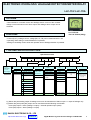
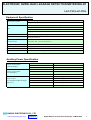
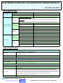
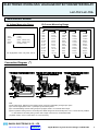
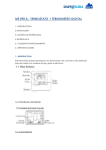
PRODUCT CATALOG
ELECTRONIC OVERLOAD/ LEAKAGE DETECTION METER RELAY
LLC-110/ LLC-110L
ELECTRONIC OVERLOAD/ LEAKAGE DETECTION METER RELAY
LLC-110/ LLC-110L
OUTLINE
* Most suitable for overload monitor and leakage electric current of the constant
voltage circuit.Overload current alarm output and leakage alarm output can be
extracted.
LLC-110/110L
FEATURES
110*110*105mm (600g)
* Current (R,S,T), leakage current, voltage (RS, ST, TR) can be measured with 1 unit.
* Operating value setting of overload detection is possible.
* Setting for sensibility current value and operation time of leakage detection is possible.
TYPE AND SPECIFICATION CODE
Specification Code
Type
LLC-110
No Backlight
LLC-110L
With Backlight
―
A
3) Input Circuit
(3)
4) Input Range
2 1Φ 3W
1Φ 3W
3 3Φ 3W
J 150-300, 5A, ZCT
K 150-300, 1A, ZCT
(4)
5) Auxiliary Power
AC85 - 253V
1 DC80 - 143V
For both us e
2 DC20 - 56V
Z
(5)
(6)
6) External Operation
Input
―
(7)
7) Analog Output
*(1)
0 None
0 No Analog
1 Dis play Change
1 4 - 20m A
2 Res et
2 0 - 1m A
Dis play Change
3
+ Res et
3 1 - 5V
Except Above
(8)
(9)
8) Puls e Output
0 None
1 output a contact
1 (Photo MOS relay)
*(2)
9) Alarm Output
1
1 output a contact
leakage (relay)
2
2 output a contact
for each (relay)
*(1), *(2)
Z
Except Above
4 0 - 5V
5 0 - 10V
3Φ 3W
J 150V, 5A, ZCT
K 150V, 1A, ZCT
L 300V, 5A, ZCT
M 300V, 1A, ZCT
Z
Except Above
Z
Except Above
Z
Except Above
Z
Except Above
Z
Analog output
Except Above
Z
Except Above
Note:
*(1) Meter relay with analog output of leakage current can be manufactured. Alarm output = 1 output of leakage only.
*(2) Meter relay with pulse (Wh) output can be manufactured with following combination.
Pulse (Wh) output + alarm (leakage 1 output) + external operation input (reset)
Pulse (Wh) output + alarm (leakage 1 output)
DAIICHI ELECTRONICS CO., LTD
http://www.daiichi-ele.co.jp
Product List
Digital Measuring Instrument Catalogue e-FB98-098a
2
ELECTRONIC OVERLOAD/ LEAKAGE DETECTION METER RELAY
LLC-110/ LLC-110L
Equipment Specification
C o n n e ctin g s ys te m
In p u t, a u xilia ry p o w e r p a rt M4 s cre w
Ou tp u t, d is p la y ch a n g e in p u t p a rt M3 s cre w
LC D
Ma in m o n ito r : C h a ra cte r h e ig h t 1 1 m m
4 d ig its
S u b m o n ito r (L ): C h a ra cte r h e ig h t 6 m m
4 d ig its
S u b m o n ito r (R ): C h a ra cte r h e ig h t 6 m m
4 d ig its
B a r g ra p h : 3 0 d o ts
D is p la y u p d a te tim e
Ap p ro x. 1 s e c. (Ba r g ra p h : Ap p ro x. 0 .2 5 s e c.)
Me a s u re m e n t
Th re e p h a s e cu rre n t, le a ka g e cu rre n t, th re e p h a s e vo lta g e , o ve rlo a d d e te ctio n ,
le a ka g e d e te ctio n
Op e ra tin g te m p e ra tu re /
h u m id ity ra n g e
-1 0 to +5 5 °C ,
3 0 to 8 5 % R H
Sto ra g e te m p e ra tu re ra n g e
-2 5 to +7 0 °C
Ma te ria l
AB S (V-0 )
Ma s s
600g
S ize
R e fe r to o u tlin e d ra w in g (C o m p a tib le w ith w id e a n g le in d ica to r)
(N o co n d e n s a tio n )
E xte rio r co lo r: B la ck (Mu n s e ll N 1 .5 )
Auxiliary Power Specification
Pow e r co ns u m ptio n
( With b acklig ht )
Pow e r co ns u m ptio n
( N o b ackligh t )
R us h curre nt
( Fo r ba ckligh t & N o ba ckligh t
both us e )
AC 85 - 2 53V 50/60 H z
10VA
D C 8 0 - 14 3V
5W
D C 2 0 - 56 V
6W
AC 85 - 2 53V 50/60 H z
8VA
D C 8 0 - 14 3V
4W
D C 2 0 - 56 V
5W
AC 110V
5.3A or le s s (App ro x. 1.6m s )
AC 220V
10.5A o r les s (Ap prox. 1.6m s )
D C 1 10V
3.7A or le s s (App ro x. 1.6m s )
D C 2 4V
5.0A or le s s (App ro x. 2.0m s )
D C 4 8V
9.9A or le s s (App ro x. 2.0m s )
DAIICHI ELECTRONICS CO., LTD
http://www.daiichi-ele.co.jp
Product List
Digital Measuring Instrument Catalogue e-FB98-098a
3
ELECTRONIC OVERLOAD/ LEAKAGE DETECTION METER RELAY
LLC-110/ LLC-110L
Input Specification
Input power
cons um ption VA
Voltage circuit rated value: 110V (FS: 150V)
0.25VA or les s
Voltage circuit rated value: 220V (FS: 300V)
0.5VA or les s
Current circuit: 5A, 1A
0.1VA or les s
Input
s pecification
External operation Power
(Dis play change) cons um ption
Contact
capacity
Power
cons um ption
Res et input
Contact
capacity
Indication res huffling input: Indication res huffling is pos s ible by adding a voltage s ignal,
function s am e as a DISPLAY s witch.
Res et input: The m ax. and m in., res et of the warning output are pos s ible by adding a
voltage s ignal.
Rating s am e as the auxiliar power , im pres s s m alles t puls e width 300m s continuation.
AC, DC100/110V
0.4VA, 0.4W
AC200V/220V
1.4VA
DC24V
0.3W
DC48V
1.2W
AC, DC100/110V
3m A
AC200V/220V
6m A
DC24V
10m A
DC48V
20m A
AC, DC100/110V
0.4VA, 0.4W
AC200V/220V
1.4VA
DC24V
0.3W
DC48V
1.2W
AC, DC100/110V
3m A
AC200V/220V
6m A
DC24V
10m A
DC48V
20m A
Output Specification
Analog output: 1 circuit
Res pons e tim e
4-20m A: 550Ω or les s , 0-1m A: 10kΩ or les s
1-5V: 600Ω or m ore, 0-5V: 600Ω or m ore
0-10V: 2kΩ or m ore
1 s ec. or les s . Tim e to be within ±1 % of final cons tant value
Output ripple
Les s 1% p-p agains t output s pan
Rated value
Ala rm output Output e le ment: Ove rloa d a la rm, lea ka ge alarm
Output s ys tem
Non-voltage
1a contact
Contact capacity
AC250V 8A, DC125V 0.3A (Res is tance load)
AC250V 2A, DC125V 0.1A (Inductive load)
Pulse output: Output e le ment: w att-hour
Output s ys tem
Photo MOS - FET relay
1a contact
Contact capacity
AC, DC125V 70m A (Res is tance load, Inductive load)
250m s ±10%
Puls e width
In the cas e of the output puls e cycle at the ratings electric power becom es the s peed of two
puls es / s econd or m ore according to ranges s etting (the voltage m eas urem ent range, the current
m eas urem ent range, and output puls e unit range), the output puls e width becom es 100 to 130m s .
Output puls e cycle = rated power [ kW]/ output puls e unit [kWh/ puls e]/ 3600 s ec.
Refer to Page 11 for output puls e unit s etting.
Output ON res is tance
10Ω ٛor les s
DAIICHI ELECTRONICS CO., LTD
http://www.daiichi-ele.co.jp
Product List
Digital Measuring Instrument Catalogue e-FB98-098a
4
ELECTRONIC OVERLOAD/ LEAKAGE DETECTION METER RELAY
LLC-110/ LLC-110L
PERFORMANCE
Measuring
element
Item
Current
Digital
display
Allowance *(3)
Measuring range/ Display specification
AC5.00A - 8.00kA (60 range)
Leakage max. current, leakage current
Leakage current
AC0.05A - 0.8A (5 range)
Voltage
AC150V - 600V (5 range)
Output
±1.0%
―
±10%
±10%
±1.0%
―
Watt-hour Power integrating (only power receiving). Only pulse output.
Bar graph display
Main monitor
Display
setting
potential
element
―
Power factor 1: ±2.0%
power factor 0.5: ±2.5%
R-S-T phase change *(4)
% against rated sensitivity current value
0 display when input is 5mA or less
RS-ST-TR line change *(5)
Ordinary watt-hour meter performance conformity,
Refer to common specification (Page11) for setting
range of pulse output unit (kWh/ pulse)
Bar graph display of main monitor elements. Sub-monitor elements can be displayed by setting.
Current, leakage current, voltage, overload characteristics (setting value), overload operating value (setting value)
Sub-monitor (L) Current, leakage current, leakage max. current, leakage sensitivity current value (setting value), voltage
Sub-monitor (R) Current, leakage current, leakage operation time (setting value), voltage
Bar graph
Overload
detection *(6)
Alarm
output
contact
Leakage
detection
Option
Note
Display
Current, leakage current, leakage max. current, voltage
Operation
characteristics
Cold start characteristics: Detection within 2 - 30sec. through 600% current of setting current.
Hot start characteristics: Detection within 2 hours through 125% current of setting current.
: Detection within 4 min. through 200% current of setting current.
Setting range
2.5A - 6A (0.1A step), with function exclusion setting index display setting in primary current
Detection
characteristics
Detection speed change in 5 steps (A-E)
Reset system
Automatic or manual (setting)
Output contact
Non-voltage a contact
Test function
Trip function test of overload detection is possible in test mode.
R phase or T phase detection
Function
Leakage current measured value ≧ rated sensitivity current value: Alarm display, output
Setting accuracy
-50% to 0% (% against sensitivity current value)
Rated sensitivity
current value
0.05A/ 0.1A/ 0.2A/ 0.4A /0.8A
Operation time
0.1 sec. (high-speed type), 0.3sec./ 0.5sec./ 1sec./ 2sec. (time delay type), function exclusion
Reset system
Automatic or manual (setting)
Output contact
Non-voltage a contact
Test function
Test function check of leakage current detection is possible in test mode.
Reset input (overload detection, leakage max. current measured value, leakage detection), display change input, leakage current analog output, watt-hour pulse output
Note:
*(3) Due to the measurement system of the meter, the accuracy will decrease if the meter directly measures the output of
cycle control inverters, phase-angle-control SCR inverters and PWM control inverters.
*(4) Single phase 3 wire: RN-TN-RT
*(5) Single phase 3 wire: R-T-N
*(6) When with leakage current analog output: Display only and overload detection output is not possible.
DAIICHI ELECTRONICS CO., LTD
http://www.daiichi-ele.co.jp
Product List
Digital Measuring Instrument Catalogue e-FB98-098a
5
ELECTRONIC OVERLOAD/ LEAKAGE DETECTION METER RELAY
LLC-110/ LLC-110L
MEASURING RANGE
A) Voltage Measuring Range
150V
150.0V
300V
300.0V
600V
(110V)
(110V)
(220V, VT220/110V)
(220V, VT220/110V)
(VT440V/110V)
For single phase 3 wire: only 150V, 150.0V.
B) Current Measuring Range
5. 00A
6. 00A
7. 50A
8. 00A
10. 00 A
10. 0A
12. 00 A
12. 0A
15. 00 A
15. 0A
20. 00 A
20. 0A
25 .0 0A
25 .0 A
30 .0 0A
30 .0 A
40 .0 A
50 .0 A
60 .0 A
75 .0 A
80 .0 A
10 0. 0A
10 0A
12 0. 0A
1 20A
1 50. 0A
1 50A
2 00. 0A
2 00A
2 50. 0A
2 50A
3 00. 0A
3 00A
4 00A
5 00A
6 00A
750 A
800 A
100 0A
1. 00k A
120 0A
1. 20k A
150 0A
1. 50k A
200 0A
2. 00k A
250 0A
2. 50k A
300 0A
3. 00k A
400 0A
4. 00k A
500 0A
5. 00k A
600 0A
6. 00k A
750 0A
7. 50k A
800 0A
8. 00k A
Connection Diagram (10)
Note:
(6) Wh pulse output, leakage current analog output, reset input and display change input: option
(7) In case of single phase 3 wire: S phase(no.7) becomes N phase.
(8) In case that leakage current analog output is equipped, there is no overload alarm output.
(9) Do not perform earth ground on secondary ZCT. Make wiring from the secondary ZCT to LLC-110 as short as possible.
In case that ZCT secondary wiring comes near to large current circuit, use shielded cable.
(10) When used in 110V or 220V direct, VT is not necessary.
DAIICHI ELECTRONICS CO., LTD
http://www.daiichi-ele.co.jp
Product List
Digital Measuring Instrument Catalogue e-FB98-098a
6
ELECTRONIC OVERLOAD/ LEAKAGE DETECTION METER RELAY
LLC-110/ LLC-110L
Outline Drawing (unit: mm)
ZCT Outline Drawing
DAIICHI ELECTRONICS CO., LTD
http://www.daiichi-ele.co.jp
Product List
Digital Measuring Instrument Catalogue e-FB98-098a
7
ELECTRONIC OVERLOAD/ LEAKAGE DETECTION METER RELAY
LLC-110/ LLC-110L
OVERLOAD OPERATION CHARACTERISTICS
O v erload O perat ion Charac teris tic
(Cold St art Charac teris tics )
Ov erload Operat ion Charac teris tic
(Hot Start C harac teris tic s)
( mi n )
( mi n)
50
50
10
10
5
5
Ope ra ted
T ime
Ope ra ted
Tim e
(se c )
(s ec)
30
30
E ( sl ow 2 )
10
10
5
5
D (sl o w 1 )
E (sl ow 1)
C (norm a l)
D ( sl ow 2)
B (fast 1 )
1
C (norm al )
1
0.5
A (fast 2 )
0. 5
B (fast 1)
A (fast 2)
0 .1
0.1
1
1.05
2
5
10
Mult iple of Sett ing C urrent
1
1. 05
2
10
5
Mult iple o f Set t ing C urrent
ITEM TO SPECIFY WHEN PURCHASE
* Specify for product type, specification and units require.
* Example of specify:
Refer to page 1 for specification code.
Type
LLC-110
Specification Code
L
―
↑
No Backlight
With Backlight
Blank
L
A
3
J
1
↑
↑
↑
↑
Auxiliary
Power
Hard
Model
Input
Circuit
Input
Range
2
―
0
1
1
↑
↑
↑
↑
External
Operation
Input
Analog
Output
Pulse
Output
Alarm
Output
1. Change from initial setting can be accepted with compensation. Specify the items to change.
Refer to page 14 - initialization value.
2. Have a consultation with us for specification which is not in specification code.
DAIICHI ELECTRONICS CO., LTD
http://www.daiichi-ele.co.jp
Product List
Digital Measuring Instrument Catalogue e-FB98-098a
8
ELECTRONIC OVERLOAD/ LEAKAGE DETECTION METER RELAY
LLC-110/ LLC-110L
NAME AND THE FUNCTION OF EACH PART
Bar graph display
Digital display
Indicate main monitor measurement value.
Measurement value for the sub-monitor is
possible by setting. Bar graph will display
at below the setting digital.
3 elements can be measured and monitored concurrently.
Sub-monitor (L)
Main monitor
Sub-monitor (R)
Light of OVERLOAD will ON when
overload is detection.
Light of LEAKAGE will ON when
leakage current is detection.
Scale number
SET
Set automatically by measuring
range setting.
This switch is used to select the setting
mode. Display mode will be change to setting mode when continuously press ON
more then 3 sec. This switch is used to
set value in the setting mode.
Upper limit setting index
Upper limit setting value is indicated.
When the bar-graph is voltage,
-
flicker setting value is indicated.
This switch is used to confirm overload detection setting value, leakage detection
setting value, voltage flicker value. This
switch also used to carry down set value
in setting mode. If not operated for 10 sec.
operated mode will return back to display
mode.
Unit display
Set automatically by measuremant
range setting.
DISPLAY
+
This switch is used for change main monitor measuring elements.
Current (R)
Current (S)
Current (T)
Leakage current
Voltage (RS)
Voltage (ST)
Voltage (TR)
measurement
change by this order. This function can be replaced by DISPLAY switch
for setting and also can used for carry up a set value in setting mode. If
not operated for 10 min. display mode will return back to settig being
completed display pattern.
This switch is used for change over the current, voltage phase (lines). After 1 action setting, mode display will return back to display mode. If not operated
for 10 min. display pattern will return back to setting
being completed display pattern. This function can
be replaced by + switch for setting.
RESET/SHIFT
Max. leakage current and output of overload/
leakage detection can reset by press ON more
than 1 sec. continuously. This switch also used
to shift an item in the setting mode
DAIICHI ELECTRONICS CO., LTD
http://www.daiichi-ele.co.jp
Product List
Digital Measuring Instrument Catalogue e-FB98-098a
9
ELECTRONIC OVERLOAD/ LEAKAGE DETECTION METER RELAY
LLC-110/ LLC-110L
SETTING
Refer to attached user's manual for setting method details.
SETTING-2
SETTING-1
SET and DISPLAY
SET 3s
DISPLAY
3s
RESET/SHIFT and +
Display
mode
DISPLAY
RESET/SHIFT and +
RESET/SHIFT and -
RESET/SHIFT and +
Display
mode
RESET/SHIFT and -
Leakage detection setting
DISPLAY
RESET/SHIFT and -
RESET/SHIFT and -
Overload detection setting
DISPLAY
DISPLAY switch function change
setting
RESET/SHIFT and +
Measurement range setting
RESET/SHIFT and +
RESET/SHIFT and -
Voltage flicker value setting
RESET/SHIFT and +
DISPLAY
DISPLAY
Display combination setting
RESET/SHIFT and -
Display dead band setting
DISPLAY
RESET/SHIFT and +
Refer to page 13 for display combination (pattern).
RESET/SHIFT and -
Measurement display
ON/OFF setting
DISPLAY
RESET/SHIFT and +
RESET/SHIFT and -
Input circuit change setting
DISPLAY
RESET/SHIFT and +
DISPLAY
RESET/SHIFT and -
Return to initial set value
RESET/SHIFT and +
RESET/SHIFT and -
DAIICHI ELECTRONICS CO., LTD
http://www.daiichi-ele.co.jp
Product List
Digital Measuring Instrument Catalogue e-FB98-098a
10
ELECTRONIC OVERLOAD/ LEAKAGE DETECTION METER RELAY
LLC-110/ LLC-110L
LC-110 SERIES COMMON SPECIFICATION
Approved Standard/ Pulse Output/ Intensity
Electronic m ulti
m eter
Electronic
harm onics
m eter relay
Electronic
dem and m ulti
m eter
Electronic
m ax./ m in.
m ulti m eter
Electronic
overload/ leakage
detection m eter
relay
Electronic
three phas e
current m eter
Electronic
three phas e
voltage
m eter
Electronic
DC receiving
m eter
Electronic
DC input
m eter
No
backlight
QLC-110
HLC-110
DLC-110
MLC-110
LLC-110
ALC-110
VLC-110
XLC-110
TLC-110
W ith
backlight
QLC-110L
HLC-110L
DLC-110L
MLC-110L
LLC-110L
ALC-110L
VLC-110L
XLC-110L
TLC-110L
Item
Type
JIS C 1102
JIS C 1102
JIS C 1102
JIS C 1102
-1, -2, -3, -4, -5, -7
-1, -2, -7
-1, -2, -3, -5, -7
-1, -2, -7
JIS C 1111
JIS C 1111
JIS C 1111
JIS C 1111
JIS C 1216
Perform ance JIS C 1216
Perform ance
Approved standard
JIS C 1263
conform ed Perform ance
conform ed
Perform ance
conform ed
EIA s tandard
conform ed
EIA s tandard
RS-485
EIA s tandard
RS-485
RS-485
Output
element
Watt-hour OR
Watt-hour
var-hour
*Output s ys tem : Photo MOS - FET relay 1 a contact.
Output ON res is tance: 10Ω or les s .
-
JIS C 1102
-1, -2, -7
JIS C 1111
JIS C 8325
JIS C 8374
JIS C 1216
Perform ance
conform ed
JIS C 1102
JIS C 1102
JIS C 1102
JIS C 1102
-1, -2, -7
-1, -2, -7
-1, -2, -7, -9 -1, -2, -7, -8, -9
JIS C 1111
JIS C 1111
JIS C 1111
JIS C 1111
Perform ance Perform ance JIS C 1010-1 JIS C 1010-1
conform ed
conform ed Perform ance Perform ance
conform ed
conform ed
EIA s tandard EIA s tandard
Discontinued Model
(since December 31,2011).
RS-485
RS-485
Watt-hour
-
-
-
-
Contact capacity: AC, DC125V 70m A (res is tance load, inductive load)
*Puls e width: 250m s ±10% (There is a cas e of 100 - 130m s by range s etting.)
When the output puls e cycle at the rated electric power becom es the s peed of 2 puls es or m ore per s econd by s etting voltage m eas urem ent
range, current m eas urem ent range, and output puls e unit, the output puls e width becom es 100 - 130m s .
*Output puls e cycle = Rated electric power [kW] / output puls e unit [kWh / puls e] / 3600 [s ec.]
For exam ple: when voltage m eas urem ent range: 9000V (6600V / 110V), current range: 80.0A (80A / 5A), output puls e unit: 0.1 kWh / puls e
rated electric power = 1kW × (6600 / 110V) × (80 / 5A) = 960 [kW]
output puls e cycle = 960 [kW] / 0.1 [kWh / puls e] / 3600 [s ec.] = 2.667 puls e / s ec.
puls e width becom es 100 - 130m s .
*Output puls e unit can be s et in following range. Output puls e unit is not changed by changing m eas uring range.
Pulse
output
Outout
pulse
constant
Three phas e 3 wire / Three phas e 4 wire: Full load power (kW, kvar) = √ 3 × rated voltage (V) × rated current (A) × 10 -3
Single phas e 3 wire
: Full load power (kW, kvar) = 2 × rated voltage (V) × rated current (A) × 10 -3
Single phas e
: Full load power (kW, kvar) = Rated voltage (V) × rated current (A) × 10 -3
Full load power (kW, kvar)
Below1
1 or m ore
Below 10
10 or m ore
Below 100
100 or m ore
Below 1000
1,000 or m ore
Below 10,000
10,000 or m ore
Below 100,000
100,000 or m ore
Below 1,000,000
Multiplying
factor
Output puls e unit kWh (kvarh) / puls e
0.1
0.01
0.001
0.0001
1
0.1
0.01
0.001
10
1
0.1
0.01
100
10
1
0.1
1,000
100
10
1
10,000
1,000
100
10
100,000
10,000
1,000
100
0.01 *(1)
0.1
1
10
100
1,000
10,000
(1) Applied to only DLC-110/110L. Even though multiplying factor is 0.01, multiplying factor display is 0.1
(integer digit: 4 digits display, expansion display: 4 digits after decimal point.)
DAIICHI ELECTRONICS CO., LTD
http://www.daiichi-ele.co.jp
Product List
Digital Measuring Instrument Catalogue e-FB98-098a
11
ELECTRONIC OVERLOAD/ LEAKAGE DETECTION METER RELAY
LLC-110/ LLC-110L
LC-110 SERIES COMMON SPECIFICATION
Approved Standard/ Pulse Output/ Intensity
(1) Voltage circuit: 2 times of rated voltage (10s ec.)
Overload
capacity
1.2 times (continuity)
(2) Current circuit: 40 times of rated current (1s ec.), 20 times (4sec.), 10 times (16s ec.), 1.2 tim es (continuity)
(3) Auxiliary power: 1.5 times of rated voltage (10 sec.), 1.2 times (continuity), 1.5 times of rated voltage at DC100/ 110 (10 s ec.), 1.3 tim es
(continuity)
(4) DC input circuit (4 to 20mA): 10 times of rated current (5s ec.), 1.2 times (continuity)
(1) Between electrical system and cas e (ground)
DC500V 50MΩ or more
(2) Between input, output and auxiliary power
DC500V 50MΩ or more
(3) Between analog output and puls e output
DC500V 50MΩ or more (QLC, DLC, LLC)
(4) Between analog output and alarm output
DC500V 50MΩ or m ore (HLC, DLC, MLC, LLC)
(5) Between communication output and puls e output
Insulation
(6) Between communication output and alarm output
resistance
(7) Between pulse output and alarm output
DC500V 50MΩ or more (QLC, DLC)
DC500V 50MΩ or more (DLC,MLC)
DC500V 50MΩ or more (DLC,LLC)
(8) Between alarm output 1 and alarm output 2
DC500V 50MΩ or more (HLC,LLC)
(9) Between DC input (4 to 20mA), AC input and auxiliary power
DC500V 50MΩ or more (QLC with DC input)
(10) Between DC input
DC500V 50MΩ or more (XLC,TLC)
(11) Non-insulation by minus common between analog output.
(QLC, DLC, HLC, XLC, TLC, MLC)
(1) Between electrical system and cas e (ground)
AC2000V 50/ 60 Hz 1 min.
(2) Between input, output and auxiliary power
AC2000V 50/ 60 Hz 1 min.
(3) Between analog output and puls e output
AC1500V 50/ 60 Hz 1 min. (QLC, DLC, LLC)
(4) Between analog output and alarm output
AC1500V 50/ 60 Hz 1 min. (HLC, DLC, MLC, LLC)
(5) Between communication output and puls e output
AC1500V 50/ 60 Hz 1 min. (QLC, DLC)
Withstand
(6) Between communication output and alarm output
voltage
(7) Between pulse output and alarm output
Strength
AC1500V 50/ 60 Hz 1 min. (DLC, MLC)
AC1500V 50/ 60 Hz 1 min. (DLC, LLC)
(8) Between alarm output 1 and alarm output 2
AC1500V 50/ 60 Hz 1 min. (HLC, LLC)
(9) Between DC input (4 to 20mA), AC input and auxiliary power
AC2000V 50/ 60 Hz 1 min. (QLC with DC input)
(10) Between DC input
AC2000V 50/ 60 Hz 1 min. (XLC, TLC)
(11) Non-insulation by minus common between analog output.
(QLC, DLC, HLC, XLC, TLC, MLC)
(1) Between electrical system (analog output or communication output excluded) and ground
6kV 1.2/ 50µs pos itive/ negative polarity
3 times for each (QLC, DLC)
Lightning (2) Between electrical system (DC input 4 to 20mA excluded) and ground
impulse
5kV 1.2/ 50µs pos itive/ negative polarity
3 times for each
withstand (3) Between analog output or com munication output and ground
voltage
5kV 1.2/ 50µs pos itive/ negative polarity
3 times for each (QLC,DLC)
(4) Between auxiliary power and ground
7kV 1.2/ 50µs pos itive/ negative polarity
3 times for each (LLC)
(1) Oscillatory surge voltage
1 to 1.5MHz peak voltage: When attenuated oscillatory waveform (2.5 to 3kV) is applied repeatedly:
Measured error: within 10% (power circuit, AC voltage circuit, AC current circuit,
XLC, TLC: DC voltage/ current circuit)
No communication error/ communication halt
(2) Square-wave impulse noise
Nois e (1µS, 100ns width) is repeatedly applied for 5 min. : Measured error is within 10%
AC voltage/ AC current circuit (normal/ common) 1.5 kV or more
Power circuit (normal/ common)
1.5 kV or more
Noise
Puls e output (common)
1.0 kV or more
Alarm output (common)
1.0 kV or m ore
capacity
Operation input (common)
1.0 kV or more
Analog output (Inductive)
1.0 kV or more
Com munication output (Inductive)
1.0kV or more
(3) Radio nois e: When radion wave (150, 400, 900MHz) is applied (5W, 1m) intermittently: Measured error is within 10%
(4) Electros tatic nois e: At the passage of electric current 8kV Measured error : within 10%
At no pass age of electric current 10kV: No damage (condenser charge system)
Note: There are s ome cas es that s ome item can not be applied for particular m odel. Refer to type and specification code.
Vibration/
shock
Vibration: 1/ 2 peak-peak: 0.15mm
Shock: 490m/s²
10 to 55Hz
1 octave/ min.
5 times s weep
3 tim es for each direction.
DAIICHI ELECTRONICS CO., LTD
http://www.daiichi-ele.co.jp
Product List
Digital Measuring Instrument Catalogue e-FB98-098a
12
ELECTRONIC OVERLOAD/ LEAKAGE DETECTION METER RELAY
LLC-110/ LLC-110L
DISPLAY COMBINATION (Pattern)
1) Three phase 3 wire
No.
Pattern NO.
Main m onitor
Sub-m onitor (L)
Sub-m onitor (R)
Bar graph
Note
Leakage current
A(R)
Standard
V(RS)
A(R)
1
Pattern 1
A(R)
Leakage s ens itivity
current value
2
Pattern 2
A(R)
Leakage current
3
Pattern 3
A(R)
A(S)
A(T)
A(R)
Leakage operation
tim e
Leakage m ax.current +
leakage current
V(TR)
V(RS)
4
Pattern 4
Leakage current
Leakage s ens itivity
current value
5
Pattern 5
V(RS)
V(ST)
Specification
2) Single phase 3 wire
No.
Pattern NO.
Main m onitor
Sub-m onitor (L)
Sub-m onitor (R)
Bar graph
Note
Leakage current
A(R)
Standard
V(RN)
A(R)
1
Pattern 1
A(R)
Leakage sens itivity
current value
2
Pattern 2
A(R)
Leakage current
3
Pattern 3
A(R)
A(T)
A(N)
A(R)
Leakage operation
tim e
Leakage m ax. current +
leakage current
V(RT)
V(RN)
4
Pattern 4
Leakage current
Leakage sens itivity
current value
5
Pattern 5
V(RN)
V(TN)
Specification
* Combination beyond above-mentioned pattern can be set by front switch.
INITIALIZATION VALUE
N o.
1
2
D is play
com bination
Voltage
Flicker
3
C urrent range
4
Voltage range
5
6
Three phas e 3 w ire
Setting item
Overload
detection
Leakage
detection
110V input
Single phas e 3 wire
220V input
Pattern
Pattern1
Pattern1
Main m onitor
A(R )
A(R)
Sub-m onitor (L)
Leakage s ens itivity current value
Leakage s ens itivity current value
Sub-m onitor (R )
Leakage current
Leakage current
Bar graph
A(R )
A(R)
Upper lim it
484V ( /121V )
242V
110.0V
Low er lim it
396V ( /99V )
198V
90.0V
100.0A (100A/ 5A)
600V (440V/ 110V)
500A (500A/ 5A)
300V (220V Direct)
150.0V (100 - 200V)
Operation value
100.0A (s econdary 5A)
500A (s econdary 5A)
Characteris tics
C
C
Res et s ys tem
Autom atic res et
Autom atic res et
Sens itivity current value
0.1A
0.1A
Operation tim e
1 s ec.
1 s ec.
Res et s ys tem
Autom atic res et
Autom atic res et
DAIICHI ELECTRONICS CO., LTD
http://www.daiichi-ele.co.jp
Product List
Digital Measuring Instrument Catalogue e-FB98-098a
13