1
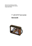
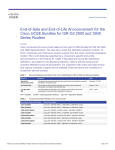
Thank you for purchasing this product. Please read the User’s Manual before using the product. User’s Manual is subject to change without notice. 3.5” LCD CCTV Test Monitor Accessories: Legend: 1. Carrying Case 2. Monitor Guard 3. Terminal Blocks 4. Battery Pack 5. AC Adapter 6. Meter Probes 7. Video Cable 8. Necklace 9. Belt 10. Hand Link SAFETY PRECAUTIONS Please read before using: The lightning flash with arrowhead symbol, within an equilateral triangle, is intended to alert the user to the presence of insulated dangerous voltage within the product’s enclosure that may be sufficient magnitude to constitute risk of electrical shock to persons. The exclamation point within an equilateral triangle is intended to alert the user to the presence of important operation and maintenance (servicing) instructions in the literature accompanying the appliance. 1. 2. 3. 4. 5. 6. 7. 8. Ground loop may cause electrode to short-circuit. User should follow the instructions below in order to avoid accidental shock: a. Don’t connect other inputs or outputs to device while in AC/DC mode. b. Don’t measure AC/DC voltage while in any other type of function. c. Don’t operate AC/DC function while in charging mode. Please read all details contained in the service manual before using this device. Do not attempt to disassemble the chassis, as this could lead to electric shock, or damage to the internal components of the device. Do not attempt to service this unit yourself unless you are authorized to do so. Opening cover could lead to exposure to dangerous voltage or other hazards. Refer all servicing of this device to qualified personnel only. Please connect all external components firmly before using to prevent damage. Please connect in accordance with the instructions, to prevent the device from accidental damage. Please don't use any organic solution or corrosive chemical to clean the chassis. While cleaning, please turn off the power to the device. Use a clean, lint-free cloth with a small amount of water to clean all surfaces. Please don't use this device under the following environmental conditions: Temperature lower than -10°C (14°F), or higher than +50°C (122°F). Exploring Your Test Monitor System indicator Green Light : Power On Red Light : Charging Directional Buttons MENU key MODE key POWER key ISP interface Power Switch DC Jack Cable test 10 PTZ Protocol Test ○ 11 RS-232 Port ○ 12 Video Extension ○ Up / Down / Left / Right to Navigate OSD Menu Menu to Adjust Device Parameters Switch Function Mode Turn On / Off Test Monitor Upgrade Firmware Interface Turn On / Off Test Monitor 9V Adapter Cable Open / Short Circuit Test (x 2 sets) PTZ Protocol Test for RS485 +/- Port Terminal Debug (for engineer only) Connect to Video In/Out and Audio In Cable Cord 13 Positive Probe ○ 14 Negative Probe ○ + Probe for DC / AC Voltage Measurement - Probe for DC / AC Voltage Measurement Functions & Operation Type A - Measurement 1. Video Level a. Power On device and push “MODE” key to go to the “VIDEO” page. b. Connect “Video Out” of device with “Video In” (yellow BNC connector) on video extension cord to measure the video level. c. System will auto-detect NTSC/ PAL video signal and the measured voltage value will be shown as below: 2. AC/DC Voltage a. Switch “MODE” key to “AC150V~250V”, “AC20V~150V” or “DC” page. b. Connect two ends of termination with probe to measure voltage. Caution: While in DC measurement mode, it is important to distinguish between the positive and negative (+/-) leads. c. The measured voltage will be indicated on screen as shown below: Type B - Tester 3. PTZ Control Test a. Switch “MODE” key to get “RS485” page, as shown below. b. Push the “MENU” key to enter the Protocol Setup. c. Make sure that the remote PTZ device protocol is set correctly, then configure the tester using the same protocol. Example - Protocol: PELCO P, Unit ID: 01, Baud Rate: 9600 d. Control the direction of the PTZ camera using the Directional Buttons. Press “Up + Right” key for Zoom In; “Down + Left” key for Zoom Out. View on monitor indicates that RS-485 communication is working. 3.1.PTZ control test:Call PTZ menu and call preset Before you can start to programme the speed dome, you need to switch to the PTZ-Mode of the monitor. Enter the speed dome menu: To enter the menu of the speed dome, please press the button ▲ and MENU button into PTZ menu with a “CAM” message. Press again or MODE button to release. Use the ▲▼ buttons to navigate through the menu. Push the menu button to open the sub item. Use the ◄► buttons to change the settings. Follow the operation instructions of the speed dome for further changes. Save and call presets: Push the ▼and MENU button to open the preset menu, use the MODE button to navigate through the sub items. Save preset: Set the desired position with the arrow keys and then switch to the menu item “save preset”. Press first the MENU button, now you can choose the desired preset number. With the ▲ and ▼ buttons you can change the preset number gradually. With the ◄ and ► buttons you can change the preset number in tenner steps. Push the menu button to save the preset. Call preset: To call an already saved preset position change to the sub item „call preset“. Choose the required preset number and confirm it with the MENU button. You have also the possibility to start a tour that is already programmed in the speed dome. Please refer to the predefined preset of the speed dome. Follow the operation instructions of the speed dome for further information. PTZ Speed: With this menu item you can adjust the speed of the navigation. With the ▲ and ▼ buttons you can change the preset number gradually. With the ◄ and ► buttons you can change the preset number in tenner steps. 4. Cable Test: (Open or Short Circuit test for 2 sets of wires.) a. Switch “MODE” key to get “CABLE TEST” page. b. Connect two ends of termination with “Cable Test Terminal” to test whether circuit status is OK(Short) or NG(Open) as shown below. c. The 2 test channels are independent, to allow testing of both parts of a 2-conductor cable simultaneously. 5. Audio Test: a. Switch “MODE” key to get “VIDEO” page. b. Click “Up” key or “Down” key to open or close speaker for testing the audio output. Default is ON as shown in the diagram below: Type C - Video Pattern Generator 6. Standard Pattern Output (for monitor testing) a. Switch “MODE” key to get “PATTERN OUT” page. b. Connect the “Video In” of monitor with “Video Out” of video extension cord to display 8-color bar standard pattern, as shown below. c. Switch between NTSC / PAL video formats using the “Down” key. OSD Menu Illustration 1. Language: Press the “Menu” key ”Down” key Language. Choose from English, Français, Deutsch, Italiano, ,Español, and Chinese languages. “Sleep Time” is a sleep mode timer setting; when the test monitor is not being used, the system will turn off power automatically after a period of time. 2. LCD Panel Color Adjust: Click “Menu” key to adjust the OSD menu as shown below: 3. Battery status: Displayed on the upper-right corner of the screen, showing battery capacity. When the level is full, the battery will provide 6 hours of usage, while the lowest level should provide about 5 minutes to check important data and prepare to power off. 4. Charging method: System indicator will show charging status. Charging the battery while powered off is better for the battery life and allows for faster battery charging time. 5. Calibration method: Adjust the Brightness value to 30, then press and hold the “Mode” key, and then the “Right” key to enter calibration mode. The default value is 128 and the user may adjust between values from 0~250 to decrease or increase the ratio from 0~2 times the measured value. The adjustable measurement parameters include Video level, AC and DC voltage, and the calibration values will be saved and retained until the next time a value is re-calibrated. NOTE: Before using the test monitor for the first time, please charge the battery for at least 5 hours to make sure that the battery is fully charged. This will extend the usage life of the battery. After the initial charge, the battery should only require charging for about 2~3 hours in order to be charged fully. This should provide enough power to use the device for about 5~6 hours. Battery life should allow recharging about 250 times, depending on the environment and amount of operation. Please follow the correct charging method in order to extend the life of the battery. CAUTION: 1. Although the test monitor can work and charge at the same time, you must not measure the AC voltage while battery is in charging mode! 2. When users see the flash of the F on the screen, this indicates that the fuse needs to be changed. For details on how to change the fuse, please check the user manual. When users see the flash of the F on the screen, the rest of the device functions should still work normally. 3. When the battery is totally discharged, please switch power to OFF while charging; do not attempt to operate and charge simultaneously when the battery has been totally discharged. Product Dimensions Specifications Model Name 3.5” LCD CCTV Test Monitor Display Size 3.5” Panel Backlight LED type Display Resolution 320 x 240 Charge Voltage 4.2V (+/- 10%) Battery 2200mA, Lithium Polymer Battery Charge Time 2~3 hours Standby Time Video Level Measurement 5~6 hours 0~2Vpp (Voltage peak-to-peak value) NTSC / PAL auto detection Pattern out 8-Color bars with 1V standard Vpp PTZ Protocol PELCO P or D Protocol Baud Rate 2400 / 4800 / 9600 bps AC Voltage Range 20~250 V DC Voltage Range 0~45 V Audio Test Built-in Speaker for Testing (8Ω/1W) Cable Test Open or Short Circuit Test (x 2 sets) Firmware Upgrade On-site Upgrade by ISP interface Weight NW/GW: 0.29kg / 1.07kg Dimensions 156 x 90 x 38 mm (with screen guard cover) Operating Temperature 0 to 45° Celsius (32 to 113°F) Storage Temperature -20 to 45° Celsius (-4 to 113°F) V1.5 85-TM0350-A002G-D