1
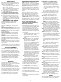
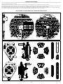
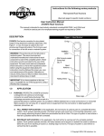
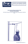
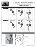
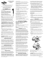
A CAPITAL SAFETY COMPANY Trusted Quality Fall Protection 3833 SALA Way, Red Wing, MN 55066-5005 800-328-6146 www.protecta.com 260 Export Blvd. Mississauga, Ontario L5S1Y9 800-387-7484 www.protecta.com INSTRUCTIONS FOR USE Protecta® Self Retracting Lifelines This instruction must be provided to the user of this equipment. YOU MUST READ AND UNDERSTAND, OR HAVE THE FOLLOWING INSTRUCTIONS EXPLAINED TO YOU BEFORE USING THIS EQUIPMENT. FAILURE TO DO SO COULD RESULT IN INJURY OR DEATH. This manual is intended to meet the Manufacturer’s Instructions as required by ANSI Z359.1-2007 and should be used as part of an employee training program as required by OSHA. WARNING All of the equipment which is recommended by Protecta should be used as part of a complete Protecta Fall Prevention System. The buyer or the user choosing to disregard this warning is solely responsible for the safety of the entire system. OSHA regulations require that the employer and the employee recognize that all components of the Personal Fall Arrest System (PFAS) be compatible with one another before use. No fall prevention system can guarantee that absolutely no injuries will be sustained should a sudden fall occur. Improper use of this equipment will increase the risk of serious injury. To obtain the optimum level of safety which Protecta’s fall prevention systems can provide, you must read or receive, understand and adhere carefully to all instructions given by Protecta. Applications: These mechanical devices are known as Fall Arrest Devices or Self Retracting Lifelines (SRL). A fall arrest device has two main functions: • To safely extend the working area where a harness with a 6 ft. (1.8 m) lanyard is inadequate. • To reduce the shock loading on the body by limiting the distance of the fall. The fall arrest devices can be mobile with a device travelling on a steel lifeline, fixed rail, or rope; or stationary with an extendable anchorage line which extends as the user moves away from the anchorage point and retracts as he moves towards the anchorage point. All Protecta SRLs are automatic and allow hand and body freedom of movement. IMPORTANT: If you have any questions on the use, care, or suitability of this equipment for your application, contact Protecta before proceeding. CENTRIFUGAL FORCE By using centrifugal force Protecta devices ensure that should a fall occur the brake is instantly engaged. Normal movement will not activate the braking mechanism and normal movement is not hindered as the lifeline extends and retracts freely. Should the lifeline receive a sudden pull caused by the event of a fall, the lifeline locks automatically. Protecta devices avoid violent arrests associated with full body safety harnesses. The mechanism will stop the user before excessive momentum is attained in a normal fall. PURCHASE SELECTION It is important that the selection of a device is made after the purchaser and supplier have both fully understood the application of the equipment. If the end use will be in abnormal atmospheres, or involves contact with acids, alkalis, sewer gas or anhydrous ammonia, additional information will be required before a choice of proper equipment can be made and purchased. USER TRAINING Instructions on handling are supplied with all safety equipment. It is the purchaser’s responsibility to ensure that his workers understand these instructions, have been trained in the correct use of all equipment and have been made aware of the importance of connecting to suitable structural anchorages. PROTECTA FALL PROTECTION DEVICES For almost fifty years Protecta Fall Protection Devices have been used in virtually every conceivable situation Form. No. 5902290 Rev. K for fall prevention. A collective fall prevention system should be used whenever possible. The Fall Arrestor may be preferred for work of short duration or due to the technical impossibilities of installing it in a collective fall prevention system. Reasons for using Protecta Fall Protection Devices are: 1. Freedom of movement is allowable within a much greater area. 2. The locking action of the Fall Arrest Device is almost instantaneous in the event of a fall. 3. The arrest load imposed on the body is below 1350 lbs. (6 KN). 4. The maximum free-fall distance does not exceed 2 ft. (0.6 M). 5. The retractable lifeline greatly reduces the possibility of entanglement on surrounding structures or physical hinderance by its constant yet light tension. SPECIAL FEATURES (depending on model) • Metal casing or exclusive shockproof material compound casing. • Full corrosion-resistant components. • Fully automatic; requires NO adjustment by user. • Self-retracting lifeline. • Less than 2 ft. maximum free fall distance. • 3/16 in. galvanized/stainless steel, 1 in. nylon web, Pro-Teq™ rope available on request. • 310 lbs.(141kg)/420 lbs (191 kg) maximum safe working load. APPLICABLE STANDARDS Meets rigorous standards such as : OSHA 1926 • ANSI Z359.1 • ANSI Z359.14 • B.S.I.5062 • D.I.N.23326 • A.F.N.O.R S 71-020 • C.S.A. Z 259-2.2 and 2.3 CAUTIONS •To be used only with an approved Full Body Harness. •Hold on to lifeline during rewinding. •Do not leave lifeline extended for long periods of time. WARNING: Never use a waist or chest belt of any type for fall arrest hazards. OPERATION AND USE WARNING: Read and understand all instructions and warnings on the labels attached to the device before using. These instructions and warnings are placed on the device for your protection. Be sure that you understand and follow these directions carefully. Before using this equipment make a visual inspection to ensure the serviceable condition of the device. Use the Inspection Checklist for guidance (located towards the rear of this manual). Under no circumstances should the SRL be used if the lifeline has any defect, i.e. broken or flattened wire strands, cut fibers, or is not retracting correctly. A. Check by pulling entire length of lifeline out and allowing its slow retraction through your protected hand (when making this check, always wear gloves to avoid the possibility of laceration by broken wire strands). for certification requirements. When more than one personal fall arrest system is attached to the same structure, the strength requirements stated above must be multiplied by the number of personal fall arrest systems attached to the structure. • From OSHA 1910.66 and 1926.500: Anchorages used for attachment of a PFAS shall be independent of any anchorage being used to support or suspend platforms, and must support at least 5,000 lbs. (22.2kN) per user attached, or be designed, installed, and used as part of a complete PFAS which maintains a safety factor of at least two, and is supervised by a qualified person. While using, always ensure that there is constant tension on the lifeline. Slack in the lifeline could result in an increase in fall distance. Move normally, sudden jerky movements will activate the locking mechanism. In the event of a fall, the fall arrest device must not be used until it has been visually checked by a competent person. Checks include : 1. Pull out total length of lifeline to ensure it is not damaged. 2. Pull lifeline out fast enough to lock the system; repeat operation 3-5 times to ensure satisfactory operation. 3. If the device’s operation remains questionable in operation or performance, it must be removed from service and returned to Protecta for further review. INSPECTION WARNING: Before using, read and understand all instructions contained in the user manual as well as warnings and instructions on all labels attached to the device. PRIOR TO EACH SINGLE USE, CHECK : 1. The connector at top of device and ensure freedom of movement. Check for signs of distortion, cracks, burns, or worn parts and ensure that keeper is closed. 2. The nut and bolt retaining connecting hook for signs of distortion, cracks, burns, and wear. 3. The main housing for signs of distortion or cracks. 4. That main body housings fit evenly and that there are no gaps between sections. 5. That all screws and rivets are present and tightened. 6. The device for spring action; the entire length of the lifeline should retract fully after extension. 7. The locking action of the device-jerk on the end of the lifeline; lifeline should retract easily into the device. 8. Snap hooks for signs of distortion, cracks, burns, and wear. 9. The coil pin securing the top swivel is fully inserted in the SRL housing and the fastening screw is secure. YES Fastening Screw B. Test the locking mechanism several times by jerking down on the lifeline. Any device with suspected faults should be immediately withdrawn from service and returned to Protecta for further examination and replacement if necessary. After connecting the Fall Arrest Device to a safe anchorage point attach the snap hook at the end of the lifeline to the dorsal D-ring of the harness, ensuring that the snap hook closes fully. Medical evidence indicates that it is preferable to be suspended from the dorsal D-ring. NO In situations where it is necessary to use a front D-ring as a point of attachment such as working on a fixed ladder a harness with chest D-rings must be used. Refer to OSHA requirements Protecta highly recommends the exclusive use of Protecta full body harnesses with all its individual fall prevention systems. Make every effort to keep the lifeline clean and free from dry mud, cement, etc. Failure to do so can result in premature locking and rewind failure of the device. Never allow the lifeline to contact sharp abrasive edges, i.e. girders, roofing panels, etc. which could damage and ultimately weaken the lifeline. ANCHORAGE STRUCTURE The anchorage to which the SRL is attached must be capable of sustaining static loads in the directions applied by the personal fall arrest system of at least 3,600 lbs. with certification of a qualified person, or 5,000 lbs. without certification. See ANSI Z359.1 10. That all labels are present and fully legible. 11. The entire device for corrosion. 12. The condition of lifeline. 13. The impact load indicator, if so equipped (webbing or mechanical). CAUTION: Device should be stored with lifeline retracted during periods of non-use. If after inspection there is any doubt as to the safety or appearance of the device, it should be removed from service and returned to PROTECTA for further inspection. ©Protecta 2013 DEVICE CHECKUP Before beginning this procedure ensure that you are wearing gloves as broken wires along the lifeline can cause severe cuts and lacerations. 1. Begin the inspection procedure at the ferrule, check that it is correctly fitted and there are no signs of distortion, cracks, or corrosion. 2. Check mechanical swages for signs of cracks, distortion, or corrosion-ensure that they are fitted correctly and are not cutting into the lifeline. 3. During the inspection of the lifeline the following procedure should be used: • Pass the lifeline slowly through your hands • Flex the lifeline every few inches to allow for complete inspection of broken wires. 4. Check the entire length of lifeline for signs of deterioration or damage. Should there be signs of deterioration or damage in the lifeline or signs that the lifeline is not in safe working condition the Fall Arrest Device must be returned to Protecta for lifeline replacement. INSPECTION OF STEEL LIFELINES The following explains the principal causes of deterioration of galvanized steel lifelines and indicates the signs by which the deterioration can be recognized. Mechanical damage/crushing: Crushing the lifeline often results in a flattened or bent section of the lifeline. Mechanical damage/cutting: Movement over sharp edges or projections while the lifeline is under tension can result in damaged strands and broken wires. Abrasion: Abrasion to the lifeline results in localized wear. The outer wire strands appear flattened and are brighter in appearance. Strand Core Protrusion: Core protrusion usually results from the lifeline having been subject to a shock load. Kinking: Kinking occurs by the deformation of the lifeline during handling when a loop is formed and then tightened without allowing for rotation about its axis. Typical examples of localized wear and deformation are created at a previously kinked portion of the lifeline. Corrosion: The presence of corrosion on the exterior surface of the lifeline is recognizable by its roughness and pitting. Wire breaks will generate from these cracks or pitting. Electric Arcing/Heat damage: Heat damage is noticeable by a blue coloring on the wire surface or by fusion of the wire surface and the presence of welding signs. INSPECTION OF WEBBING The webbing material must be free of frayed, cut, or broken fibers. Check for tears, abrasions, mold, burns, or discoloration, etc. The webbing must be free of knots, excessive soiling, heavy paint buildup, and rust staining. Check for chemical or heat damage indicated by brown, discolored, or brittle areas. Check for ultraviolet damage indicated by discoloration and the presence of splinters or slivers on the webbing surface. All of the above factors are known to reduce webbing strength. Damaged or questionable webbing should be replaced. Inspect stitching for pulled or cut stitches. Broken stitches may be an indication the energy absorbing lanyard or energy absorber component has been impact loaded and must be removed from service. SERVICING Protecta Fall Arrest Devices, like all mechanical mechanisms, require periodic servicing to ensure safe and proper working condition. ANSI Z359.1 requires formal inspection of the SRL annually by a competent person other than the user. Formal inspection should determine the need for and frequency of servicing. In the event of a Fall Arrest Device being subject to shock loading, as the result of a fall or any other sudden shock, it must be removed from service, examined, repaired, and reset by Protecta before it is placed back into service. Under no circumstances shall the user carry out repairs or modifications. All repairs must be carried out by Protecta or an authorized service center. Do not disassemble the SRL. INSPECTION OF METAL COMPONENTS D-Rings (on Full Body Harnesses )-check for distortion, sharp edges, burrs, cracks, or worn parts. For plated components, check for deterioration in the protection and for signs of corrosion. Snap Hooks Check snap action, ensure that the return spring is functioning properly and that there is not sideways play on the latch in the closed position. Check the hooks for distortion, sharp edges, burrs, cracks, and worn parts. For plated components check for deterioration in the protection and for signs of corrosion. Automatic Locking Hooks (Carabiners) Check that the trigger opens fully and that it returns automatically revolving the ferrule into the locked position. Check for distortion, sharp edges, burrs, cracks, or worn parts. For plated components check for deterioration in the protection and for signs of corrosion. Screwgate Hooks Check snap action and ensure that ferrule functions satisfactorily. Check for distortion, sharp edges, burrs, cracks, and worn parts. For plated components check for deterioration in the protection and for signs of corrosion. ANY FALL ARREST COMPONENT WITH SUSPECTED FAULTS MUST BE IMMEDIATELY WITHDRAWN FROM SERVICE AND RETURNED TO PROTECTA FOR INSPECTION. WARNINGS 1. Install the Fall Arrest Device above head height. Avoid working at more than 30° from the vertical. A fall from more than 30°. from vertical will produce a swing effect which could cause injury or death as a result of striking an obstruction. If the SRL is not mounted overhead (for example, an SRL mounted between dorsal D-ring and foot level, such as in an aerial lift) the following guidelines must be followed: A. The aerial work platform must have a guardrail system and a closable gate around its perimeter unless the anchorage level for the SRL is overhead. A suitably designed anchorage must be available for each SRL as part of the platform. B. Swing fall hazards may exist, especially when working near corners, or out away from the SRL. Added fall clearance may be required, depending on the swing fall hazard. C. For situations where the SRL is mounted below shoulder height, SRL models that incorporate an external energy absorber are highly recommended to reduce the risk of damaging the lifeline should a fall occur over the guardrail. SRL models that do not incorporate an external energy absorber can be used if a separate in-line energy absorber is installed between the end of the lifeline and the harness. This energy absorber is connected in-line between the harness dorsal d-ring and the SRL’s snap hook. Capital Safety offers a special model energy absorber (part number 1220362) for this purpose that includes a snaphook on one end and a D-ring on the other to ensure compatible connections can be made. Do not use energy absorbing lanyards for this purpose. D. Sharp edges which the lifeline may contact during a fall could cut or damage the SRL’s lifeline. Sharp edges must be avoided or covered over. Falls where the lifeline may slide along a sharp edge must be guarded against. E. Employee training should be conducted to help assure a safe working environment. 2. The Fall Arrest Device permits complete freedom of movement, however, ensure that you move normally as sudden or quick movements will activate the locking mechanism. 3. IT IS NOT PERMISSIBLE to make additions or alterations to this equipment. 4. Anchorage point should allow end user to move without interfering with other workers. Never allow your lifeline to cross the lifeline of another worker. 5. NEVER ALLOW more than one person at a time to be connected to the fall arrest device. 6. Follow manufacturer’s instructions for the correct use of the fall arrest device and associated accessories. 7. Before choosing an anchorage point survey the surrounding area for hazards that could interfere with your safety: 2 DO NOT INSTALL FALL ARREST DEVICES: A. Where the possibility exists of the lifeline contacting power lines, live lifelines ,etc. B. Where obstructions may cause the lifeline to become entangled. In the event of a fall, the brake may not engage, or the lifeline runs the risk of passing over a sharp edge; i.e., girders, etc., which could shear the lifeline causing injury or death. 8. Do not use personal fall arrest devices where, during an unexpected fall, the body could strike obstructions that will cause injuries or be fatal to the user. 9. Do not use personal fall arrest devices where obstructions may slow down the user and prevent the mechanism of the device from locking. 10. Protecta SRLs are not adequate for use in protecting workers in grain silos, coal bunkers, slack hoppers, or other areas where there is a danger of suffocation by immersion in the material over which the worker is standing should a collapse happen slowly and not cause the locking mechanism to activate. ALWAYS ensure that there is approximately 6 feet (1.8 M) of free fall space beneath the working position. 11. Do not leave Protecta SRLs installed for long periods of time in an environment where corrosion of the main components could occur as a result of vapors rising from organic materials. Sewage and fertilizer plants, for example, should be avoided due to the high concentrations of ammonia present. 12. Do not use Protecta SRLs where there is a potential risk of incendiary sparking due to contact friction between the SRL, its lifeline, or the device’s metal parts and rusted steel or iron in the work area. 13. NEVER attach clips, etc., as a positioning device to the lifeline which will prevent the lifeline from retracting automatically. This practice is dangerous as it leaves excessive slack in the lifeline which, in the event of a fall, will increase the fall distance and the shock load on the body to unacceptable levels. 14. Avoid allowing the lifeline to pass between your arms or legs while moving about or working. Avoid working where an object may fall and strike the lifeline resulting in loss of balance or damage to the lifeline. 15. Avoid allowing the lifeline to contact paints, concrete, bitumen, oils, etc. which will adversely affect the SRL if it enters the mechanism. 16. Always keep the steel lifeline clean and free of dry mud, cement, etc. Failure to do so could result in premature locking and rewinding failure. 17. When detaching from the SRL do not quickrelease the lifeline allowing uncontrolled rewind back into the device. This can be dangerous and there is a probability that the lifeline will rewind unevenly. Uneven rewind of lifeline can prevent full retraction. 18. Do not leave lifeline extended for long periods of time. 19. Always wear gloves while inspecting the lifeline to avoid the possibility of laceration by broken wire strands. 20. DO NOT repair equipment in the field. Only Protecta is equipped to make repairs of Protecta devices. 21. DO NOT combine self-rewinding personal fall arrest devices with other fall arrest systems (attach only to a 3,600 lb. anchor point and connect directly to the dorsal D-ring of a Protecta Full-Body Harness). 22. DO NOT OPEN the fall arrest device as the spring is under tension. 23. CHEMICAL HAZARDS: Solutions containing acid or caustic chemicals, particularly at elevated temperatures, may damage Protecta SRLs. When working with such chemicals, frequent inspection of the entire SRL must be completed. Chemical damage to the lifeline is difficult to detect and it is recommended that the lifeline be replaced periodically to ensure safety. The lifeline must be replaced by an authorized service agent. Consult Capital Safety if in doubt about using this equipment around chemical hazards. 24. Exercise caution when using this equipment around moving machinery or electrical hazards. RESCUE When using this equipment, the employer must have a rescue plan and the means at hand to implement it and communicate that plan to users, authorized persons, and rescuers. CLEANING AND STORAGE Wipe off all surface dirt, mud, dust, etc. with a damp sponge. To clean off grease or oil use a mild solution of water and household detergent. Complete by sponging with clear water and completely dry with a clean cloth. After cleaning the fall arrest device, it should be allowed to dry thoroughly in a hanging position free from excessive heat or steam exposure. Protecta fall arrest devices must be stored in a clean, cool, and dry area away from chemical fumes or corrosive elements. Never store in areas exposed to direct sunlight. It is preferred that fall arrest devices be kept, when not required for use, in properly designed storage units which allow for adequate ventilation. Do not subject a fall arrest device to unnecessary strain or pressure during storage. Do not expose the fall arrest device to excessive heat, cold, or humidity during storage. Do not allow the equipment to contact sharp edges, corrosives, or other likely causes of damage while the device is in storage. ONE OR MORE OF THESE LABELS WILL APPEAR ON YOUR PRODUCT ANSI CSA 3 TABLE 1 - SPECIFICATIONS MEDICAL WARNING For user safety, workers with physical disabilities or muscular problems should receive medical advice prior to using fall arrest equipment. UNDER NO CIRCUMSTANCES should pregnant women or minors use Capital Safety fall arrest systems. A worker’s ability to accommodate arrest forces inflicted on the body in the event of a fall are seriously affected by age and fitness of the user. Only those in good health should work at heights. Please contact your physician should there be reason to doubt your ability to absorb the shock load on your body in the event of a fall. WARRANTY WARRANTY TO END USER: D B Industries, Inc., dba CAPITAL SAFETY USA (“CAPITAL SAFETY”) warrants to the original end user (“End User”) that its products are free from defects in materials and workmanship under normal use and service. This warranty extends for the lifetime of the product from the date the product is purchased by the End User, in new and unused condition, from a CAPITAL SAFETY authorized distributor. CAPITAL SAFETY’S entire liability to End User and End User’s exclusive remedy under this warranty is limited to the repair or replacement in kind of any defective product within its lifetime (as CAPITAL SAFETY in its sole discretion determines and deems appropriate). No oral or written information or advice given by CAPITAL SAFETY, its distributors, directors, officers, agents or employees shall create any different or additional warranties or in any way increase the scope of this warranty. CAPITAL SAFETY will not accept liability for defects that are the result of product abuse, misuse, alteration or modification, or for defects that are due to a failure to install, maintain, or use the product in accordance with the manufacturer’s instructions. CAPITAL SAFETY’S WARRANTY APPLIES ONLY TO THE END USER. THIS WARRANTY IS THE ONLY WARRANTY APPLICABLE TO OUR PRODUCTS AND IS IN LIEU OF ALL OTHER WARRANTIES AND LIABILITIES, EXPRESSED OR IMPLIED. CAPITAL SAFETY EXPRESSLY EXCLUDES AND DISCLAIMS ANY IMPLIED WARRANTIES OF MERCHANTABILITY OR FITNESS FOR A PARTICULAR PURPOSE, AND SHALL NOT BE LIABLE FOR INCIDENTAL, PUNITIVE OR CONSEQUENTIAL DAMAGES OF ANY NATURE, INCLUDING WITHOUT LIMITATION, LOST PROFITS, REVENUES, OR PRODUCTIVITY, OR FOR BODILY INJURY OR DEATH OR LOSS OR DAMAGE TO PROPERTY, UNDER ANY THEORY OF LIABILITY, INCLUDING WITHOUT LIMITATION, CONTRACT, WARRANTY, STRICT LIABILITY, TORT (INCLUDING NEGLIGENCE) OR OTHER LEGAL OR EQUITABLE THEORY. Model Number 3101112 Lifeline Material and Size Lifeline Length POLYESTER WEB 130-310 lbs 900 lbs 42 in (2.4 m) (59-140 kg) (4 kN) (1.1 m) 10 ft 130-310 lbs 900 lbs 42 in (3.0 m) (59-140 kg) (4 kN) (1.1 m) 11 ft 130-310 lbs 900 lbs 42 in (3.3 m) (59-140 kg) (4 kN) (1.1 m) 20 ft 130-310 lbs 900 lbs 42 in (6.1 m) (59-140 kg) (4 kN) (1.1 m) 6 ft 130-420 lbs 1350 lbs 42 in (1.8 m) (59-191 kg) (6 kN) (1.1 m) 11 ft 130-310 lbs 900 lbs 42 in (3.3 m) (59-140 kg) (4 kN) (1.1 m) 15 ft 130-310 lbs 1350 lbs 42 in (4.5 m) (59-140 kg) (6 kN) (1.1 m) 30 ft 130-310 lbs 1350 lbs 42 in (9.1 m) (59-140 kg) (6 kN) (1.1 m) 50 ft 130-310 lbs 1350 lbs 42 in (15.2 m) (59-140 kg) (6 kN) (1.1 m) 66 ft 130-310 lbs 1350 lbs 42 in (20.1 m) (59-140 kg) (6 kN) (1.1 m) 100 ft 130-310 lbs 1350 lbs 42 in (30.5 m) (59-140 kg) (6 kN) (1.1 m) POLYESTER WEB 1 in (25 mm) x .055 in (1.4 mm) 3101101, 3101102, 3101104, 3101105, 3101106, 3101108, 3101109, AD111 (A, AR, ARA, B, BR, D, DR, E, ER, R) POLYESTER WEB 3101127, AD120 (A, AR, B, BR, D, DR, E, ER) POLYESTER WEB 3506060, 3506062 1 in (25 mm) x .055 in (1.4 mm) 1 in (25 mm) x .055 in (1.4 mm) 7x19 GALVANIZED STEEL CABLE 3/16 in (5 mm) dia. 3506026, 3506027, AD210B, AD211B 7x19 GALVANIZED STEEL CABLE 3506051, 3506055, AD115B 7x19 GALVANIZED STEEL CABLE AD212 (AG, AG1) 3/16 in (5 mm) dia. 3/16 in (5 mm) dia. 7x19 GALVANIZED STEEL CABLE 3/16 in (5 mm) dia. AD215AG, AD515AG 7x19 GALVANIZED STEEL CABLE 3/16 in (5 mm) dia. AD222AG 7x19 GALVANIZED STEEL CABLE 3/16 in (5 mm) dia. AD230AG 7x19 GALVANIZED STEEL CABLE 3/16 in (5 mm) dia. Maximum Arrest Distance 8 ft 1 in (25 mm) x .055 in (1.4 mm) AD110FC Capacity Maximum Arresting Force INSPECTION LOG Inspection Date Item Inspected APPROVAL: APPROVAL: APPROVAL: APPROVAL: APPROVAL: APPROVAL: APPROVAL: APPROVAL: APPROVAL: APPROVAL: APPROVAL: APPROVAL: APPROVAL: APPROVAL: APPROVAL: APPROVAL: APPROVAL: 4 Action Taken Maintenance Performed