1
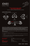
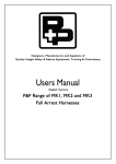
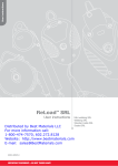
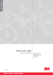
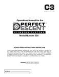
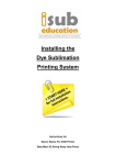
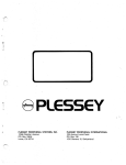
Satra Technology Centre
Kettering, Northamptonshire
NN16 8SD United Kingdom
OPERATOR’S MANUAL
Doc No: MT01 Revision 4
Effective: 10TH OCTOBER 2012
M_TLineOperatorsManual_Final_160812.indd 1
16/10/2012 19:22
DESCRIPTION OF EQUIPMENT
INTRODUCTION
This Manual contains safety information and instructions for operating the T-Line system.
This Manual should be stored in an area where it is accessible to operators of the T-Line system.
Continued improvement and advancement of product design may have caused changes to your T-Line
system, which are not included in this Manual.
Some photographs or illustrations in this Manual may show details or attachments that are different
from your T-Line system. Whenever a question arises regarding your T-Line, or this Manual, please consult the Meridian Safety Pty Ltd website at www.meridiansafety.com for the latest available information.
Further information on operating the T-Line system is available in training material and courses. Further
enquiry regarding these materials and courses should be directed to: [email protected]
The Equipment Record and an Operators Manual must be supplied to the end user when the T-Line is
sold, resold or otherwise made available for use. This is to ensure that the end user gets the necessary
information for the safe use of the T-Line system.
The T-Line is a twin lifeline system.
The T-Line is a device containing twin lifelines on separate reels that rotate on a common shaft. The
lifelines automatically pay out and retract during normal movement of the operator – and automatically
lock at the onset of a fall.
CUSTOMER SERVICE
Please contact the authorized T-Line distributor in your area for enquiries regarding the operation,
Periodic Examination and Recertification and Repair of your T-Line system. The distributor nearest you
can be found by consulting www.meridiansafety.com
IMPORTANT SAFETY INFORMATION
• Do not use the T-Line unless you have read and understand the instructions and warnings in this Manual.
Failure to follow the instructions or heed the warnings or improper operation could result in injury or death.
• Do not tamper with or make any alterations to the T-Line.
• The T-Line shall not be used outside its limitations as described in this Manual, or for any purpose
other than that for which it is intended.
• The operation and maintenance of the T-Line system must comply with the work safety laws of the
jurisdiction in which it is used. Compliance may include the requirement for a Risk Assessment or
Fall Hazard Survey Report.
• Operators of the T-Line system must be properly trained and competent.
• A full body harness suitable for fall-arrest is the only acceptable body holding device that can be
used with the T-Line system.
• Operators must carry out a Pre-Use Check of the equipment, as per the instructions in this Manual,
to ensure that it is in a serviceable condition and operates correctly before it is used.
• It is essential for safety that equipment is withdrawn from use immediately if the red indicator tab on
the connector is exposed or should any doubt arise about its condition for safe use.
• Do not remove the labels from the T-Line. Replace labels that are illegible.
• For protection of one person only.
• Operators should be fit and healthy – otherwise consult a physician before using the T-Line. Do not
use if pregnant.
• A rescue plan shall be in place to deal with any emergencies that could arise during the work
M_TLineOperatorsManual_Final_160812.indd 2-3
The T-Line is designed to provide
a safe means of accessing and
working at height.
• The operator can move freely along
horizontal walkways or platforms.
When the user is moving horizontally, one
lifeline pays out whilst the other retracts
- and the T-Line will not lock.
• If the user falls, the T-Line will arrest the
fall and hold the user. If the user falls, both
lifelines pay out quickly - and the T-Line
locks. The pulley brake grips the locked
lifeline and prevents sliding.
• The user can safely climb and descend.
When climbing, both lifelines retract – and
the T-Line will not lock. When descending
under normal conditions, both lifelines pay
out slowly – and the T-Line will not lock.
• The T-Line has an integrated rescue
function. The hand operated winch can be
used to bring the suspended person back
to the T-Line Unit.
T-Line Anchor Eye
Pulley Anchor Eye
Main Lifeline
Pulley Lifeline
Pulley Lifeline Connector
Connector Ring
Pulley
Pulley Stowage Pocket
Main Lifeline Connector - swivel
connector with fall indicator
Rescue Handle
Ancillary Anchor Eye
for Stabiliser Sling
Serial Number (opposite face)
IMPORTANT:
The Pulley Lifeline Connector (5) must be properly
secured to the Connector Ring (6) when using the
T-Line in twin line mode. When using the T-Line in
single line mode, the Pulley Lifeline Connector (5) must
either be connected to the Ancillary Anchor Eye (11) or
a certified fall arrest anchor point rated to at least 15kN
(3400 lbs). Failure to do so could result in serious injury
or death. Always ensure that an alternate means of fall
protection is utilized whilst changing between modes.
16/10/2012 19:22
INSTALLATION
1
MAKING PROPER CONNECTIONS
2
The T-Line must be attached with a suitable
anchor system to a structure with a minimum
strength of 22kN / 5,000lb
The pulley must be attached with a suitable anchor
system to a structure with a minimum strength of
22kN / 5,000lb
The Pulley is taken from the Pulley Stowage Pocket
and moved to the far end of the elevated work area
– extracting the Pulley Lifeline along the way.
The Pulley Lifeline loops around the Pulley before
being attached to the Connector Ring using the
Pulley Lifeline Connector.
The T-Line and Pulley must be installed overhead
The Pulley must not be mounted below the T-Line
Do not allow slack in anchor slings as this will
increase arrest distance.
Installation of a 24m T-Line unit must be carried
out by an Authorised T-Line Installer
Anchorage Minimum Strength
22kn / 5,000lb
SAFE WORKING AT HEIGHTS DURING INSTALLATION
Ensure that the risk of fall from height is controlled during installation. For example, a mobile elevated
work platform may be used during installation.
1
The Pulley Lifeline must be attached
to the Connector Ring using the Pulley
Lifeline Connector.
2
The Main Lifeline is terminated with
a swivel connector – carabineer or
snaphook – with fall indicator.
3
The operator attaches to the
Main Lifeline to the dorsal
attachment point of their full
body, fall arrest harness.
ANCHOR POINT SPECIFCIATION AND CONNECTION
The anchorage and structure to which the T-Line is attached shall be capable of sustaining a static load
of 22.2kN / 5,000lb. Assess the building or structure and verify the adequacy of the anchor point before the system is put in
to service.
A suitable connector and anchor system must be used to connect the T-Line to the supporting structure. For
example: the T-Line Clevis Anchor Point, the T-Line Beam Clamp or the T-Line Anchor Sling (each sold separately). Do not allow slack in anchor slings as this will increase arrest distance.
All components and subsystems should also comply with applicable Standards.
Follow manufacturer’s instructions. Unless specifically allowed by the manufacturer, slings should not
be choked and lanyards should not be back-hooked. Connectors should be compatible in size and
shape to prevent rollout.
M_TLineOperatorsManual_Final_160812.indd 4-5
16/10/2012 19:22
GENERAL
PRE-USE CHECK
Do not pass the lifeline(s) over sharp or abrasive edges.
Do not allow lifelines to come into contact with live electrical sources
Do not allow the lifeline(s) to deflect around plant and equipment or other obstacles.
Do not allow chemical reagents to contact the lifelines, casing or internal mechanism
Do not cross over with other lifelines.
Do not allow the lifeline(s) to pass under head, arms or legs or wrap around the body.
Do not hold or lock off the lifeline(s).
Do not let the lifeline(s) retract uncontrolled.
Do not allow foreign material to enter casing.
Avoid using the T-Line in hazardous environments such as extremes of temperature or highly corrosive
atmospheres.
Pre-Use Checks are essential and should be carried out by the operator each time, before the T-Line
system is used.
SAFE ACCESS AND CONTINUOUS PROTECTION
Ensure that users can approach and connect to the T-Line without being exposed to a risk of fall. For
example: the Main Lifeline Connector or a tag to the Main Lifeline Connector should be left in a suitable
location so that users may connect to the system before moving to where there is a risk of fall. The
same applies to egress and disconnecting.
If the Pre Use Check finds any defect or should any doubt arise about its condition for safe use it is
essential for safety that equipment is not used and withdrawn from use immediately.
Check the Equipment Record to ensure that that the Periodic Examination and Recertification is up to date.
The Pre-Use Check of the T-Line consists of visual checks and checks of operation.
• Visually inspect the T-Line casing and lifelines for signs of damage or cracking that may reduce the
structural integrity of the device in any way.
• Withdraw approximately 1m of each lifeline and check that it remains under tension and then
rewinds smoothly
• Withdraw the Main Lifeline rapidly to check that it locks
• Inspect the swivel connector with fall indicator. If any portion of the indicator reveals the red marker,
the T-Line should be removed from service.
Check the fall-arrest harness, other connectors and anchor slings (if used) as per the manufacturer’s
instructions.
Ensure continuous connection to the T-Line whenever there is a risk of fall from height; or if not connected
and there is a risk of fall from height, then an alternate means of fall protection must be employed.
TRANSPORT
RESCUE
Ensure that the T-Line is fully retracted with the Pulley stowed in the Pulley Stowage Pocket in
preparation for transport. Ensure that the T-Line is protected from excessive vibration or impact
during transport.
1
2
PERIODIC EXAMINATION
AND RECERTIFICATION
The continued efficiency and durability of the T-Line system and the safety of the user depends on
regular Periodic Examination and Recertification.
Periodic Examination and Recertification is additional to the Pre Use Check and is a more formal, indepth inspection and must be carried out at intervals of 12 months or less.
Under extremely severe corrosive liquid or abrasive dust exposures or for operation under extremes of
temperature, more frequent Periodic Examination and Recertification may be necessary. Release the Rescue Handle by removing the
retaining pin.
Fold the handle down and align the slot in the handle
with the shaft in the centre of the winch boss.
Ensure that the handle is pushed fully into the
winch boss. Once engaged, the handle will be
retained by the sprung loaded steel ball.
M_TLineOperatorsManual_Final_160812.indd 6-7
Rotate the Rescue Handle in the clockwise
direction to transport the suspended user towards
the T-Line unit.
Maintain constant visual contact with the user. Do
not harm the rescue subject. Stop winching if the
rescue subject is caught or snagged.
Periodic Examination and Recertification is only to be conducted by an Authorized Service Agent.
WITHDRAWAL FROM USE AND REPAIR
It is essential for safety that equipment is withdrawn from use immediately should any doubt arise about
its condition for safe use.
Repairs are only to be conducted by an Authorized Repair Agent.
16/10/2012 19:22
EQUIPMENT RECORD
LABELS
Documentation is a key element of a well-managed personal protective equipment program.
Equipment Records should be maintained as proof of Periodic Examination and Recertification and Repair.
It is the responsibility of the user organization to enter onto the Equipment Record the details required.
Shows the correct
orientation of the
T-Line once installed
Engraving a “1”, “2” or “3” in
this table shows the month
and year of last service and
type of service performed ie
Level 1, 2 or 3.
CLEANING AND STORAGE
Use a damp (not wet) cloth to remove dirt or other contaminants from the casing. Do not use abrasives
or solvents. Mild detergent may be used but residue must be wiped away.
Use a bristle brush to remove dirt or other contaminants from the lifelines. Do not use a wire brush. Do
not use gasoline or solvent. Lubrication may be applied to a clean dry lifeline with a cloth.
Never immerse in water. If water does get into the casing, hang the unit and slowly withdraw each
lifeline allowing the water to run out. Use a clean dry cloth to wipe the lifeline dry as it returns. Repeat
if required.
Maximum Span
that the T-Line
may be used upon
Store the T-Line in a clean, dry place.
EQUIPMENT RECORD
Serial Number:
Owner:
Date of Manufacture:
Name of Organisation:
Date of Purchase:
Address:
Remove Pin
Date first put into use:
Fold Handle Down
DateActivity
Remarks
Name & signature
of Competent Person
Next service due
POSES
ION PUR
ORD -
T REC
UIPMEN
EQ
M_TLineOperatorsManual_Final_160812.indd 8-9
STRAT
U
L
L
I
R
FO
ONLY
Rotate Handle in
clockwise direction
Image showing
how to make
proper connections
16/10/2012 19:22
12m /40’
SAFE LIMIT OF OPERATION
T-LINE SAFETY SYSTEM MODEL T01
FREE FALL
The operator must remain below the T-Line and the Pulley. When the operator is within the vertical Safe Limit of Operation, the Lifelines will exhibit retraction
tension and the connector ring will be above the operator’s head. Never work at a level where the
operators head is above the connector ring. (Note: It is normal for the Lifelines to exhibit some catenary
or sag, particularly at wider spans.)
PENDULAR SWINGS
The operator must remain between the T-Line and the Pulley. Minimize pendular swings by working directly below the Pulley Lifeline which runs between the T-Line
and the pulley.
FALL CLEARANCE
It is essential that there is adequate clearance under the system so that in the event of a fall the
operator will not strike the ground or any obstacle.
SPECIFICATION MODEL T01
The 12m / 40’ T-Line can be installed at a
maximum span of 12m / 40’. At this span, the
maximum vertical reach is 6m / 20’.
HEIGHT
The T-Line can be installed for a maximum
vertical reach of 12m / 40’. At this vertical reach,
the maximum span is 6m / 20’.
The T-Line can be installed at spans and vertical
reach between the limits as set out above.
MAXIMUM SPAN
MAXIMUM VERTICAL RANGE
MAXIMUM FALL ARREST DISTANCE
MAXIMUM FALL ARREST FORCE
ANCHORAGE RATING REQUIREMENT
WIRE ROPE MIN BREAKING FORCE
(5mm diameter, 7x19 Strand) WEIGHT
12m /
@ 12m / 40’ span 6m /
@ 6m / 20’ span 12m /
1.8m /
6kN /
22kN /
17kN /
22.5kg /
40’
20’
40’
6’
1,350lb
5,000lb
3,820lb
50lb
HEIGHT / 2
If you have any questions about how to configure
and use your T-Line safely, then contact Meridian
Safety at [email protected]
M_TLineOperatorsManual_Final_160812.indd 10-11
SINGLE LINE MODE
16/10/2012 19:22
24m /80’
XL T-LINE SAFETY SYSTEM MODEL T01L
The 24m / 80’ T-Line can be installed at a
maximum span of 24m / 80’. At this span,
the maximum vertical reach is 20m / 65’.
For spans greater than 20m/65’ and up to
24m/80’, the 24m/80’ T-Line can provide
a vertical range of 20m/65’. For spans of
18m/60’ or less, this T-Line can provide a
vertical range equal to that of the span.
The T-Line can be installed at spans and
vertical reach between the limits as set
out on this page
SAFE LIMIT OF OPERATION
The installation of the 24m T-Line must be
carried out by an authorised T-Line Installer.
FREE FALL
The operator must remain below the T-Line and the Pulley. When the operator is within the vertical Safe Limit of Operation, the Lifelines will exhibit retraction
tension and the connector ring will be above the operator’s head. Never work at a level where the
operators head is above the connector ring. (Note: It is normal for the Lifelines to exhibit some catenary
or sag, particularly at wider spans.)
PENDULAR SWINGS
The operator must remain between the T-Line and the Pulley. Minimize pendular swings by working directly below the Pulley Lifeline which runs between
the T-Line and the pulley.
Produce a safe limit of operation description for both the 12m and 24m T-Line when being used in
V-Line configuration.
FALL CLEARANCE
HEIGHT
If you have any questions about how
to configure and use your T-Line safely,
then contact Meridian Safety at
[email protected]
It is essential that there is adequate clearance under the system so that in the event of a fall the
operator will not strike the ground or any obstacle.
HEIGHT
Produce a safe limit of operation diagram and description for single line mode.
HEIGHT / 2
*Spans of less than 14m may
require shortening of lifelines.
M_TLineOperatorsManual_Final_160812.indd 12-13
SINGLE LINE MODE
SPECIFICATION MODEL T01L
MAXIMUM SPAN
24m /
HEIGHT / 2
MAXIMUM VERTICAL RANGE
@ 24m / 80’ span 20m /
@ 18m / 60’ span 18m /
@ 12m / 40’ span 12m /
MAXIMUM FALL ARREST DISTANCE 1.8m /
MAXIMUM FALL ARREST FORCE
6kN /
ANCHORAGE RATING REQUIREMENT 22kN /
WIRE ROPE MIN BREAKING FORCE 17kN /
(5mm diameter, 7x19 Strand) WEIGHT
22.5kg /
80’
65’
60’
40’
6’
1,350lb
5,000lb
3,820lb
50lb
16/10/2012 19:22
WARRANTY
CORRECT / INCORRECT USE
SINGLE
LINE MODE
TWIN
LINE MODE
MAX 24M (80’)
MAX 24M (80’)
Meridian Safety Pty Ltd warrants to the owner-user that Meridian Safety’s
DETAIL VIEW
T-Line product will be free from defects in material and workmanship. This
warranty for new products is limited to two years from the date of purchase.
DETAIL VIEW
Meridian Safety Pty Ltd’s obligations under this warranty are limited to the
replacement of the equipment or repair of the equipment. Meridian Safety Pty Ltd
shall not be liable to the customer for any incidental, consequential, exemplary,
special or punitive damages, nor for any loss of revenue, profit or use arising out
of a breach of this warranty or in connection with the sale, maintenance, use,
operation or repair of the product. In no event will Meridian Safety Pty Ltd be
Sloping Roofs / Anchor Points at different Heights
liable for any amount greater than the purchase price of the defective product.
This warranty, during the original warranty period, extends beyond the original
purchaser to subsequent owners of the T-Line.
Repairs carried out under warranty do not extend the warranty period.
The warranty provided herein shall be void and of no effect in the event that
WARNING
INCORRECT USE OF THE
T-LINE CAN EXPOSE THE
USER TO RISK OF SERIOUS
INJURY OR DEATH
a) the product has been operated outside its designed use; b) the product
has been subjected to misuse, neglect, accident, improper or inadequate
maintenance; c) unauthorized modification(s) have been made to the product;
d) the product has not been installed and operated in compliance with Meridian
Safety Pty Ltd’s instructions, e) the serial number of the product has been
altered, defaced or removed.
M_TLineOperatorsManual_Final_160812.indd 14-15
16/10/2012 19:22
TUV NEL
East Kilbride,
Glasgow G75 0QF
United Kingdom
t-linesafetysystem.com
M_TLineOperatorsManual_Final_160812.indd 16
16/10/2012 19:22