1
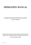
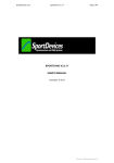
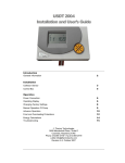
©2004 Dynojet Research, Inc. All Rights Reserved.
Control Panel Interface Upgrade Installation Guide For Model 200i and 250i Motorcycle
Dynamometers Serial Number 202xxxx.
This manual is copyrighted by Dynojet Research, Inc., hereafter referred to as Dynojet,
and all rights are reserved. This manual is furnished under license and may only be used
or copied in accordance with the terms of such license. This manual is furnished for
informational use only, is subject to change without notice, and should not be construed
as a commitment by Dynojet. Dynojet assumes no responsibility or liability for any error
or inaccuracies that may appear in this manual. Except as permitted by such license, no
part of this manual may be reproduced, stored in a retrieval system, or transmitted, in any
form or by any means, electronic, mechanical, recording, or otherwise, without the prior
written permission of Dynojet.
The Dynojet logo is a trademark of Dynojet Research, Inc.
Any trademarks, trade names, service marks, or service names owned or registered by any
other company and used in this guide are the property of their respective companies.
Dynojet Research, Inc., 2191 Mendenhall Drive, North Las Vegas, Nevada 89031, USA.
Printed in USA.
Part Number: 98123113 Version 1 (04/04)
April 12, 2004
Control Panel Interface upgrade for 200i/250i Dynos
Serial Number 202xxxx
These instructions are intended for use with installing the Control Panel Interface upgrade into Dynojet
Research model 200i and 250i dynos with a serial number prefix of 202. Before proceeding, check the
serial number on the dyno front left corner to verify it is in this range. The Dynojet part number for this
upgrade is P/N 78121003. If the serial number on your dyno does not start with 202 you will need a
different kit for the upgrade. Contact Dynojet with any questions.
This upgrade requires that your dyno has the optional monitor tray and upright arm to allow the mounting
of the Control Panel. If your dyno does not already have this option you will need to order it. Contact
Dynojet for the information. The part number and description for this option is P/N 61329110 Monitor Tray
and Upright Assembly.
This upgrade requires the altering of wiring that carries 240 volts during normal dyno operation. Failure to
follow these instructions could result in exposure to hazardous voltages or damage to your dyno. If you do
not feel that you can follow these instructions properly and safely, contact Dynojet.
Read all of these instructions before proceeding.
1. Unplug all power cords going into the dyno. This includes the main power cord and any additional
cords. Remove the carriage and the top cover on the carriage module. Remove the covers over the
retarder (if present) and the drum.
Remove Retarder
and Drum Cover
Remove carriage and
carriage module cover
Note: Dynojet recommends using a hardened 5/32-inch hex driver (such as Snap-On FA5E) to remove
the 1/4-inch screws. A standard allen key may round off in the shallow screw head.
1
2. Once the covers are off, inspect your dyno to verify that the starter brace is installed. If your dyno
does not have a starter brace, contact Dynojet. The starter brace can be ordered under the P/N
21721200 Starter Brace, M/C3. The starter brace supports the back of the starter and provides a
good ground connection.
Starter
Brace
3. If a battery is installed, disconnect the negative terminal of the battery first then remove the positive
terminal. If any battery charger has been installed, remove it. If you do not have a battery it will be
necessary to purchase one. The high current draw for the Wheel Clamp and the Motorized Carriage
is pulled from the car battery. The Control Panel Interface has a built in battery charger to recharge
the battery after each use. Refer to your dyno install manual for the battery specifications.
4. Remove the side door covering the Power Distribution assembly. If the Breakout board has
connections to the brake output pins on TB3, loosen the barrier strip connections and remove these
two wires.
Remove top 2 connections
on this barrier strip
2
5. Disconnect the red battery cable from the starter and the black battery cable from the ground
connection. If your dyno does not have a starter brace as shown, contact Dynojet. Disconnect the
starter solenoid wire. All wires should be removed from the starter. Disconnect the red and black
wires that go into the black box on the back wall of the drum module.
Remove
these wires
Disconnect
Yellow/Black
twisted wire
Remove Red
and Black wires
at other end
6. If the starter switch has been installed through one of the cable access holes, remove the cable
access plate and feed the starter switch back into the dyno and coil up in the front inside of the dyno.
This will not be used with the new hardware.
7. If your dyno has an air brake installed, trace the wires from the air brake solenoid to the black box.
Cut the black solenoid wires at the point where the wires are extended to connect to the black box. If
your dyno has an external switch attached to your dyno room door, disconnect it from the black box.
8. Remove the black box and the external starter switch.
3
9. Disconnect the white 4 pin connector from the DIN barrier strip rail on the back side of the Power
Distribution assembly to the lower fuse panel assembly. Disconnect the Air Pump power connector on
the front side of the Power Distribution assembly.
DIN barrier
strip
Fuse sub panel
Disconnect this
connector
10. Remove the two screws that hold the fuse sub panel in place then remove the panel and set aside.
Disconnect air
pump power cable
Remove
screw
Remove
screw
4
11. Disconnect the blue and brown wires that connect from the DIN barrier strip on the back of the Power
Distribution assembly from the 15A fan breakers. Pull only on the quick lug connectors on the back of
the breakers and take care to not pull on the wires. Do not disturb any other connections.
DIN
barrier
strip
15A
breakers
Disconnect
these wires
from the 15A
breakers
5
12. Remove the power supply bracket by cutting the cable ties and removing the two 8-32 screws from
the front side of the Power Distribution assembly and save for later use.
Power Supply
Bracket
13. Install the new power supply bracket, which has the power supply installed, with the two 8-32 screws
from the front side of the Power Distribution assembly.
6
14. Slide the Control Panel Interface board assembly into the rear of the Power Distribution assembly as
shown. Make sure to have the sheetmetal centered in the guides. Fasten the assembly in place with
two 8-32 x 3/8-inch screws in the back and two in the front.
8-32x3/8-inch
screws
8-32x3/8-inch
screws
15. Install the P/N 97422010 connector sticker to the front of the Power Distribution assembly.
7
16. Route the fan breaker and Control Panel Interface wires. You will need the wiring harness kit
P/N 76910601.
17. Connect the 5.5-inch blue wire labeled H to the lower left lug of the 15A circuit breaker.
18. Connect the 8-inch blue wire labeled I to the lower left lug of the upper 15A circuit breaker.
19. Connect the 6-inch brown wire labeled J to the top left lug of the bottom 15A circuit breaker.
20. Connect the 9-inch brown wire labeled K to the top left lug of the upper 15A circuit breaker.
K
I
J
H
Bottom
15A
breaker
21. Connect P/N 76950602 Control Panel Interface power supply cable to P9 on the Control Panel
Interface board – route behind the wires coming from the bottom of the DIN rail and between the top
and middle circuit breaker – connect to J1 and J2 on the power supply. Observe the locking tab on
the white connector. It needs to lock into place with the locking tab on the power supply connector.
The locking tab on the 3 pin connector at the top of the power supply should point down. The locking
tab on the 6 pin connector should point up.
Route
through here
P9
8
22. Connect the wires from the DIN power rail to the Control Panel Interface board.
23. Connect the brown wire from the bottom DIN terminal #1 to Tab 4 on the Control Panel Interface
board.
24. Connect the blue wire from the bottom DIN terminal #4 to Tab 3 on the Control Panel Interface board.
25. Connect the brown wire from the bottom DIN terminal #2 to Tab 2 on the Control Panel Interface
board.
26. Connect the blue wire from the bottom DIN terminal #5 to Tab 1 on the Control Panel Interface board.
Add cable ties as shown in the picture. Cut the cable ties flush.
#1
#5
Tab 2
Tab 4
Tab 3
Tab 1
9
27. Connect the brown wire from the top left connection of the lower 15A circuit breaker to Tab 8 on the
Control Panel Interface board.
28. Connect the blue wire from the bottom left connection of the lower 15A circuit breaker to Tab 7 on the
Control Panel Interface board.
29. Connect the brown wire from the top left connection of the upper 15A circuit breaker to Tab 6 on the
Control Panel Interface board.
30. Connect the blue wire from the lower left connection of the upper 15A circuit breaker to Tab 5 on the
Control Panel Interface board. Cable tie as shown. Cut the cable ties flush.
Upper
15A
Breaker
Tab 8
Tab 7
Tab 6
Tab 5
10
31. Route the wiring to the optional Wheel Clamp and Power Carriage through the dyno. You may find it
easier to slide the Stack Box out of the side of the dyno and remove its support bracket for routing
these cables. Even if you have not purchased these optional accessories it is better to install the
cables now for an easy upgrade in the future.
Remove
bracket
32. Remove the front cable access plate. Route the P/N 76950307 Pod to Clamp cable from P5 on the
Control Panel Interface board to the front cable hole on the dyno. The cable passes under the center
partition in the carriage module and in front of the vertical angle piece that forms the structure of the
front of the dyno. Make sure that the cable strain relief end with the conduit nut is at the end of
the cable that will connect to the Wheel Clamp.
P8 – Power
Carriage
connection
11
Control Panel
Interface
board
P5 – Wheel
Clamp
connection
33. Route the P/N 76950308 Pod to Carriage cable from P8 on the Control Panel Interface board to the
front cable hole on the dyno. The cable passes under the center partition in the carriage module and
in front of the vertical angle. Make sure that the cable strain relief end with the conduit nut is at the
end of the cable that will connect to the carriage. The strain relief for both the Power Carriage and the
Wheel Clamp must end up outside of the dyno.
Strain
relief
34. If you already had the serial cable to the PC routed through the front panel put it in with one of the
new cables and put the snap bushing around the cable. Install the cable pass through cover with the
two holes as shown.
12
35. Re-install the Stack Box support bracket with four ¼-20 x ½ -inch hex head bolts. Re-install the Stack
Box and secure with four ¼-20 x ½ -inch hex head bolts.
Support Bracket
36. Connect the P/N 76950403 Air Pump cable to P11 on the Control Panel Interface front side and route
the cable out the rear hole on the Control Panel Interface to the back of the dyno.
P11 Air
Pump supply
Air pump cable &
AFR sensor cable
Air pump cable &
AFR sensor cable
13
37. If you have an air brake, install P/N 76950110 cable into P7 in the Control Panel Interface board and
run the short cable to the Breakout board as shown and connect. Cable tie as shown and route the
other end to the air brake solenoid. Strip back the wires to the brake air solenoid and crimp into the
barrel connections on the P/N 76950110 Air Brake cable. If you do not have an air brake, then skip
installing this cable.
76950110 Air
Brake cable
Connect here
Strip back and crimp
to barrel connectors
14
38. Route the wire harness to the Control Panel assembly. Depending on the location of the monitor
upright, the wire harness can be routed to either side of the dyno. The P/N 76951501 cable plugs in
the Control Panel Interface board P4. This cable should be cable tied to the Power Distribution
assembly to make sure the cable does not pull on the board.
Cable
tie here
P4
39. If you do not have a monitor tray and stand it will be necessary to purchase one from Dynojet to
mount the Control Panel assembly. The cable bundle to the Control Panel needs to be run out the
cable access port by the monitor upright and a split bushing installed to protect the cable bundle.
Change the cable access plate for the one included in the kit with two holes. Route the pendant cable
through one split bushing and the cable to the Control Panel through the other.
15
40. Early production Monitor Arms, uprights, and the monitor tray may not have the tapped holes for
routing the Control Panel cables and mounting the Control Panel. If your monitor stand arms do not
have these holes, it will be necessary for you to drill and tap the holes in the monitor upright and the
arms to allow for attaching the Control Panel cable bundle. The cable bundle needs to be arranged
across the monitor arms to allow for easy movement of the monitor stand without pulling on the
cables. The following diagram shows where to drill and tap the holes in the monitor upright. Drill and
tap 8-32 holes in the arms about four inches in from each end.
16
41. The Control Panel needs to be disassembled so the cable to the Control Panel Interface can be
connected. Remove the screw and nuts shown and lift off the back/side cover.
Remove
nuts
Remove this
cover
Remove
these
screws
17
42. Connect the Control Panel cable to the Control Panel Button board. Cable tie the incoming cable as
shown.
Cable tie
here
43. Replace the Control Panel cover with the hardware that you removed before.
18
44. Mount the Control Panel to the side of the monitor tray. The cable lengths are set to allow installing
the Control Panel on either side of the monitor tray for easy access. Route the cable bundle along the
arms with service loops to allow movement. Make sure that during normal arm movement the cable
does not get pinched.
19
45. The battery cables and starter cables need to be connected next. The 4 pin connector plugs into the
back side of the Control Panel Interface board near the middle of the board to P2. The cable routes
out of the back of the Power Distribution assembly as shown.
P2
Route
here and
cable tie
Battery to Control
Panel Interface
cable
46. Install the starter support bracket, if necessary, and connect the other end of the battery cables to the
starter as shown.
20
47. Route the cables to the cable support bracket as shown. Cable tie as shown. Make sure that all of
the cables clear any moving components. Only connect the positive terminal on the battery at this
time. If this is the first time you have installed a battery in this dyno refer to the dyno install guide for
instructions on installing the battery hold down bracket.
Cable Support
Bracket
21
48. If you purchased either the Wheel Clamp or the Motorized Carriage, position the Motorized Carriage
motor and/or the Wheel Clamp close to the dyno and plug in their motor cables for testing.
22
49. If you have an air brake and your dyno room is equipped with a safety switch on the door, it is
necessary to connect the safety switch to the Control Panel Interface board interlock input to apply
the air brake whenever the dyno room door is open. Connect the wires feeding the switch contacts to
Interlock 1-A and Interlock 6-B connection points on the Control Panel Interface board. The board is
shipped with a jumper wire in this location. Remove the jumper wire and replace with the wires to the
door safety switch. This circuit must be closed for normal dyno runs.
Connect safety switch
wires here in place of
jumper
50. Connect the negative terminal on the battery. Plug the dyno in to the 240VAC single phase outlet.
-
23
51. Turn on the main breaker on side of the dyno by moving it to the up position. Make sure the E-Stop
button on the Control Panel is in the out position. Twist if necessary to take it out of E-Stop. Turn on
the switch on the front of the Stack box.
52. If you have the optional High Speed Blowers, verify they are plugged in to the sides of the dyno then
press the fan control buttons on the Control Panel and verify that the fans turn on and off. Press once
to turn on and once to turn off.
53. If you have the optional internal AFR pump installed, turn on the AFR pump and verify its operation.
Press once to turn on and once to turn off.
High Speed
Blower Control
AFR pump
24
54. If you purchased the optional Wheel Clamp then press the left hand clamp button and verify that the
Wheel Clamp closes. Release the button. Press the right hand clamp button first then press the left
hand clamp button and hold both buttons to open the clamp. Refer to the user’s manual for more
details of the operation.
55. If you purchased the optional Motorized Carriage then press the carriage forward and back buttons
and verify carriage movement.
Carriage
Control
Buttons
Wheel Clamp
Control Buttons
56. Turn off the dyno main breaker and unplug the dyno main power cord. Install the Control Panel
Interface drip cover with three 8-32 x ¼ -inch screws.
25
57. Install the door stop chain with the two 8-32 nuts.
58. Put the carriage module cover back on. Put the drum and retarder module covers back on. Install the
carriage.
59. Plug the dyno power cable in and turn on the main breaker on the power distribution assembly. Turn
on the power switch on the front of the stack box. Start up the WinPEP software and verify that the
program still communicates to the dyno hardware.
60. Press the starter switch and hold to verify starter operation. The speed indication in WinPEP should
show drum speed. Release the starter switch when the drum is up to top speed. Press the red
pendant button and verify that the dyno brakes or retarder do stop the dyno.
61. If you have the optional high speed blowers, turn then on and off to verify operation.
62. If you have the optional AFR integral pump, turn it on and off to verify its operation.
63. If you have the optional Motorized Carriage, run it back and forth to verify its operation.
64. If you have the optional Wheel Clamp either load a bike or put a bike wheel into the clamp and press
the left hand clamp button and hold until the clamp stops and the indicator light between the clamp
buttons is on steady. Press the right hand button first and hold then press the left hand button to
release the clamp. Refer to the user’s manual for more details on the operation.
65. If you have an air brake and a safety switch on the dyno room door then open the dyno room door
and verify that the air brakes do apply.
26