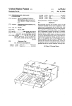
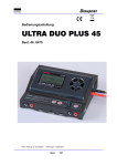
1
THINKING!
AHEAD
EPL !
SOLUTIONS INC.
SR-1 Precision
Camera / Sonde !
Cable & Pipe Locator !
User Manual
512Hz
SR-1 Precision
Introduction !
Congratulations on the purchase of your new SR-1 Precision Locator . The RS-1 Precision is specially
designed to pinpoint sewer lines (inspection camera transmitters & sonde) and detect buried power cables,
CATV cables, gas and water pipes, telephone cables, fiber optic cables with sheath.!
!
The Transmitter is a multi-frequency active signal generator . The Receiver is a multi-frequency locator
used to locate the relative position of inspection camera transmitters, sondes and buried utilities by active
signal or passive signals.!
DISCLAIMER OF LIABILITY!
EPL SOLUTIONS, INC SHALL NOT BE LIABLE TO DISTRIBUTOR, RESELLER, OR ANY OTHER
PERSON FOR ANY INCIDENTAL, INDIRECT, SPE- CIAL, EXEMPLARY OR CONSEQUENTIAL
DAMAGES, OR INJURY OF ANY TYPE WHATSOEVER, AND CAUSED DIRECTLY OR INDIRECTLY BY
PRODUCTS SOLD OR SUPPLIED BY EPL SOLUTIONS, INC !
!!
!!
!!
!!
!!
!!
!!
!!
!!
!!
!!
!!
!!
Prepare for Use!
Unpack your new SR-1 Precision Camera / Sonde, Cable and Pipe Locator . Make sure there is no
shipping damage and all the parts are included.!
!
Locate the battery compartment on the back of the Receiver and back of the Transmitter . Open the
compartment using a phillips screwdriver . Install the “C” batteries as marked.!
!
Locate the battery compartment on the back of the Transmitter . Remove the battery compartment door .
Install the “C” batteries as marked.
!!
!
THINKING!
AHEAD
Page 1
EPL !
SOLUTIONS INC.
(714) 453-9760
www.eplsolutions.net
!
SR-1 Precision
512Hz
Tip #1
Always keep the receiver
as vertical as possible
while performing a line
location. Waving the
receiver side to side will
produce inaccurate
locations.
ON/OFF Button!
Press the ON/OFF button to turn the Receiver on or off. Upon turning the
unit on, it will load the settings from the previous usage.!
Note: Unit will automatically shut off if no keys are pressed within a 10 minute
period. !
!
DEPTH Button!
Pressing the DEPTH button will cause the Receiver to first display the
depth measured. To change the Depth Measurement from English to
Metric, hold the Depth Key for ten seconds and the next setting will appear.!
!
Steps /Mode Button !
Used to change Sonde Locate (STEP -1 and STEP-2) or Line Trace (Peak,
Null. Pinpoint Peak)!
!
Freq. Button (*)!
Used to change locate frequencies. !
Sonde - 512Hz, 8KHz, 33KHz, 116KHz!
Line - 512Hz, 8KHz, 33KHz, 65KHz, 116KHz, RF, 60Hz!
(*)Press and hold for 5 sec. to turn on back lighting on/off!
!
Gain Buttons!
Adjusts the gain up or down . If the signal strength shows as “ --- ” on the
display, pressing the GAIN will automatically adjust to 85% on the scale
display .
!!
!
THINKING!
AHEAD
Page 2
EPL !
SOLUTIONS INC.
(714) 453-9760
www.eplsolutions.net
SR-1 Precision
How to pinpoint a camera sonde in three easy steps
with the SR-1 Precision
Step 1
peak -null- peak signal
Locate the sondes equator
PIPE
Locate the sondes poles
peak -null- peak signal
Step 2
PIPE
Equator and Poles located X marks the spot
PIPE
Step 3
Surface
Place SR-1 on the X. Push button depth
PIPE
!!
!
THINKING!
AHEAD
Page 3
EPL !
SOLUTIONS INC.
(714) 453-9760
www.eplsolutions.net
SR-1 Precision
Step 1 (S-1)
Press the Steps button so S-1 is displayed below the graph bar.
!
1.
!
!
!
!
!
!
Walk along the suspected path of the pipe. When you’re within proximity of the sonde,
your receiver will produce a tone that is known as a peak signal. When the receiver
passes over the equator of the Sonde the tone will suddenly become void which is
called a null.
You’re looking for a peak -null- peak signal when you are passing the Equator of the sonde during step 1.
3.
Place a marker on the surface where you just located your first null.
4.
Walk in a circular motion no more than 6ft towards the other side of the suspected path of the pipe. The receiver
will produce a peak -null- peak signal again when you pass over the other side of the sonde.
5.
Place a marker on the surface where you just located your second null and have completed step 1.
NOTES:
The receiver can be at any rotation along during Step 1.
The deeper or further away you are from the Sonde, the wider the peak -null- peak signal will be. Adjust signal strength
up or down with the gain control as needed to narrow your peak -null- peak signal . This step is usually performed only
for Step 1.
Le
f
.C
6 ft
Ri
gh
tS
id
pe
e
ak
-n
ul
lpe
a
k
ircl
e
Tip #2
A peak -null- peak signal will
be found along the equator line
from marker to marker.
tS
id
e
of
E
qu
at
or
of
E
qu
si
at
gn
or
al
Figure 1
Figure 2
!!
!
THINKING!
AHEAD
Page 4
EPL !
SOLUTIONS INC.
(714) 453-9760
www.eplsolutions.net
SR-1 Precision
Step 1 (S-1)
Pipe
When you can not get on both sides of the Equator? !
The Equator is a invisible straight line. Markings can be placed anywhere along
one side of the Equator to show this invisible straight line.
Area Not Accessible
6 ft. Circle
peak -null- peak signal
Pipe
Area Not Accessible
Figure 3
!!
!
THINKING!
AHEAD
Page 5
EPL !
SOLUTIONS INC.
(714) 453-9760
www.eplsolutions.net
SR-1 Precision
Step 1 (S-1)
When diving down on a 45º the Equator? !
Locating the Equator is no different than if the Sonde was laying flat. It is however necessary to go back
and adjust your location for pinpoint accuracy. !
!
This adjustment is performed only after completing all the steps. In Step 2 you will discover the Sonde is
not laying flat.!
!
After completing all the steps, calculate the depth into inches and divide by 2 as shown in Example 1. !
!
Location After!
Location Before!
4’-2” deep
25”
Surface
4’
-2
”=
50
”
Example 1!
4’-2” = 50”!
50” / 2 = 25”
Figure 4
!!
!
THINKING!
AHEAD
Page 6
EPL !
SOLUTIONS INC.
(714) 453-9760
www.eplsolutions.net
SR-1 Precision
Step 2 (S-2)
S-2
Press the Steps button so S-2 is displayed below the graph bar.
!
When the receiver is directly in front of or behind the Sonde the tone will
suddenly become void which is called a null. You’re looking for a peak -null- peak signal when you are
directly in front of or behind the Sonde during step 2.
!
1.
!
!
!
!!
Step 2ft. - 3ft. towards the front the sonde to locate the peak -null- peak signal as shown in figure 2.
A.
(For accurate peak -null- peak signal location in step 2 it’s best to have the receiver parallel to
the right and left side markers as shown in figure 2.)
2.
Place a marker on the surface where you located front null.
4.
With the receiver 2ft - 3ft. towards the back side of the sonde, look for a peak -null- peak signal again on
the back side of the sonde as shown in figure 2.
5.
Place a marker on the surface where you located back null.
NOTES:
The deeper or further away you are from the Sonde, the wider the peak -null- peak signal will be. Adjust signal
strength up or down with the gain control as needed to narrow your peak -null- peak signal .
!
a
pe
k
ea
-p
l
l
-nu
al
ign
s
k
2ft. - 3f
t.
Back
Pole
tor
ua
q
E
2ft. - 3f
t.
Front
Pole
tor
ua
q
E
a
pe
k
ea
-p
l
l
-nu
al
ign
s
k
Figure 5
!!
!
THINKING!
AHEAD
Page 7
EPL !
SOLUTIONS INC.
(714) 453-9760
www.eplsolutions.net
SR-1 Precision
Step 2 (S-2)
S-2
When you can not get on both sides Poles? !
The poles are a invisible straight line. Markings can be placed anywhere in front side or
the back side of the Sonde to show this invisible straight line.
peak -null- peak signal
Area Not Accessible
Figure 6
Pipe
Area Not Accessible
!!
!
THINKING!
AHEAD
Page 8
EPL !
SOLUTIONS INC.
(714) 453-9760
www.eplsolutions.net
SR-1 Precision
Step 2 (S-2)
When diving down on a 45º ? !
The Front Pole as shown will be a weaker and wider Peak-Null-Peak signal than the Back Pole.
Front
Pole
Back
Pole
Surface
Figure 7
!!!
EPL !
SOLUTIONS INC.
Page 9
(714) 453-9760
www.eplsolutio
SR-1 Precision
Step 3 Depth
!
With the receiver over Step 3 as shown in figure 3 push the depth measurement button
for the invert depth (bottom inside) of the sewer pipe.
NOTE:
For best depth measurement results, keep the receiver at a right angle to the step 1 side markers as
shown in figure 3.
tor
ua
q
E
Back Pole
Step 3
Front Pole
r
ato
u
Eq
Figure 8
!!
!
THINKING!
AHEAD
Page 10
EPL !
SOLUTIONS INC.
(714) 453-9760
www.eplsolutions.net
SR-1 Precision
Pipe
When you can not get over sonde on? !
Locate your Equator and Poles around all sides of the Sonde as shown if possible. If all
sides are not accessible move sonde backwards or forwards a few feet to confirm
location accuracy.
Area Not Accessible
6 ft. C
Figure 9
Area Not Accessible
Pipe
peak -null- peak signal
ircle
!!
!
THINKING!
AHEAD
Page 11
EPL !
SOLUTIONS INC.
(714) 453-9760
www.eplsolutions.net
SR-1 Precision
Circle
peak null- p
eak
peak -null- peak signal
How to locate a vertical sonde.!
1. Select Step-2. !
2. Walking in a circle and facing towards the center of the circle locate the 4 peak-nullpeak signals as shown. !
3. Confirm the accuracy of the locate by locating the 5th peak-null-peak signal in the
center as shown
k
pea
signal
pea
l
l
-nu
al
ign
s
k
Surface
Pipe
Figure 10
!!
!
THINKING!
AHEAD
EPL !
SOLUTIONS INC.
(714) 453-9760
www.eplsolutions.net
SR-1 Precision
Depth Measurement By Calculation !
(Horizontal Location Only!) (Depth Nulls are not to be confused with Front and Back Poles)!
Once the sonde has been located the depth can be checked for accuracy. !
1. Select Step-2. !
2. Moving the SR-1 towards the Front Pole keeping the SR-1 inline (as shown) locate and mark a
peak-null-peak signal (Depth Null A)!
3. Moving the SR-1 towards the Back Pole keeping the SR-1 inline (as shown) locate and mark a
peal-null-peak signal (Depth Null B)!
4. Measure the distance in inches between Depth Null A & B and multiply by .7!
!
Example: Distance between Depth Nulls A & B is 100” X .7 = 70” deep (surface to center of sonde)
peak -null- peak signal
peak -null- peak signal
100”
Surface
Front Pole
Back Pole
70”
!
Peak
Ghost Peak
Ghost Peak
Pipe
Depth Null!
A
Depth Null!
B
!!
!
THINKING!
AHEAD
Figure 11
EPL !
SOLUTIONS INC.
(714) 453-9760
www.eplsolutions.net
SR-1 Precision
How to locate a Deep (15- 25 feet plus)
sewer or drain line with the SR-1 Precision
Step 2
peak signal
Locate the sondes equator
peak signal
Step 1
Locate the sondes poles
Step 3
Push button depth
!!
!
THINKING!
AHEAD
EPL !
SOLUTIONS INC.
(714) 453-9760
www.eplsolutions.net
SR-1 Precision
How to locate a Deep (15- 25 feet plus)
sewer or drain line with the SR-1 Precision
Press the Steps button so S-2 is displayed below the graph bar.
!
1.
Step (S-2)
Walk along the suspected path of the pipe holding the receiver in line with the general direction of the path of the
pipe. When you’re within proximity of the sonde, your receiver will produce a tone that is known as a peak signal.
When the receiver passes over the equator of the Sonde a tone will found which is called a peak signal.
!
!
!
!
!
!
You’re looking for a peak signal when you are passing the Equator of the sonde during this step.
3.
Place a marker on the surface where you just located your first peak.
4.
Walk in a circular motion no more than 6ft towards the other side of the suspected path of the pipe. The receiver
will produce a peak -null- peak signal again when you pass over the other side of the sonde.
5.
Place a marker on the surface where you just located your second null and have completed step 1.
NOTES:
The receiver can be at any rotation along during Step 1.
The deeper or further away you are from the Sonde, the wider the peak -null- peak signal will be. Adjust signal strength
up or down with the gain control as needed to narrow your peak -null- peak signal . This step is usually performed only
for Step 1.
nal
sig ve
k
o
Le
ea
t p tly ab
ft
s
e
Si
ng direc
o
de
r
Tip
St hen
A peak signal will be found
w
of
along the equator line when
Eq
the SR-1 is in-line with the
ua
to
sonde.
r
Ri
gh
tS
id
e
pe
ak
si
gn
al
of
E
qu
at
or
Figure 1
1. Move slowly when locating deep.
2. Pay attention to the signal strength.
3. The signal will be strongest directly above the sonde.
!!
!
THINKING!
AHEAD
EPL !
SOLUTIONS INC.
(714) 453-9760
www.eplsolutions.net
SR-1 Precision
Step 1 (S-2)
S-1
1. Move slowly when locating deep.
2. Pay attention to the signal strength.
3. The signal will be strongest directly above the sonde.
A peak signal will be found when you are
above and in-line with the sonde with the
SR-1 as shown.
A null signal will be found above when the SR-1 is not
in-line (at a right angle) with the sonde as shown. This
step verifies that you are above the sonde.
!!
!
THINKING!
AHEAD
EPL !
SOLUTIONS INC.
(714) 453-9760
www.eplsolutions.net
SR-1 Precision
How to locate a Deep (15- 25 feet plus)
sewer or drain line with the SR-1 Precision
S-1
Step 1 (S-1)
Press the Steps button so S-1 is displayed below the graph bar.
!
When the receiver is directly in front of or behind the Sonde the tone will be a peak signal only when you
are directly in front of or behind the Sonde during step 1.
!
1.
!
!
!
!!
Step 3ft. - 4ft. towards the front the sonde to locate the peak signal as shown in figure 2. (For accurate
peak signal location in step 1 it’s best to have the receiver parallel to the right and left side markers as
shown in figure 2.)
2.
Place a marker on the surface where you located front null.
4.
With the receiver 2ft - 3ft. towards the back side of the sonde, look for a peak -null- peak signal again on
the back side of the sonde as shown in figure 2.
5.
Place a marker on the surface where you located back null.
NOTES:
The deeper or further away you are from the Sonde, the wider the peak -null- peak signal will be. Adjust signal
strength up or down with the gain control as needed to narrow your peak -null- peak signal .
!
al
ign
s
ak
pe
3ft. - 4f
t.
Back
Pole
tor
ua
q
E
Front
Pole
al
ign
s
ak
pe
tor
ua
q
E
Figure 5
!!
!
THINKING!
AHEAD
EPL !
SOLUTIONS INC.
(714) 453-9760
www.eplsolutions.net
SR-1 TX
Transmitter Controls and Indicators
SR-1 TX
TX OUTPUT JACK!
The Red/Black cord, Inductive Coupler connects here to create a direct connect or coupler inductive
circuit on the buried utility.!
!
TX ON!
Frequency and other LCD segments visible indicates unit is on .!
FREQUENCY SELECTOR!
Selects frequencies by toggle through available frequencies . 512Hz, 8kHz, 33kHz, 65kHz, 116KkHz are
standard on the SR-1 Tx .!
LOAD RATE INDICATOR!
The Load Rate Indicator symbol flashes to indicate signal transmission via coupler induction or direct
connection .!
OUTPUT SIGNAL LEVEL CONTROL!
The OUTPUT SIGNAL LEVEL CONTROL adjusts the power output from the Transmitter .!
RELATIVE RESISTANCE, VOLTAGE AND CURRENT METER!
The transmitter can display the resistance, voltage and amperage of the transmitted frequency . NOTE:
This is a relative measurement based on the feedback from the transmitted signal .
!!
!
THINKING!
AHEAD
EPL !
SOLUTIONS INC.
(714) 453-9760
www.eplsolutions.net
Plug the red/Black TesT cord into the TX OUTPUT JACK. Selec
Connect the red TesT cord to an existing
ground
point
or an exposed
metallic
section
Power
Output
Indicator,
Load Rate
Indicator
and the Frequen
of the utility . Place the Ground rod approximately 10 feet from this point, at an angle
Direct
Connection
of 90º to the buried
cable
or pipe. Push the Ground rod into the ground 8 to 10 Transmitter
inches.
Connect the Black TesTCAUTION
cord to the Ground rod.
CAUTION
DFF
F.1
F.2
kHz
mA
v
kM
SR-1 TX
!
DO NOT CONNECT TO LIVE OR
ALWAYS
TURN
OFF
TRANSMITTER
BEFORE
CONNECTING AND DISCONNECTING TEST LEADS
ENERGIZED POWER CABLES
Plug the red/Black TesT
cord into the TX OUTPUT JACK. Select
the FREQUENCY. The
cord connects to utility
Direct
Connection
is
the
most
reliable
method
of
signal
application.
Thisdisplayed.
method isRed
relPower Output Indicator, Load Rate Indicator and the Frequency
will be
(unbond this end for best results)
atively free of interference. The greatest amount of signal strength can be achieved by
this method. All frequencies
may be used. The far end of the utility must be grounded.
Transmitter
DFF
F.1
F.2
kHz
mA
v
kM
Connect the red TesT cord to an existing ground point or an exposed metallic section
of the utility . Place the Ground rod approximately 10 feet from this point, at an angle
of 90º to the buried cable or pipe. Push the Ground rod into the ground 8 to 10 inches.Buried Utility
to Locate
Connect the Black TesT cord to the Ground rod.
Far end o
buried utili
must be bon
Black cord connects
Red cord connects to utility
Plug the red/Black TesT c
ord into the TX OUTPUT JACK. Select
the FREQUENCY.
to transmitter
ground rod The
(unbond this end for best results)
Power Output Indicator, Load Rate Indicator and the Frequency will be displayed.
Flexicoupler Connection
Transmitter
DFF
F.1
F.2
kHz
mA
v
kM
The optional Flexicoupler and Hard coupler are very easy to u
Buried Utility
have to
be interrupted. The operation range is shorter than for
to Locate
ods.
The
tracing signal can be affected by neighboring cables
Direct Connection
Far end of
Black cord connects
to transmitter groundTrod
buried utility
esT cord or the Ground
rod are not needed for this method.
must be bonded
Successful
coupler
operation
requires
an insulated
Direct
Connection
is
the
most
reliable
method
of
signal
application.
The
greatest
amount
of signal
strength
can be conductor t
Flexicoupler Connection
near
andthe
far far
ends.
achieved by this method. All frequencies may be used. For best
results
end of the utility should be grounded .!
The optional Flexicoupler
andConnection
Hard coupler
are Fvery
easy to use, and services do not
Flexicoupler
Loop the
lexicoupler around the cable and connect the two
have
to
be
interrupted.
The
operation
range
is
shorter
for
Direct
Connection
methFlexicoupler
and Haround
ard
couplerthan
are
easy
to use,
services
do not
coupler
the
cable.
isandimportant
torod
connect the co
Connect the red cord to an existing ground pointThe
or optional
an exposed
metallic
section
of very
the
utility
.ItPlace
the Ground
have
toaffected
be interrupted.
The
operation range iscables
shorter than
for Direct
Connection
methods.
The
tracing
signal
can
be
by
neighboring
and
pipes.
The
r
ed/Black
needing
to
be
traced.
Connect
the
coupler
around
approximately 10 feet from this point, at an angleods.
of The
90o
to
the
buried
cable
or
pipe
.
Push
the
Ground
rod
into
the
ground the wire
tracing signal can be affected by neighboring cables and pipes. The red/Black
TesT cthe
ord or the Ground rod
are
not
needed
fornotthis
method.
TesT c
ord or
therod
G
round
needed
for this
method. ground. The result will be a strong
cable
not
near
the
system
8 to 10 inches . Connect
Black Test cord to the
Ground
.! rod are
Successful
coupler an
operation
requires an
insulated conductor
is grounded on on
bothboth
Successful coupler operation
requires
insulated
conductor
that that
is grounded
near and far ends.near the grounding, the range will also be shorter, and difficul
near
and
far
ends.
Loop
the Flexicoupler
around
the cable
andanother.
connect
the Power
two ends,Output
or clamp Indicator,
the Hard
one
cable
from
Plug the red/Black Test cord into the TX OUTPUT
JACK
. Select
the
FREQUENCY
. The
Load
coupler
around
the cable.
Itconnect
is important the
to connect
the
coupler around the cable
Loop
the Flexicoupler
around
the
cable
and
two
ends,
or
clamp
the Hard
Plug
the
c
oupler
T
esT
c
ord
into
the
TX
OUTPUT
JACK.
Always se
Rate Indicator and the
Frequency
will be displayed.
needing to be traced. Connect the coupler around the wire closer to the outgoing
coupler around the cable.
It not
is important
connect
the
around
the cable
cable
near the
system to
ground.
The
result
will be coupler
a stronger
signal.
By connecting
ignated
by
the
coupler.
The
most
common
is
the
82
kHz FREQ
near the grounding, the range will also be shorter, and difficulty may arise determining
needing to be traced. Connect
the available
coupler around the wire closer to the outgoing
in multiple frequencies.
one cable from another.
cable not near the system
ground.
result
willTX be
a JACK.
stronger
connecting
Plug
the couplerThe
TesT cord
into the
OUTPUT
Always signal.
select the By
frequency
designated by the coupler. The most common is the 82 kHz FREQUENCY,
but coupler are
Transmitter
near the grounding, the range
will
also
be
shorter,
and
difficulty
may
arise
determining
available in multiple frequencies.
one cable from another.
Plug the coupler TesT cord into the TX OUTPUT JACK. Always select the frequency designated by the coupler. The most common is the 82 kHz FREQUENCY, but coupler are
Inductive Coupler
available in multiple frequencies.
Wraps Utility
Red cord connects to utility
(unbond this end for best results)
Buried Utility
to Locate
Far end of
buried utility
must be bonded
Black cord connects
to transmitter ground rod
DFF
F.1
F.2
kHz
mA
v
kM
Transmitter
DFF
F.1
F.2
kHz
mA
v
kM
Inductive Coupler
Wraps Utility
Transmitter
Direct Connection
CAUTION
CAUTION
DFF
F.1
F.2
kHz
Buried Utility
to Locate
mA
v
kM
Near End of
Buried Utility
Must Be Bonded
Far End of
Buried Utility
Must Be Bonded
DO NOT CONNECT TO LIVE OR
Inductive Coupler Connection
InductiveACTIVE
NEVER
BOND
ENERGIZED
POWERCoupler
CABLES POWER CABLES
Wraps Utility
!
CAUTION
Buried Utility
to Locate
Near End of TURN OFF TRANSMITTER
Far End of
ALWAYS
BEFORE
Buried Utility
Buried Utility
CONNECTING
AND DISCONNECTING
TEST LEADS
Must Be Bonded
Must Be Bonded
Direct Connection is the most reliable method of signal application. This method is relatively free of interference. The greatest amount of signal strength can be achieved by
800.851.7347 www.rycominstruments.com
into
the TX OUTPUT
JACK . The Inductive Coupler performs at 8kHz, 33kHz, 65kHz
this method. All frequencies may be used. The far end of the utility must be grounded.
Plug the Inductive Coupler cord
116kHz frequencies. The most commonly used is 65kHz.Buried
! Utility
&
4
Connect
the red TesT cord to an existing ground point or an exposed metallic section
to Locate
this point, at an angle
ground
8 to 10 inches.
and services do not have to be interrupted . The
operation
range
of the utility . Place the Ground rod approximately 10 feet from
Near End of
Far End of
of 90º to the buriedBuried
cable
or pipe. Push the Ground rod into the
Buried Utility
Utility
Connect the BlackMust
TesTBec
ord to the Ground rod.
Must Be Bonded
Bonded
The optional Inductive Coupler is very easy to use,
is
800.851.7347
shorter than for Direct Connection methods
and the tracingwww.rycominstruments.com
signal can be affected by neighboring cables and pipes. !
Plug the red/Black TesT cord into the TX OUTPUT JACK. Select the FREQUENCY. The
Power Output Indicator, Load Rate Indicator and the Frequency will be displayed.
It is best to use the Inductive Coupler around a group of LIVE CABLES needing to be traced, the result will be a stronger
signal . Connecting the Inductive Coupler around PIPE AND CONDUIT, DISCONNECTED OR INACTIVE CABLES, will
produce poor results and difficulty will arise. !
Transmitter
DFF
F.1
F.2
kHz
mA
v
kM
800.851.7347
www.rycominstruments.com
Red cord connects to utility
(unbond this end for best results)
Note:!
When a ground wire is present it is always best use the Direct Connection Method only after the ground wire has
4
been checked for an absence of power with a voltage meter.
Buried Utility
to Locate
Flexicoupler Connection
Black cord connects
to transmitter ground rod
Far end of
buried utility
must be bonded
The optional Flexicoupler and Hard coupler are very easy to use, and services do not
have to be interrupted. The operation range is shorter than for Direct Connection methods. The tracing signal can be affected by neighboring cables and pipes. The red/Black
TesT cord or the Ground rod are not
needed for this method.
THINKING!
Successful coupler operation requires an insulated conductor that is grounded on both
AHEAD
near and far ends.
Loop the Flexicoupler around the cable and connect the two ends, or clamp the Hard
coupler around the cable. It is important to connect the coupler around the cable
needing to be traced. Connect
the coupler
around the
wire closer to the outgoing
(714)
453-9760
www.eplsolutions.net
cable not near the system ground. The result will be a stronger signal. By connecting
near the grounding, the range will also be shorter, and difficulty may arise determining
one cable from another.
Plug the coupler TesT cord into the TX OUTPUT JACK. Always select the frequency designated by the coupler. The most common is the 82 kHz FREQUENCY, but coupler are
!!
!
EPL !
SOLUTIONS INC.
SR-1 TX
Selecting A Trace Signal Frequency
The choice of 512Hz, 8kHz, 33kHz, 65 kHz and 116kHz Frequency is dependent on the conditions of the locate .!
The 512 Hz, 8 kHz, 33kHz, 65kHz and 116 kHz signals each have their advantages . It is recommended to begin by using
the 8 kHz signal, and continue as long as you are confident in the results . If the signal is very weak try to adjust the
connection or grounding . If there is no improvement in signal then try 33kHz. Repeat adjustments of ground and
connection point again until switching to 116kHz. The 512Hz signal 8 kHz and 33kHz takes the best of both high and low
frequency.!
!
512Hz (lower frequency) !
• Signal is usually preferred for a loop trace. !
• Has a long locating range. !
• Not very susceptible to bleed off or coupling!
• Less likely to jump impedance on the utility than mid-range and high-range frequencies.!
• Susceptible to locating errors caused by nearby high voltage electrical cables (50Hz- 60Hz). !
• Will not travel well through disconnected shield bonds or insulated pipe bushing .!
!
8 kHz (mid-range frequency) 33kHz (high frequency)!
• Less susceptible to locating errors caused by nearby high voltage electrical cables (50Hz- 60Hz).!
• Has a better locating range than higher frequencies.!
• Not very susceptible to bleed off or coupling!
• Less likely to jump impedance on the utility than high-range frequencies.!
• Mid range frequency is not very susceptible to bleed off or coupling but can jump impedance on the utility better than the
512 Hz!
• 8 kHz is one of the most common frequencies used to locate coaxial cable and telecom pairs .!
!
65kHz and 116kHz (high frequency) !
• Less susceptible to locating errors caused by high voltage electrical cables (50Hz- 60Hz) .!
• Locating range is shorter than the 512Hz, 8kHz and 33kHz signal . !
• 65 kHz (higher frequency) is sometimes better than the 8kHz (mid-range frequency) and 33kHz (high frequency) for
locating sharp corners in cables or pipes.!
• 65kHz and 116kHz signal is also better for “jumping” disconnected shield bonds or grounds, or tracing signal may indicate
one of these characteristics. !
• The locating range is quite short for the 116kHz signal so the Transmitter must be repositioned more often during the
tracing operation. !
• High Frequencies are useful for applying a signal using the Inductive Coupler.
!!
!
THINKING!
AHEAD
EPL !
SOLUTIONS INC.
(714) 453-9760
www.eplsolutions.net
ti
u
r
a
r
l
e
u
t
s
t in ood in
o
n
are
e g
v
s
a
e
h
lose
t
s
rvic
c
u
e
SR-1 TX
s
s
a
e m ort.
nd
ide
p
i
a
s
THE
p
,
s
F
h
T
r
i
e
s
s
O
o
n
u
be
le
o
l
n
IDE
l
r o
t
b
i
e
e
S
T
a
t
w
h
T
i
t
c
n
e
m
e
,
h
e
l
s
ul
nt
The g rang
en i
N
ran
o
T
.
r
e
d
S
T
the
e
T
Inductive
Coupler
Connection
e
i
n
W
i
c
y
d
t
m
a
s
O
l
b
e
a
. P
ne
per
ARR ad Tran arried
n
o
o
t
e
t
e
h
u
h
ro
l c
nt
b
a
g
i
n
l
Hzandbservices
e
, or t This method is convenient2 tokuse,
g
A
h
i
s
interrupted
test cordseor connections
are needed . The cable
8
torethet. No
h
ipe. are lnot
a
e
t
c
h
or pipe must have
good insulationr orp
non-conductive
coating,
operating
range
will
be
short
.!
r
t
o
90
g fo
ress cable o e. First,
n
e
i
P
k
h
.
t
o
N
o 65kHz & 116kHz frequencies. The most commonly
n is na
the SR-1
are l33kHz,
iused
h
e
r O Turn
theTX ONle. TheoInductive
l
r pip frequencies
i
c
f
r
h
65kHz.
!
o
sig
a
w
e
e
S
h
.
t
r
path the cab le path
e
If or pipe.! signa
T
.cable
h
smatiTa 15º angle
Place
SR-1 TX on its
side
. Align the ARROWS on the SIDE OF THE TRANSMITTER
totthe
b
n
a
h
a
a
t
i
p
c
ng
Tr
e
o
r
d
e
h
t
t
e
s
h
ne w Startetracing
t
t
t as shown
c the path with the receiver 25 feet from the SR-1
TX
45º
of either side of the
m. Search infthe
lasutility
low
l
p
o
r
x
o
e
f
e
h
t
t TX to a point 25 feet
Locate the cable or pipe, and follow the path
becomes
move d
he below.
fee. If.! the signal
and weak,eh
n the SR-1
i
,
5
behind the last strong signal, and continue
searching
2
e
r
tb
pip
e
eive
r
e
c
o
f
e
r
ble oint 25
e
h
a
t
c
p
with te the
a
h
o
t
t
a
ack
a
tter P y
i
m
he p ve. Loc ransmiTTer
s
an
lit
On Tr o the Uti
o
T
s
b
w
o
T
e
Arr
llel
n a
e th
Align and Para
v
o
e
Abov
ak, m hing.
arc
e
s
e
y
Utilit
Direc
ARR
PLACE
LE PATH
NG CAB
E
MOD
OW ALO
UCTIVE
FOR IND
TX
SR-1mitter
25’
15º
tion
Utility!
Direction
s
Tran
45º
side
r Out itter
e
v
i
e
sm
Rec
With m the Tran tility
y
t
i
l
i
Fro
e Ut
of U
Locat ot Radius ither Side
5 Fo
of E
of a 2 ithin 45º
and W
if
e
r
a
t aw d th
o
n
or is iTTer an
t
a
r
spe
pe
nsm
o
e
a
r
e
m
T
sa
if th e. The
e
h
d
t
o re
e
i
t
s
u
d
u
a
q
u
i
s
s
es i s techn or walk es an a
u
q
i
t EPL r! giv
THINKING!
thi
raAHEAD
c hn
!
r
e
e
o
t
p
f
ive
o ! eceSOLUTIONS
r.
g
d
n
TeINC.
i
h
e
T
t
i
c
d
a
m
r
a
s
e
!
loc
nee ther. E
h
ran
t
T
h
e
r
n
c
e
r
453-9760
www.eplsolutions.net
th
ea
le a ach o er. Whe a(714)
S
d
p
n
o
d
n
e
e
li
r
p
m
oth
o
eive
o
r
h
c
w
f
e
T
c
ea
ists.
way
he r
SR-1 Precision
How to locate cable or pipe using the SR-1 Precision
Locating Cable Locating
or Pipe
the Cable or Pipe
Locating the Cable or Pipe
Make sure the TransmiTTer is connected and in the ON position. Then move approximately 15 feet (4.
Make sure Make
the SR-1
TXthe
signal
generator
is connected
andininthe
theON
ONthe
position
Thenmove
move
approximately
.5 the Inductive
sure
TransmiTTer
is connected
and
position.
approximately
15 feet
feet(4(4.5
meters)
away
from
the TransmiTTer
along
path..Then
(Move
about
25 feet (7.5 15
meters)
for
meters) away
for conductive
search
mode
from
the
SR-1
TX
signal
generator
along
the
path
.
(Move
about
25
feet
(7
.5
meters)
awaysearch
from
the
T
ransmiTTer
along
the
path.
(Move
about
25
feet
(7.5
meters)
for
the
Inductive
mode.)
meters) forsearch
the Inductive
search mode.)!
mode.)
Hold the receiver so that you can see the LCD bargraph and controls easily. Make sure the receiver and
HoldPrecision
the receiver
that
can
LCD
bargraph
controls
easily.
Make
sure sure
the Hz
rthe
eceiver
and
Hold the SR-1
Receiver
soyou
that
you see
can the
seeare
theboth
LCD
bar-graph
controls
easily
. either
Make
Receiver
the so
TransmiTTer
FREQUENCY
set
for and
the and
same
FREQUENCY,
815
(lower),
8 kHz, 33kHz o
the
T
ransmiTTer
FREQUENCY
are
both
set
for
the
same
FREQUENCY,
either
815
Hz
(lower),
8
kHz,
33kHz
or
and the Transmitter FREQUENCY
are both
for the
FREQUENCY,
either
512 Hz
8 kHz,
82 kHz (higher).
Orset
select
thesame
passive
locating mode
which
do(lower),
not require
the(mid-range)
transmitter
82 kHz
(higher).
Or select the
locating
mode
which
do not
transmitter
33kHz, 65kHz
or 116kHz
(high-range)
. Orpassive
select the
passive
locating
modes,
RFrequire
or 60Hzthe
which
do not require a
Selecting
the
Locating
Mode
(Peak
or
Null)
transmitter.!
Selecting the Locating Mode (Peak or Null)
Press the MODE button to select the desired Peak or Null locating method.
Selecting the
Locating
Mode
(Peak,
Sharp the
Peak
or Null,
Target
Null)!
Press
the MODE
button
to select
desired
Peak
or Null
locating method.
Press the MODE button to select the desired Peak or Null locating method .
Peak Mode
Receiver Max
Null Mode
Receiver Min
Peak Mode
Receiver
Max over cable
Null Mode
Receiver
Min over cable
Signal
Signal
Signal over cable
Signal over cable
Buried cable
Buried cable
(End view)
(End view)
Buried cable
Buried cable
(End view)
(End view)
Peak Locating Mode
Peak Mode Locating
Peak Mode Locating
Keep the receiver in a vertical position . Move the receiver left to right across the path . When the receiver is directly
Keep the receiver in a vertical position. Move the receiver left to right across the path. When the receiver
above the cable
pipe,
rotate
receiver
for a maximum
signal
. As left
you move
receiver
away When
from the
path,
Keep or
the
receiver
in the
a vertical
Move
the
rrotate
eceiver
rightthe
across
the path.
thecable
receiver
is directly
aboveposition.
the cable
or pipe,
the rto
eceiver
for a maximum
signal. As
you
move the receiver
the meter reading
(and
audio
frequency
response)
will
drop
off
.!
is directly above
thefrom
cable
pipe, path,
rotatethe
themeter
receiver
for a maximum
signal.
As youresponse)
move thewill
receiver
away
theorcable
reading
(and audio
frequency
drop off.
away from the cable path, the meter reading (and audio frequency response) will drop off.
If you rotate the receiver Ifwhile
the the
cable,
a sharp
NULL
will the
identify
the cable’s
when
aligned
the flat
youover
rotate
receiver
while
over
cable,
a sharpdirection
NULL will
identify
thewith
cable’s
direction. It is
you rotate aligned
the receiver
while
over
the
cable,
a
sharp
NULL
will
identify
the
cable’s
direction.
It is
side of the Ifreceiver.
with the flat side of the receiver.
aligned with the flat side of the receiver.
Tip #1
Always keep the receiver
as vertical as possible
while performing a line
location. Waving the
receiver side to side will
produce inaccurate
MAXIMUM
locations.
RECEIVER
SIGNAL
CABLE
PATH
MAXIMUM
RECEIVER
SIGNAL
CABLE
PATH CABLE
PATH
CABLE
PATH
NULL SHOWS
NULL SHOWS CABLE
CABLE
DIRECTION
DIRECTION
!!
!
THINKING!
AHEAD
EPL !
SOLUTIONS INC.
(714) 453-9760
www.eplsolutions.net
SR-1 Precision
Peak Locating Mode continued
Trace the path by walking away from the transmitter at a moderate pace. Move the receiver to the left and right while
walking, following the PEAK signal .!
!
As you trace the path, the PEAK meter reading may slowly fade as you move away from the transmitter. Press and
release the GAIN buttons as needed to compensate for changes in level (higher or lower). One of the following may
occur:!
• a junction where the signal divides and goes several directions. !
• a break in the cable or shield.!
• a change in the depth of the cable or pipe. d) an insulated pipe fitting.!
• a slack loop of cable.!
If you can no longer trace the path, even with the GAIN set to maximum, connect the transmitter to the far end.of the path
and trace back to the point where you lost the signal.!
!
Mark the straight sections of the path every few feet. Mark sharp curves, loops, and cable bundles every foot or so. Sharp
changes in the path cause the receiver PEAK and NULL indications to behave differently than when tracing a straight
path. Practice on the path that you know has turns and laterals in it. This will help you to recognize the conditions within
the field.
Null Locating Mode
Move the receiver left to right across the cable path. When the receiver is directly above the cable or pipe, a NULL (lowest
meter reading and lowest audio tone) will occur. When moving the receiver to left or right of the NULL point, the meter
reading will rise to a maximum point (PEAK). The audio tone will also be at its. highest pitch. When the receiver is moved
beyond the PEAK, the meter reading will begin to fade.!
Trace the path by walking away from the transmitter at a moderate pace Move the receiver to the left and right when
walking, following the NULL indications.!
As you trace the path, the PEAK meter reading may slowly fade as you move away from the transmitter. Press and
release the GAIN buttons as needed to compensate for changes in signal level. If the PEAK meter readings suddenly
changes in level (higher or lower), one of the following may have occurred:!
• a junction where the signal divides and goes several directions. !
• a break in the cable or shield.!
• a change in the depth of the cable or pipe. !
• an insulated pipe fitting.!
• a slack loop of cable.!
!
If you can no longer trace the path, even with the GAIN control set to maximum, connect. the transmitter to the far end of
the path, and begin tracing the path back.!
Mark the straight section of the path every few feet. Mark sharp curves, loops, and cable bundles every few inches. Sharp
changes in the path causes the receiver PEAK and NULL. indicators to behave differently than when tracing a straight
path. Practice on the path that. you know has turns and laterals in it.This will help in recognizing the conditions within the
field .
!!
!
THINKING!
AHEAD
EPL !
SOLUTIONS INC.
(714) 453-9760
www.eplsolutions.net
SR-1 Precision
Absolute Signal Strength
The SR-1 Precision Receiver provides the operator with a direct measurement of the receiver’s signal strength. The
measurement is displayed with three numerical digits (ex:485) located at the top of the LCD display. The measurement
range is from 0 to 999 indicating a very week signal (0) to a very strong signal (999). Absolute Signal Strength is
independent of the GAIN setting. or meter reading. It gives the operator information about the actual amount of signal
being radiated from the conductor and received by the receiver .!
Measuring Absolute Signal Strength at any time is done by reading the number at the top. of the LCD display. The
Absolute Signal Strength will not be displayed if the meter reading is. too high or too low. Adjust the GAIN to move the
meter reading to mid-scale.The numerical display will change from ‘---’ to a valid measurement.!
Absolute Signal Strength measurements are more sensitive to signal changes than the meter display PEAKS and NULLS
can be more precisely pin-pointed.This measurement can also be used to monitor signal loss as the conductor is being
traced.
Absolute Signal Strength
The GAIN up and down buttons are used to increase and decrease the gain in small. amounts.If the meter reading is
very low, pressing the GAIN up button will center the meter reading to midscale. Likewise, if the meter reading is very
high, pressing the GAIN down button will center the meter reading to midscale.
Passive 50Hz / 60Hz ~ Locating
The SR-1 Precision Receiver is capable of locating power utility frequencies. This MODE is useful for locating
underground primary and secondary power utilities. In certain circumstances, this MODE will also locate water pipes,
sewer lines, cable television, and telephone.The reason is that common electrical grounds are sometimes found among
these various utilities Select the 50/60~ (Hz) frequency on the receiver. Select 60Hz mode. The SR-1 will locate conductor
using the Sharp PEAK mode.!
This method is useful because of its speed and convenience. Start at a known reference point and keep in mind that other
conductors in the area may produce this same locating signal.!
The SR-1 TX transmitter is not required to locate in this mode.
Passive Radio Frequency Locating
The SR-1 Precision Receiver is capable of passively locating metallic utilities where radio frequencies have coupled to the
utility. This mode is useful for sweeping a green area for utilities. In certain circumstances, this mode will locate water
pipes, cable television, gas lines and telephone. This locating option does not always detect buried utilities even when
radio frequencies are present.This.method is useful because of its speed and convenience. Start at a known reference
point and keep in mind that other conductors in the area may produce this same locating signal .!
The SR-1 TX transmitter is not required to locate in this mode.
!!
!
THINKING!
AHEAD
EPL !
SOLUTIONS INC.
(714) 453-9760
www.eplsolutions.net
SR-1 Precision
Push Button Depth
The only way to be sure of the depth of a utility is to exposes the utility. !
At any given time, the depth readout may be inaccurate.!
!
!
The SR-1 Precision Receiver can measure depth with the push of a button. The depth is displayed at the top of the LCD
display in feet and inches. Push button depth is useful in quickly determining the depth of the utility during path locating.!
Begin this measurement by locating the path of the cable or pipe. Move to the location where you want to measure the
depth. Stay at least 15 feet (4 .6 . meters) away from the SR-1 TX transmitter. Pin-point this location as accurately as
possible (see Peak Mode Locating page, Null Mode Locating page and Absolute Signal Strength page). Place the
receiver vertically over the conductor and rest the foot of the locator on the .ground. While holding the receiver vertical,
press and release the DEPTH.button.The receiver will briefly indicate a measurement is being performed and then display
the depth at the top of the LCD .display.!
!
Caution must be exercised when using the push button depth feature, as tilted magnetic fields and adjacent conductors
can significantly influence this measurement. The operator should periodically check for adjacent conductors and tilted
magnetic fields when taking.push button depth readings. For information on identifying tilted magnetic fields, refer to
Tilted Magnetic Field Identification and Depth Measurement 45º Method.!
!
Note: !
The SR-1 Precision Receiver is designed to alert the operator of potential current and depth measurement errors . If the
display reads ‘Err’ during a current and depth measurement, the receiver has.detected a condition that could produce
inaccurate readings.!
!
!
Errors can exist when the conductor signal flow is too small. Check SR-1 TX transmitter hookup and far end access point
for poor connections. This.cause of error can be identified by a high.GAIN setting (80 or greater on the bar-graph display).!
The receiver may also be detecting adjacent cables or is not directly over the target conductor. Verifying target conductor
path precisely before measuring current again.!
If at anytime the display reads ‘CAL’, .contact EPL Solutions, Inc at (714) 453-9760.
Current Measurement
The SR-1 Precision Receiver later models contain a feature that is very useful in identifying a desired cable in a field of
various conductors and/or utilities. !
It is not unusual for the target conductor (the conductor connected to the SR-1 TX transmitter) to induce a signal into
nearby conductors in a crowded field. In these instances, the radiated signal on the conductors close to the surface of the
earth, may be stronger than the transmitter signal on the target conductor buried deep in the ground. !
The operator will find two or more paths and must determine which is the target conductor. By using the current
measurement feature of the SR-1 Precision Receiver, the operator can determine the amount of 512 Hz, 8kHz, 33kHz
65kHz or 116kHz current flowing on the conductors, regardless of the depth. !
The highest current flow indicates the target conductor.
!!
!
THINKING!
AHEAD
EPL !
SOLUTIONS INC.
(714) 453-9760
www.eplsolutions.net
and Within 45º of Either Side of Utility
SR-1 Precision
Blind Search
d Search locating techniques is used if the operator is not aware
. TwoThepeople
aretechniques
needed
foroperator
thisis not
technique.
ransmiTTer
and
Blind Search locating
is used if the
aware if a buried utilityThe
exists . T
Two
people are
for this technique . Using 65kHz keep the Transmitter and the Receiver 25 feet away from each other . Each
feet needed
away
from each other. Each operator walks at the same sp
operator walks at the same speed keeping a distance of 25 feet from each other . When the receiver gives an audio
response, then a buried utility is present between the Receiver and the Transmitter.
e of 25
feet from each other. When the receiver gives an audio re
utility is present between the receiver and the TransmiTTer.
Inductive Connection
This method is convenient to use, and services are not interrupted. No test cords
or connections are needed. The cable or pipe must have good insulation or nonconductive coating, or the operating range will be short.
Turn the TransmiTTer ON. Press the 82 kHz button. Place TransmiTTer on iTs side as close
as possible to the path of the cable or pipe. Align the ARROWS on the SIDE OF THE
TRANSMITTER in line with the cable or pipe. First, locate the broad TransmiTTer Null, then
move toward the expected cable path while looking for the signal carried by the
cable.
65kHz
Start tracing the path with the receiver 25 feet from the TransmiTTer. Search in the 90º
zone as shown above. Locate the cable or pipe, and follow the path. If the signal
becomes weak, move the TransmiTTer to a point 25 feet behind the last strong signal,
and continue searching.
65kHz
TRANSMITTER
Align Arrows On Transmitter Pack
Above and Parallel To the Utility
25’
PLACE ARROW ALONG CABLE PATH
FOR INDUCTIVE MODE
45º
DFF
F.1
F.2
8869
Utility
Direction
Transmitter
kHz
mA
v
kM
Locate Utility With Receiver Outside
of a 25 Foot Radius From the Transmitter
and Within 45º of Either Side of Utility
Blind Search
The Blind Search locating techniques is used if the operator is not aware if a buried utility exists. Two people are needed for this technique. The TransmiTTer and the receiver are
Held 25 feet away from each other. Each operator walks at the same speed keeping a
distance of 25 feet from each other. When the receiver gives an audio response, then a
buried utility is present between the receiver and the TransmiTTer.
TRANSMITTER
DFF
F.1
F.2
8869
kHz
mA
v
kM
25 Feet (7.5 Meters) Between Transmitter and Reciever
25 Feet (7.5 Meters) Between Transmitter and Reciever
RECEIVER
800.851.7347
www.rycominstruments.com
5
RECEIVER
!!
!
THINKING!
AHEAD
EPL !
SOLUTIONS INC.
(714) 453-9760
www.eplsolutions.net
SR-1 Precision
Tilted Magnetic Field Identification
When adjacent cables or pipes are present, they will sometimes create locating errors. Some of the SR-1 TX transmitter
signal is picked up by the adjacent conductors and is redirected so that it combines with the original signal. The result is a
Tilted Magnetic Field.This is often the reason that numeric depth readouts.are sometimes created in error.!
The operator can verify the accuracy of path locate by performing the 45º Angle Method locate and the Depth
Measurement Calculation. If readings agree to within 5 inches, the path locate is accurate. !
If the two depth readings do not agree, then dig with care A closer locate would be halfway between the two outside
depth locate marks !
This is an important technique that should be used to ensure the most accurate location possible.
Depth Measurement 45º Angle Method
Move to the location you want to measure depth. Stay at least 15 feet away from the SR-1 TX transmitter. With the SR-1
Precision Receiver in Peak Mode sweep the receiver left to right across the path until the utility is located. Mark the path
on the ground as precisely as possible using the Peak Locating Method.!
The Depth measurement 45º Angle Method should be performed at different areas along the path of the utility and is
effective for checking accuracy of location.!
Place the receiver on the ground with.the LCD meter facing up. Position the unit so that the BUBBLE LEVEL (if equipped)
on top of the meter is centered(45º). Pull the receiver away from the cable path (at 90º to the cable path) keeping the
BUBBLE LEVEL (if equipped) centered. When the receiver indicate. a Peak-Null-Peak signal, mark the location of the
receiver’s foot. The distance between the receiver and the cable path is the depth of the pipe or cable.!
A false depth reading may be caused by nearby buried metallic objects, such as a second cable, pipe, sewer, fence or
railroad track. Confirm the depth measurement by repeating. the above steps on the opposite side of the pipe or cable.!
A variance greater than 5 .inches in depth measurement may indicate the presence of additional buried cables, pipes or
other objects.
!!
!
THINKING!
AHEAD
EPL !
SOLUTIONS INC.
(714) 453-9760
www.eplsolutions.net
SR-1 Precision
Depth Measurement Calculation
Move to the location you want to measure depth. Stay at least 15 feet away from the SR-1 TX transmitter. With the SR-1
Precision Receiver in Peak Mode sweep the receiver left to right across the path until the utility is located. Mark the path
on the ground as precisely as possible using the Peak Locating Method.!
The measurement calculation should be performed at different areas along the path of the utility and is effective for
checking location accuracy because it is unlikely to have the signal distortion in each direction of the utility path.!
Adjust the gain up so the bar-graph is at the 100%. Move left of utility until the bar-graph drops to 50% and mark this
point. Perform the same to the right of the utility. They should be about equal distance from center. Measure the distance
from both marks, they should be twice the depth of the utility.
2
d
!!
!
THINKING!
AHEAD
EPL !
SOLUTIONS INC.
(714) 453-9760
www.eplsolutions.net
SR-1 Precision
Two-Thirds Plus One Third Rule
When adjacent cables or pipes are present, they will sometimes create locating errors. Some of the SR-1 TX transmitter
signal is picked up by the adjacent conductors and is redirected so that it combines with the original signal. The result is a
Tilted Magnetic Field.This is often the reason that numeric depth readouts are sometimes created in error.!
The operator can verify the accuracy of path locate by performing the Two-Thirds Plus One Third Rule.!
!
Move to the location you want to measure depth. Stay at least 15 feet away from the SR-1 TX transmitter. With the SR-1
Precision Receiver in Peak Mode mark the path on the ground as precisely as possible using the Peak Locating Method.!
With the SR-1 Precision Receiver in Null Mode mark the path on the ground as precisely as possible using the Null
Locating Method.!
If the Peak and Null marks are the agree (in the
precise.!
same location) it can be assumed you location is accurate and
The location is not accurate and precise if the Peak and Null marks do not agree. Both marks will show the error on the
same side of the utility. True utility line position will be close to the peak location. The utility line is half as far to the side of
the peak position as the distance between the
Peak and Null.
True Position
!!
!
THINKING!
AHEAD
EPL !
SOLUTIONS INC.
(714) 453-9760
www.eplsolutions.net
SR-1 Precision
Notes:
!!
!
THINKING!
AHEAD
EPL !
SOLUTIONS INC.
(714) 453-9760
www.eplsolutions.net
SR-1 Precision
EPL Solutions, Inc.
Orange, CA
714-453-9760
www.EPLSolutions.net
[email protected]
!!
!
THINKING!
AHEAD
EPL !
SOLUTIONS INC.
(714) 453-9760
www.eplsolutions.net