1
United States Patent [19]
[11]
4,279,012
Beckedorff et al.
[45]
Jul. 14, 1981
[54]
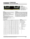
PROGRAMMABLE APPLIANCE
CONTROLLER
[75] Inventors: David L. Beckedorff, Wellesley;
Michael Sporer, Harvard, both of
Mass.; Bruce R. Watts, Portsmouth,
R.I.
3,819,906
6/1974
Gould, Jr. ...................... .. 364/104 X
4,061,927
4,071,745
4,081,754
12/1977
l/l978
3/1978
Link ..................................... .. 307/41
Hall ................................ .. 364/120 X
Jackson .............................. .. 325/396
Primary Examiner-—Joseph F. Ruggiero
[57]
ABSTRACT
[73] A ssignee: Massachusetts Microcomputers, Inc.,
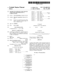
Programmable apparatus for providing random on/off
Wellesley, Mass.
[21] App]. No.: 953,558
control of electrical devices such as appliances. Such
control may be programmed for an entire week, with
Oct. 23, 1978
[22] Filed:
[51] Int. Cl.2 ..................... .. G06F 15/20; HOlH 43/00
[52] US. Cl. ............................... .. 364/104; 307/141.4;
340/147 P; 364/120; 340/309.4; 455/231
[58]
Field of Search ............. .. 364/ 104, 107, 120, 400,
[56]
3,440,434
3,774,056
different programming for each day, and with program
ming control over small blocks of time, eg thirty min
utes. Programming is secured by the use of a combina
tion or look and, in addition, the AC line cord of the
electrical device, which receives or does not receive
AC power depending upon the status of the program, is
364/569; 307/39, 41, 141, 141.4; 340/147 P,
147 C, 309.1, 309.4; 328/130, 194, 114, 122;
locked into the apparatus. During operation, the pro
325/396
played; otherwise the time of day is displayed. The
References Cited
U.S. PATENT DOCUMENTS
4/1969
11/1973
Yates et al. ................. .. 307/l4l.4 X
Sample et al. ................. .. 364/104 X
gram in the apparatus may be interrogated and dis
apparatus also includes a look-ahead feature, turning on
an appliance, such as a television set, earlier than pro
grammed in order to provide sufficient warm-up time.
44 Claims, 12 Drawing Figures
US. Patent
Jul. 14, 1981
V Sheet 1 019
4,27%12
US. Patent
Jul. 14, 198-1
Sheet 4 of9
4,279,012
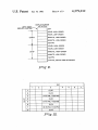
DISPLAY BUFFER
LEFT .. MOST
DISPLAY POSITION
(‘I 2 BYTES)
DAY
HOUR, HIGH-ORDER
HOUR, LOW-ORDER
MINUTE, HIGH-ORDER
MINUTE, LOW-ORDER
AM/ PM
HOUR, HIGH-ORDER
HOUR, LOW-ORDER
MINUTE, HIGH-ORDER
MINUTE, LOW-ORDER
AM/PM
STATUS, DEVICE AND KEYBOARD
Fig’. 6'.
3
2
(0,0)
(0,0)
3
(7=o0 AM, 8=3OAM)
4
(0,0)
5
(300 PM , 4:30 PM)
6
(0,0)
7
(8:30 PM ,11=00 PM)
8
(0,0)
1
Fig‘. 12.
US. Patent
20°
Jul. 14, 1981
Sheet5 of9
4,279,012
ENTER
MAIN CONTROL
LOOP ROUTINE
2o2\
;
EXECUTE TEST ‘BIT MAP
ROUTINE (TBM)
204\
1,
EXECUTE DISPLAY CURRENT
BUFFER ROUTINE-(DOB)
206\
E
EXECUTE TEST FOR NEW
KEYBOARD INPUT
ROUTINE (m)
~ YES
/m
EXECUTE APPROPRIATE
Y
P ROCESSING
IS
THERE A KEY
RESSPH THF‘E-OFOMFTN
m LAY AG; EE
BLINK INDICATOR; SET
TIME-OUT COUNTER = so
IS
COMBINATION
EXPECTED FLAG
$§T
US. Patent
Jul. 14, 1981
4,279,012
Sheet 6 of 9
CONVERT CURRENT TIIIE
OF-OAY (TOD) TO
APPROPRIATE BIT IN
BIT MAP (ON)
I
ADDRESS THE APPROPRIATE
BIT SO DETERMINED
/
I
240
TURN ON DEVICEIS)
STORE CURRENT TOD
‘
/244
INCRENENT STORED
CURRENT TOD BY 30 SEC
/246
CONVERT THE STORED
TOD AS INCREIIENTED TO
APPROPRIATE BIT IN BII
AND ADDRESS BII
Fig‘. 8.
U.S. Patent
Jul. 14, 1981
Sheet 7 0E9
250
ENTER DCB
/252
SET BYTE COUNT = 1
GET NEXT BYTE (BYTE courm /'25‘4
FROM DISPLAY BUFFER
(HIGH ORDER)
BIT;0
N0 /258~
USE LOW-ORDER 6 BITS T0
SELECT A DISPLAY VALUE
/ 260
SEND SELECTED VALUE T0
DISPLAY FOR 30 Pm
INCREMENT BYTE coum
IS
BYTE COUNT * 13
{2
YES
ENTER MCL
’262
4,279,012
U.S. Patent
Jul. 14, 1981
Sheet80f9
.
4,279,012
/-274
SET OOLUNN COUNT * ‘l
276
ACTIVATE NEXHCOLUMN /
couuTY cowuu
/
280
INCRENENT OOLUNN
COUNT
IS ,
CONVERT counm COUNT /284
COLUMN couKT-1s
?
AND ROW ENABLE TO INT.
KEY VALUE
‘
/
DETERMINE CURRENT
KEYBOARD STATE
"MP
‘
K
285
KEY UP ONCE
,
YES
296'
KEY D0"
K
KEY DO" WE
LELNL‘R'S'ESN’NENT
[286
SET STATE T0 KEY ooYm
‘
KEY“
*
P
0m
KEY
UP
0m
K
272\
KEY noYm ONCE
SAVE KEY VALUE FOR
LATER USE
294\
/
KEY 9°“
s m T TO Y
D5" ‘E “E
297\
RETURN To "CL
sET STATE
To KEY UP
ONCE
sET KEY-TO-BE
PROCESSED FLAG
292
T
‘~—----'
V
Fig. 10.
(29a
sET STATE
To KEY UP
US. Patent
Jul. 14, 1981
4,279,012
Sheet 9 of 9
I
ENTER
INTERRUPT ROUTINE
30D
DECR. 60 SEC.TIME-0UT
CTR.
INIT. CTR. T0 60(1 SEC)
304
60SEC. T-O CTR.
=0
IS TDD IN
DISPLAY FLAG=I
?
YES
SET TDD IN DISPLAY
FLAG = I
\5I2
BUFFER
314
BLINK IND. = I
s1s\
?
SET BLINK mn.=o
520
{516
SET BLINK mo. - 1
i
\ I
SET SECONDS TOSEC$.+1
. /
52s
YES
SET AN/PM = PM
SET SECONDS =0
1, /528
$121 mums T0
MINS.+1
____I
346\
SET AM/PM = M4
330
348\ ‘
SET DAY TD DAY +1
RETURN TO SUSPENDED
SEQUENCE
N0 /552
SET MINUTES =0
I /a54
SET HOURS TD HOURS +1
Fig. 11.:
SET DAY TO I
4,279,012
1.
2
PROGRAMMABLE APPLIANCE CONTROLLER
addition, the steps required to program the controller
should be as simple and straight-forward as possible.
BACKGROUND‘OF THE INVENTION
invention to provide a programmable appliance con
It is accordingly the primary object of the present
troller which is convenient and easy to use.
The present invention generally relates to controller
devices and more particularly to'a programmable con-v
SUMMARY OF THE INVENTION
troller for electrical devices such as appliances.
Controllers for electrical devices such as appliances
‘ The objects of the present invention are achieved by
have in one of their simplest 'forms included timers
providing controller apparatus for controlling the oper
which plug into the‘ AC line power source, with the
appliance; such as a light, radio, coffee pot, etc., plug
ation of a device, which apparatus includes a switch,
which switch includes a control input, a source input
and a source output. First and second apparatus for
respectively coupling the source output to the device
ging into the timer. The timer includes a motor which
causes a 24-hour dial to rotate, making one full revolu
tion per day, turning the appliance on and then off once
per day. More recently, such timers have been provided
and the source input to an energy source are also pro
with either a turn on or turn off capability once per
signal, the presence of which enables the coupling of
hour. So-called clock-radios have also been provided
with this turn on/turn off capability integrated therein.
the energy source from the source input to the source
vided. The control input is coupled to receive a control
output. Apparatus for generating the control signal is
also provided and includes apparatus for providing the
current time of day, storage apparatus for storing infor
More sophisticated appliance controllers than the
above-noted timers have also'been developed in the
past. One such controller is described in U.S. Pat. No.
3,577,004. This controller or programmed clock timer is
provided with ‘the capability to operate an alarm and an
appliance on an adjustable 24-hour sequence which is
supplemented with selectively programmed 24-hour
and 7-day timing sequences. In such manner, one or
more appliances may be operated according to a prede
termined program, which is visibly presented on a con
trol panel with individual incremental time segments
being programmed by an array of manually operated
push-pull switches.
Controllers of varying complexity and speci?c uses
may also be seen from U.S. Pat. Nos. 3,965,366;
mation indicative of at least one period of time during
which the control signal is to be generated and appara
tus, responsive to the current time of day and the infor
25
mation stored in the storage apparatus, for enabling the
generation of the control signal.
BRIEF DESCRIPTION OF THE DRAWINGS
For a full understanding of the nature and objectives
of the present invention, reference should be had to the
following detailed description, taken in connection with
the accompanying drawings, in which:
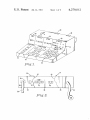
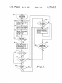
FIG. 1 is a perspective view of the controller of the
present invention;
3,840,752 and 4,035,661,. In addition, other controllers
FIG. 2 is a view of the back panel and cover of the
which have appeared in various newspaper or magazine
controller
of the present invention;
articles for use with, for example, television sets, which
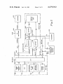
FIG. 3 is a logic block diagram of the controller of
controllers are not necessarily included‘in the “prior”
the present invention;
art, include a programmable television set offered by
FIG. 4 illustrates the manner in which program infor
Heathkit Corporation, a programmabletelevision set
mation
is stored for use in controlling the operation of
which will apparently be offered in the near future by 40
the apparatus of the present invention;
Sharp Corporation, and a television controller which
FIG. 5 illustrates the time of day buffer used in the
will apparently be marketed under the trade name,
controller of the present invention;
Video Proctor, which was the subject of an article in
FIG. 6 illustrates the display buffer used in the con
the Jan. 20, 1978 issue of New York Tribune newspaper
(also see the Mar. 1978 issue of Consumer Electronics 45 troller of the present invention;
magazine).
.
-
Some of the above-mentioned controllers have been
developed, as has the apparatus of the present inven
tion, based on the rising concern about the quality of
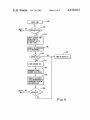
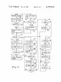
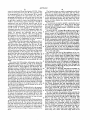
FIG. 7 is a flow diagram of the ?rmware for the main
control loop routine of the controller of the present
invention;
television programming, TV violence, and increasing
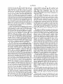
FIG. 8 is a flow diagram of the ?rmware for the test
bit map routine of the controller of the present inven
concern about TV addiction among children; Thus, a
tion;
convenient, low-cost way to regulate the amount and
type of TV programs would help to alleviate such con
display current buffer routine of the controller of the
cerns. In addition to the use of such controller for regu
present invention;
lating televisionusage, it is also important to control
other electrical devices such as common household
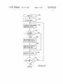
FIG. 10 is a flow diagram of the ?rmware for the test
for new keyboard input routine of the controller of the
appliances, including lights, radio, toaster, tape record
present invention;
ers, video tape recorders, etc. Additionally, such con
troller should have the capability to turn such appliance
on and off at completely random times for use, for ex
ample, as a security timer.
For many of the above-noted applications, the con
troller must be able to be locked, i.e., the programming
of the on/ off sequences should not be alterable without
a key or combination under the control of an authorized
operator. Further, for convenience, the controller
should be useable without the need for the services of,
for example, a TV repairman to install the controller. In
FIG. 9 is a flow diagram of the ?rmware for the
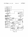
FIG. 11 is a flow diagram of the firmware of the
interrupt routine of the controller of the present inven
tion; and
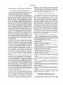
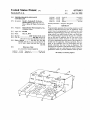
FIG. 12 is an alternative manner for storing program
information for use in controlling the operation of the
apparatus of the present invention.
DETAILED DESCRIPTION OF THE
PREFERRED EMBODIMENT(S)
The programmable appliance controller of the pres
ent invention is shown in FIGS. 1 and 2. FIG. 1 illus
4,279,012
3
trates the keyboard 10 and the display 12. FIG.42 illus
4
The function keys are used in conjunction with the
trates the back panel and cover 14. The controller may
data keys to specify days, start times, and stop times.
be programmed by use of the keyboard 10 to control
They are also used to store and review time ranges, to
one or more appliances for a full week cycle. The pro
set and display the controller’s clock (time of day), and
gramming information, as well as the time of day, may
be displayed on display 12. As will be seen, the control
to clear memory and errors. The ten keys which may be
used in the function section are: day, start, stop, store,
ler provides a means to control each half-hour interval
review, set time, display time, clear memory, clear day,
within a one-week time period, although it should be
understood that such half-hour interval may be de
creased (or increased) by use of more (or less) memory
and clear error.
storage as shall be discussed. The controller thus allows
on/off control of such appliances as television sets,
videotape recorders, radios, hi-? equipment, lights, etc.
automatically by use of a program preset into the con
troller. As desired, the controller may be repro
grammed at any time. Further, after the program has
been entered, the controller, i.e., the keyboard 10 (i.e.,
the ability to enter programs using the keyboard) may
be locked by use of a combination so that no unautho
The data keys are used to specify a particular day of
the week of a particular time. Keys used in this ?eld
may include: l/MON (i.e., l or Monday), 2/TUE,
3/WED, 4/THU, S/FRI, 6/SAT, 7/SUN, 8, 9, 0, full
colon, AM and PM.
As shown in FIG. 1, hinges 38 and 40 are used, and as
shown in FIG. 2, such hinges are used (only hinge 38 is
shown because of the breakaway 42 and 43) to hold a
lockable back cover 44 which, by use of a key lock 47,
serves to lock the back cover 44 over that portion of
backplate 46 which includes AC power sockets 48 and
20 50 and combination (code) switches 52. The controller
rized changes may be made to the program.
of the present invention is used to control the availabil
The display 12 of the controller as shown in FIG. 1
ity of power to the sockets 48 and 50 to which an appli
includes a time ?eld 16 and a status ?eld 18. The time
ance may be connected. As shown, up to two appliances
?eld 16 includes three sub?elds: day 20, start 22 and
may be controlled at the same time; however, it should
stop 24. The day ?eld 20 indicates the day of the week
while the start and stop ?elds indicate the time an appli
ance will be on. The AM/PM designation is provided
with each start and stop time. These start and stop times
change depending on the program. For example, in a
given day there may be several start and stop times. As
shall be seen, the controller also displays the time of
day. The day of week and time of day'are displayed in
respectively the day sub?eld 20 and the start sub?eld
be understood that by the use of additional sockets,
additional appliances may be controlled. The controller
receives its AC power via line cord 54 which is plugged
into an AC wall outlet.
As stated, the line cord of the appliance to be con
trolled is, with back cover 44 unlocked and moved out
of the way by rotation about its hinged edge, plugged
into one of the sockets which is itself recessed, or with
the backplate, or portion thereof, is recessed to accom
22, and when so displayed, the stop sub?eld 24 is left
modate the size of the appliance’s line plug, thereby
blank.
35 allowing the back cover to beplaced in its proper-posi
The status ?eld 18 includes information about the
tion and locked. In doing so, only the line cord 56 of the
appliance(s) being controlled as well as the keyboard.
appliance remains outside the back cover through the
The status is indicated by use of the display for sub?elds
accommodating slot 58, with the plug of such line cord
26, 28 and 30 for both appliance and keyboard. For
56 secured into the socket 50.
appliance status, if sub?eld 26 is lit, this means that it is
Also included on the back plate 46 and lockable by
operable and under program control; if sub?eld 28 is lit,
back cover 44, is a switch 52, which may, by way of
this means that the appliance is not operable (because
example, include four positions. The authorized opera
the program calls for it to be off), but is under program
tor of the controller (usually a parent when the control
control; and if sub?eld 30 is lit, this means normal oper
ler is used to regulate the children's television viewing)
ation with no program control. If the on/off control of 45 sets a four digit secret code which will be inaccessible
the appliance is in the on position, the appliance will
actually switch on and off according to the program in
the controller. If the on/off control is in the off position,
only sub?elds 26 and 28 in the status ?eld 18 will switch
on and off according to the program; however, when
?eld 26 is lit, the appliance may be turned on by use of
and hidden from view- (i.e., locked) when the back
cover 44 is secured in place. Thus, the operator must
remember this number to unlock the keyboard to enter
a program, which unlocking is done simply by pressing
the Unlock Keyboard key and depressing the secret
code or combination. Of course, if the operator forgets
the code, he need simply unlock the back cover 44 and
For keyboard status, if sub?eld 26 is lit, this means it
look at the switch 52. The code set in by switch 52
is unlocked and that data can be entered; if sub?eld 28 is
(code 7825 is shown in FIG. 2) may be reset at any time,
lit, this means the keyboard is locked and that the com 55 for example, if the children break the code.
the on/off control thereof.
'
bination or code must be entered by use of the keyboard
By way of example, the operation of the controller by
to unlock the keyboard; and if sub?eld 30 is lit, this
means that a keyboard error has been made. The total
an operator shall now be discussed. Suppose the opera
tor desires that his television set be operable each week
number of display positions may thus, by way of exam
day between the hours of 7:00 A.M.- to 8:00 A.M., 6:00
ple, include twelve display positions.
The keyboard 10 is shown to include three sections or
groups of keys: the control keys 32, the function keys
34, and the data keys 36. The control keys are used to
lock and unlock the keyboard 10, and to begin and end
program control. The keys which may be used, some of
which will be referred to hereinafter, are: Unlock Key
RM. to 7:30 P.M., and 9:00 RM. to 11:30 RM. The
operator ?rst insures that the controller is no longer
under program control. This is done by pressing the
End Program key, following which the controller’s
memory storage is cleared by use of the Clear Memory
key. The following sequence of keystrokes is then en
tered: Start, 7:00 A.M., Stop, 8:00 A.M., Day, Mon.,
board, Lock Keyboard, Begin Program and End Pro
Store, Day, Tue., Store, Day, Wed, Store, Day, Thu.,
gram.
Store, Day, Fri., Store. The time range need not be
5
4,279,012
reentered for each day since the Store key does not
erase the information already keyed infThe next time
range (6:00 PM. to 7:30 P.M.) is entered in a similar
fashion (the only change from the above sequence is
that 7:00 A.M. is replaced by 6:00 RM. and 8:00 A.M.
by 7:30 FM). The next time range is programmed in
6
noted as P23-27, with one line, P27, coupled to the
control input of switch(es) 104 and with four lines
(P23-P26) coupled with converter 162. Lines 144 in~
clude eight lines (DEG-DB7) with four lines
(DBO-DB3) received from keyboard 108 and the other
four lines (DB4-DB7) received from combination en
exactly the same manner. Once all ranges have been
tering device 110.
entered, the appliance may be placed under program
control by use of the Begin Program key. It should be
nism’s, for example, a solid state relay, triac or micro
The AC switch 104 includes one or more mecha
understood that there is virtually no limit to the number
switch which will control one or more devices requir
of program ranges in each day, the only limitation being
dictated by the length of the programmable intervals,
e.g., thirty minutes. Thus the controller could be, by
ing line power. The control line 142 coupled to control
troller includes ?ve major units: the microprocessing
vices.
The display unit 106 has two primary functions, both
of which have to do with communicating information
switch 104, enables or disables the connection of the AC
IN line to the AC OUT line, thereby energizing or
way of example, turned on and off every half hour. It
de-energizing the connected devices 102. One switch
should also be understood that the time ranges may be 5 would be used for each of the devices 102 with control
different for each day. For example, on weekends, a
line 142 being used, in parallel, to control each such
time range during the afternoon may be programmed
switch. However, it should be understood that only one
for viewing of sports programs.
such switch need be used independent of the number of
A logic block diagram of the apparatus of the present
devices 102 connected for control so long as such
invention is shown in FIG. 3. Such apparatus or con
switch can handle the power requirements of the de
unit (MPU) 100, a device control unit, or AC switch
104, the display 106, the keyboard 108 and the combina
tion entering device 110. Such apparatus is coupled to
control one or more appliances or devices 102. The 25
from the MPU 100 to the operator. The display 106 may
include several display devices (DD) 160. Devices 160
apparatus would also include a power supply, not
may, by way of example, be light emitting diodes
shown, for providing the necessary power to such units.
(LEDs), several for each position of display, which
As shown, the AC switch 104 is coupled to receive the
positions are organized in a multiplexed display con?g
AC line input (AC IN) directly and the MPU 100 is
uration. This means that each display position of which
coupled to receive a 60 Hertz (cycle) signal which may
there are, for example and as has been seen, twelve,
be derived from the AC line input frequency. Where 60
requires two pieces of information in order for the
Hertz is not the AC line frequency (for example, it may
LEDs at each position to be illuminated. The MPU 100
be 50 Hertz), a frequency conversion is required. Each
provides these two pieces of information in a rotating
such unit and its function shall now be described.
manner so that ?rst one position is activated, then the
The MPU 100 may be, for example, that micro 35 next, and so forth until all have been activated. The
processor electronic chip model number 8049 manufac
rotation then commences anew with the ?rst position.
tured by Intel Corporation and described in Intel publi
The ?rst piece of information identi?es the position to
cation document number 98-27OC, dated January, 1978,
be activated (when one position is activated, all others
and entitled “MCS-48 Family of Single Chip Mi
are dormant and will not be energized; however, the
crocomputers User’s Manual.” The MPU includes ?ve 40 display appears continuous to the human eye due to the
major functions including: a control store 132, a data
integration properties of the eye which allows a person
memory 134, an arithmetic computation unit (ACU)
to view, for example, television images as continuous
136, a timing and control unit 138, and an input/output
images while in reality there are discrete frames being
unit (I/O) 130. The MPU 100 executes sequences of
displayed). The second identi?es which of eight possi
control ?rmware instructions. The particular sequence 45 ble LED’s in a given position are to be illuminated.
thereof is determined by the MPU based on information
The eight possible LEDs are set in a physical orienta
obtained from the other units. The MPU affects the
tion such that three horizontal bars and four vertical
other units by transmitting information to them based
bars can be used to display alphanumeric information
on the particular control ?rmware instructions. The
with the eighth position being the decimal point which
MPU has an internal cycle time (the time to perform the
is not needed for the display of the controller of the
function speci?ed by a control ?rmware instruction).
present invention. Actually, and with brief reference to
An external circuit, not shown, but consisting of an
inductor and 2 capacitors, is used in conjunction with
circuits within the MPU to determine the internal cycle
FIG. 6, only the hour and minute positions (a total of 8)
use up to eight possible LEDs. The other positions, for
example AM/ PM are LEDs which have either AM or
time. In addition, the MPU keeps track of the time of 55 PM lit. The same is true for the day ?eld, i.e., either
day in much the same way as an electronic digital clock.
As such, a signal on line 150 is provided which is de
MON or TUE or WED, etc. is lit. The status ?eld may
include 6 LEDs or simply six light bulbs, one for each
rived from the AC line signal. This signal is cyclic,
repeating its pattern 60 times per second. The MPU
keeps track of the time of day by counting occurrences
of this signal. After a count of 60 is reached, the mi
crocomputer senses that 1 second of time has elapsed.
The MPU 100 exchanges information with the other
components over lines 140, 142, and 144. The MPU
sends information to the units using lines 140 and 142
The MPU applies the position identi?er on line 142.
Ths is processed by converter 162 and buffer 164 and
then sent to the display device 160. Buffer 64 provides
electrical buffering to insure that the display has the
proper current and voltage to illuminate the speci?ed
LEDs.
and receives information from units 108 and 110 using
encoding scheme to another. The ?rst scheme, called
lines 144. Lines 140 include eight lines P10—P17. Lines
142 include ?ve of eight possible lines. The ?ve lines are
position.
Converter 162 converts the information from one
binary-coded, is used by the MPU so as to minimize the
interconnections between units 100 and 106. in this
4,279,012
8
The combination entering device 110 is used to estab
encoding, any number between 0 and 15 can be repre
sented using the four signal lines (P23~26) of line 142.
lish the key or “combination” (lock information) which
must be entered by the operator at the keyboard 108
prior to the commencement of the programming of the
apparatus of the present invention by an operator. This
Converter 162 converts this to a linear-coding scheme
wherein only one of the 16 lines (CKEO-CKEIS), (only
12 lines (CKE4—CKE15) are received by buffer 164 and
keyboard 108) of lines 145, which wire corresponds to
the number specified by the MPU is activated. For
example, suppose that the MPU wants to illuminate
LED position 7. The binary-coded version of this, 01 l 1,
combination or look is designed to be secure to prevent
unauthorized use of the apparatus of the present inven
tion. Device 110 may include several switches, such as,
but not limited to, so-called thumbwheel switches or,
is presented on line 142. Converter 162 converts this so
for example, microswitches manufactured by Eeco Cor
that the appropriate line of lines 145 is activated. When
poration. The characteristics of device 110 are similar to
those of keyboard 108. Thus the MPU scans each of the
buffered by buffer 164, this will permit LED’s at posi
tion 7 to be activated. The second piece of information,
plurality of switches included in device 110 by use of
which of the eight available LED’s at a given display
position are to be illuminated, is provided by the MPU
lines CKEO-CKEIS and senses the position of the cor
responding switch on lines DB4-DB7.
The data memory is contained within the MPU. It is
used to store information which the MPU will need at a
on line 140. This is buffered by buffer 166 and sent to the
display device 160. The MPU holds the information on
lines 140 for a period of time. This time is suf?cient to
later time. The data memory, by way of example, is
insure that the individual LED’s will be illuminated and
comprised of 128 bytes of storage. A byte is composed
seen by the operator. The buffers 164 and 166 may be 20 of 8 binary digits (bits) and can be used to hold a number
which ranges from 0 to 255. Also, a byte may be
those manufacture by Texas Instruments, Inc. having
part numbers 7407 and 75491 respectively, whereas
thought of as containing a pattern of 8 bits which are
converter 162 may include that device having part num
not interpreted to represent a number. As an example,
ber 74154.
the time-of-day buffer (described hereinafter) will con
As mentioned above, the MPU uses the display to 25 tain the binary pattern 00001010 to indicate that the
communicate two types of information to the operator.
time lies between 12:00 Midnight and 12:00 Noon. The
major sections which hold different types of informa
In the ?rst mode, the operator is entering the program
tion will now be described.
ming information into the apparatus of the present in
vention with the intention of establishing a schedule for
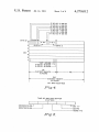
The Bit Map, shown in FIG. 4, is a data buffer which,
automatic operation of the connected device(s). This 30 by way of illustration for one embodiment, includes 42
mode is also used to review the programming informa
bytes. The information that it contains is interpreted as
tion previously entered into the invention. In this pro
the control program for the connected devices. Thus
gramming mode of operation, the display will show the
day of the week, the time that the controlled device(s)
when the operator enters a program for the control of
instructed to do so by the operator, or in any case 60
contain numeric information. It is considered to contain
a sequence of 1’s, each of which occupies one bit posi
tion. Each bit will indicate that the connected devices
the connected devices, the MPU will sequence through
is to be turned on, and the time that it is to be turned off. 35 the control ?rmware and change the values of one or
The MPU has an internal table, hereinafter referred to
more bytes within the Bit Map. During normal running,
as the Bit-Map, which is included in its internal data
the MPU will use the current time-of-day to identify a
memory 134 which determines‘ when the controlled
portion of the Bit Map that is to be examined. The Bit
devices are to be activated or turned off. The second
Map will contain a datum at the examined portion
piece of information will be displayed when the inven 40 which will indicate whether the connected devices are
tion is not being programmed. It will commence when
to be turned on or off. The lBit Map is not considered to
seconds after the last command given by the operator.
In this second mode of operation, the current day of the
45 are to be turned on or off for a given 30-minute period.
week and the current time will be displayed.
The keyboard 108 is used to enter programming in
For example, if the connected device is to be turned on
formation into the apparatus of the present invention. It
at 12:00 A.M. on Monday, then the bit which represents
is also used to set the proper day of the week and cur
this time period will be set to a one when the controller
is programmed. When the time-of-day reaches 12:00
rent time. The keyboard may, by way of example, be a
matrixatype keyboard with, for example, forty-eight
50 A.M. on Monday, the MPU will examine the corre
positions. However, for purposes of the present inven
tion, only some of these keys are actually used and, in
fact, the key positions which are not used, may not have
actual keys (see FIG. 1)‘or such keys may not be made
accessible to the operator. With such matrix-type key 55
sponding bit. Upon ?nding the bit a 1, the MPU will
instruct the proper circuitry to turn the connected de
vice on. For the example given (12:00 A.M. on Mon
day), the bit which represents this time period is the
eighth bit of byte 0 in the Bit Map.
board, it may include twelve columns and four rows.
The manner in which the byte and bit to be examined
When a key is depressed, a connection is established
are found is discussed hereinafter. However, as can be
between the column and the row under the key. The
seen from FIG. 4, there are 7 days represented with day
MPU l0 periodically scans the keyboard and senses
1 being Monday and with the 24 hours in each day
when a key is depressed. The MPU activates each of the 60 represented by 6 bytes (48 bits). If the ?rst byte in day
twelve columns and senses ‘the four rows at each activa
1 is designated as byte 0, then 11:30 A.M. on Sunday
tion. When a key is depressed, the keyboard will trans
(day 7), is the ?rst bit of byte 38 (the 39th byte). Thus,
fer the activation signal from the active column to the
as can be seen for day l, the last bit of each byte repre
connected row. Thus‘the MPU will sense which key
sents the ?rst thirty minutes of the four~hour time frame
has been depressed. The MPU will activate each of the 65 of the byte, etc, with the ?rst bit representing the last
twelve columns by using the converter 1.62 described
thirty minutes of such time frame. This is done to sim
hereinabove. It will activate each line CKE4-CKE15
plify the calculation for the bit which is to be examined
while it senses the rows on lines DEG-DB3.
as discussed hereinafter. It should be understood that
4,279,012
the Bit-Map may have included more than 42 bytes. For
example, to one extreme, each bit could have been set to
designate a one-minute (or even one-second) time inter
val. For example, if each bit were allowed to represent
?fteen minutes (rather than‘ thirty minutes as discussed
above), then the Bit-Map would have included 84 bytes
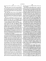
10
executed. If there is no key depressed and thus no key
board input to be processed then as indicated by test
block 208, TBM 202 is again entered. Otherwise, after
the housekeeping functions indicated in block 210 are
processed, block 212 is entered. If the keyboard is un
locked and there is no error condition, the key that was
.
depressed is processed by the appropriate keyboard
i‘ The Time-of-Day buffer shown in FIG. 5 includes 5
bytes which hold the current time. The time is set under
control of the operator. Once the operator has set the
processing routine as shown in block 220. If there is an
rather than 42 bytes.
time, it will be entered into the Time-of-Day buffer.
error condition, as indicated by block 212, only an input
from the Clear Error key is accepted as shown in block
214. Otherwise, the TBM 202 is again executed. A de
Each time the MPU senses that one second of time has
termination is made as indicated by block 216 as to
elapsed, the time if brought up to date. The ?rst byte
whether the keyboard is locked. Block 216 is entered by
will contain a number which is interpreted to represent
either a YES answer from block 214 or a NO answer
seconds (00 to 59). The next byte will contain the min
utes indicator (00 to 59). The third will contain the
hours (1 to 12). The fourth contains a speci?ed bit pat
propriate keyboard processing routine is executed
tern (00001010) if the current time is A.M. while it
contains another pattern (00001011) if the current time
tered and a determination is made as to whether unlock
from block 212. If the keyboard is not locked, the ap
(block 220). If the keyboard is locked, block 218 is en
keyboard is the key input. If not, block 219 is entered
is RM. The ?nal byte holds the day where 1 represents 20 and a determination is made as to whether the combina
Monday, 2 represents Tuesday, and so on until 7 repre
tion expected flag is set. If NO, then block 202 is again
sents Sunday.
entered. If YES from block 219 or from block 218, then
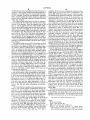
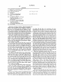
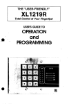
The display buffer shown in FIG. 6 includes, by way
the appropriate keyboard processing routine is executed
of example, 12 bytes of storage, one for each item of
as indicated by block 220. After executing the appropri
information to be displayed. Each byte contains a num 25 ate keyboard processing routine, the MCL is again pro
ber which is used as a pointer into a conversion table
which is included in the control store. This table con
tains a bit pattern at each entry which indicates which
cessed by beginning the execution of block 202.
A flow diagram of the Test Bit Map routine (TBM) is
shown in FIG. 8. The TBM causes the Bit-Map (BM) to
be examined once per cycle of the MCL. After TBM is
illuminate the corresponding entry. For example, the 30 entered (block 230), a determination is made as to
conversion table contains a binary 11111110 in the entry
whether the program flag is on (block 232). The pro
that indicates that the number 8 has the ?rst 7 segments
gram flag is turned on and off by respective keys there
segments of each display position are to be activated to
(but not the decimal point) illuminated. Each of the
values in the display buffer will be examined when the
display is being activated and used to obtain the corre
sponding conversion table entry. The high-order bit
for included in the keyboard. If the program ?ag is off,
the MCL is again entered. If the program flag is on, the
current time of day (TOD) is converted to the appropri
ate bit in the Bit-Map (BM) and such bit is addressed as
(left-most) of a display buffer entry is set to a 1 to indi
indicated in blocks 234 and 236. The manner in which
cate that the low-order (right-most), by way of exam
such conversion takes place is explained elsewhere
pie, 6 bits contain a valid entry to be displayed. This is
herein. If the bit addressed is a binary one, the devices
useful to distinguish a blank display entry from one 40 are turned on as indicated by block 240. If, on the other
containing the number 0.
hand, the answer from decision block 238 is NO, the
The display buffer is shown to include a left-most and
current TOD is stored in a temporary location of the
a right-most position which corresponds to their physi
cal position on the front display panel as shown in FIG.
local memory (block 242) and the value of the current
TOD is incremented by thirty (30) seconds thereby
1. Both the start and stop information are shown. Com 45 looking ahead to see if a device should be turned on a
mon to both are the hour-high order and low order
little early (for example, thirty seconds) to allow a de
information, e.g., for 12 o’clock, hour-high order is 1
vice such as a television set to warm up. Following the
and hour-low order is 2. The same is true for the mi
step of so converting and addressing as indicated by
nute~high order and low order information. A.M. or
block 246, if this new bit, which is representative of
PM. is also displayed for both the start and stop infor
mation. The day and status information are also dis
played.
The remaining data locations of the data memory are
used to store various pieces of information during the
operation of the controller of the present invention.
Such information includes ?ags, tables and other infor
mation which are used during the operation of the pres
ent invention. The description of the various ?rmware
sequences will expand on the use of such information.
such thirty-second increment from the current TOD; is
a binary zero, the MCL is again entered (block 248).
Otherwise, if a binary one, the device(s) is turned on
(block 240).
The following description will show how the current
time of day is converted to point to the appropriate bit
in the Bit-Map (see block 234 of FIG. 8) by use of the
arithmetic unit in the MPU. The appropriate byte in the
Bit-Map is determined by use of the following formula:
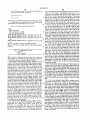
The Main Control Loop routine (MCL) is shown by 60
the flow diagram of FIG. 7. The MCL is executed
repeatedly. It directs the execution of other various
where:
routines and is analogous to a traf?c director. The MCL
BP is byte pointer;
is entered at block 200, following which the Execute
Test Bit Map routine (TBM) 202 (see FIG. 8) is exe 65
cuted; the Display Current Buffer routine (DCB) 204
(see FIG. 9) is executed; and then’ the Test for New
DAY is the current day;
PM is 1 if current time is PM; and
MOD is the modulus function, i.e., MOD (hour,
Keyboard Input routine (TKI) 2.06 (see FIG. 10) is
12)/4 means use 0 if hour is 12, otherwise use the
hour and then integer divide by 4. By way of exam
11
4,279,012
ple, the byte in which 11:30 A.M. of the 7th day is
12
key is currently down. This routine will convert the key
located is determined as follows:
value into an internal representation and save it in a
temporary byte (block 272). This routine will perform
the function of de-bouncing the input keys. This means
that no processing will proceed until the key can be
guaranteed to be down. This is accomplished by main
The answer is byte 38 (assuming the ?rst byte is byte 0).
To determine the particular bit in the byte above
determined, the following formula is used:
taining a status indicator which de?nes the current state
of the keyboard. The 4 states that a key may be in are:
10
BM=M.LS. (MOD (MOD (HOUR, l2), 4) ‘2)
Key Up means that all of the keys are currently up
and that the keyboard is in its neutral position. Key
Down Once means that this is the ?rst time through this
where:
routine that we detected a key down. This state is en
BM=Bit Mask;
tered from the Key Up state when a key is sensed as
down. In addition to the state transition, the value (in
ternal representation) is saved in a temporary data byte.
This state is also maintained when a key is sensed down
which has a different value than the one saved previ
M=1 if minute is 0-29;
M=2 if minute is 30-59;
MOD (MOD (HOUR, 12), 4)=0 if Hour=4, 8 or 12,
MOD (MOD (HOUR, 12), 4):1 if Hourzl, 5 or 9,
MOD (MOD (HOUR, 12), 4)=2 if Hour=2, 6, or 10,
and
Key Up, Key Down Once, Key Down, Key Up Once.
‘
20
MOD (MOD (HOUR, 12), 4)=3 if Hour=3, 7, or 11;
ously. The new key value replaces the previous one and
the state is maintained as Key Down Once. Key Down
means that the routine has sensed the same key down
for two invocations and thus is prepared to process the
and
M.L.S.=left shift of M by the MOD number
key. This state is entered from the Key Down Once
Thus, by the above example, BM would be calculated as
state
when a key is sensed as down which has the same
follows:
25
value as that saved in the temporary data byte. This
state is left when this routine senses no key currently
BM - 2.LS. (MOD(MOD(ll,l2),4)*2
depressed. Key Up Once means that we were in the
2.LS. (3*2)
Key Down state and no key depressed was detected.
2.LS. 6
When this routine ?nds no key depressed in the Key Up
binary 10000000
Once state, the Key Up state is entered. The TKI rou
tine will cause a key processing routine to be dispatched
Thus, the bit is indicated by the binary one which by
when the Key Down state is entered. The value of the
this example is in the left most position. This correlates
depressed key is passed to the Main Control Loop rou
with the bits shown in the Bit-Map of FIG. 4.
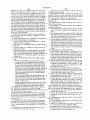
The Display Current Buffer routine (DCB) as shown 35 tine‘(MCL) so that it may invoke the proper keyboard
processing routine.
in FIG. 9 is entered at block 250. This routine is used to
'
I
More particularly, after entering the TKI routine, the
display the contents of the display buffer shown in FIG.
6. Each byte of the display buffer is examined. If the
high order bit is a binary zero, the current byte will not
be displayed and the routine will proceed to the next
byte. If the high-order bit is a binary one, the low-order
six bits specify the information that is to be displayed.
column count is set equal to one (block 274) following
which the column (next column) indicated by the col
umn count is activated (block 276). The question is then
asked (block 278) as to whether any row is enabled by
the depression of an appropriate key on the keyboard. If
the answer is NO, then the column count is incremented
(block 280) following which a determination is made as
table which is stored in the control store. Such value
represents the segments of the display position to be 45 to whether or not all twelve columns have been acti
These six bits are used to obtain a value in a conversion
vated (block 282) and, if. not, reentry is made to block
illuminated. Thus, after initially setting the byte count
to equal one (block 252), such byte indicated by the byte
276.
count is fetched (block 254) and as shown by block 256,
either the byte count is incremented (block 262) or the
conversion is made of the column count and the row
If a row was enabled, block 284 is entered and a
low order six bits of such byte are used to select a dis 50 enabled to an internal key value. A determination is
play value (block 258). Such value is used for the dis
then made as to the current keyboard state (block 285).
play to the operator for a short period of time. After
incrementing the byte count, a determination is made to
see if all twelve bytes have been examined and dis
If it is Key Up, the Key Down Once state is set (block
286). If Key Down Once, then a determination is made
as to whether the current key is equal to the previously
saved key value (block 288), and if not, block 272 is
entered. If equal, then the Key Down state is set (block
290) following which a key-to-be-processed flag is set
played as appropriate. Thus, if the byte count equals
thirteen (block 264), then all such bytes have been so
scanned and the MCL is again entered. If not all bytes
have been so scanned, block 254 is again entered and the
display information in the next byte is displayed as ap
propriate. The process continues until all bytes have
been displayed as appropriate.
The Test for New Keyboard Input routine (TKI) is
55
(block 292) for use by the appropriate key processing
routine entered by means of the MCL which is returned
to (block 294). Block 294 is also entered if the state so
determined is Key Down. If the Key Up Once state is
determined by block 285, block 296 is entered and a
shown entered at block 270 of FIG. 10. This routine is
determination is again made as to the current keyboard
responsible for reading the operator input from the
state. If Key Up or Key Down Once, return is made to
keyboard. To accomplish this, this routine will follow 65 the MCL. If Key Down, the Key Up Once state is set
the procedure discussed with respect to the keyboard
(block 297) and return is made to the MCL. If Key Up
hereinafter. This will lead to an identi?cation of the key
Once, the Key Up State is set (block 298) and return is
that is currently being depressed or an indication that no
made to the MCL.
4,279,012
13
The Interrupt routine shown in FIG. 11 is executed
every second. This routine is entered at block 300. Once
the MPU counter has been initialized (block 302), it will
plete and the suspended sequence is resumed (block
324). If the seconds byte has reached 60 seconds, it is
count 60 cycles of the 60 cycle line and then generate an
reset to 0 (block 326) and the minutes byte is incre
mented by 1 (block 328). If the new minutes value is less
than 60 (block 330), a return is made to the suspended
interrupt, once every second. This will cause the MPU
to suspend the sequence that it is currently executing
and temporarily commence executing the interrupt
sequence. When this sequence has completed, the MPU
sequence (block 324). If the minutes byte has reached 60
minutes, it is reset to 0 (block 332) and the hours byte is
incremented by 1 (block 324). If the hours byte is less
will resume the sequence that was suspended. The se
quence that was suspended will not be altered in any
than 12 (block 336), a return is made to the suspended
sequence. If the hours byte is 13 (block 338) it is reset to
1 (block 340) and return is made to the suspended se
quence. If the hours byte is 12 (NO answer from block
way as a result of the interrupt. During the interrupt
sequence, the counter is reinitialized to count another
60 cycles. The time-of-day (T-O-D) in display ?ag is
examined (block 304). If it is a 1, then the current time
of-day is moved into the display buffer (block 306). This
14
value is less than 60 (block 322), the interrupt is com
336 and a NO answer from block 338), then the
15
will insure that the current time is being displayed. If
AM/ PM byte is examined (block 342). If the AM/ PM
byte indicates AM, it is set to PM (block 344) and a
the answer to block 304 is NO, then the controlled
return is made to the suspended sequence. If it indicates
apparatus of the present invention is being used by the
PM, it is set to AM (block 346) and the day byte is
incremented by 1 (block 248). If the day byte is less than
operator and some other information is in the display.
However, the 60 second time-out counter is decre 20 8 (block 350), a return is made to the suspended se
mented (block 308), and if it reaches 0 (block 310), then
quence. If the day byte is 8, it is set to 1 (block 352) and
the time-of-day in display ?ag is changed to a 1 (block
return is made to the suspended sequence.
312) and the time of day is moved into the display buffer
As discussed hereinbefore, appropriate keyboard
(block 306). The ?nal purpose of the Interrupt routine is
processing routines are executed in response to the
to update the time-of-day buffer. In addition, the blink 25 depression of the appropriate keys. Such keyboard pro
indicator is reversed. The blink indicator will cause the
cessing routines are under control of the Main Control
colon between the hours and minutes of the time-of-day
Loop routine (MCL). Each keyboard processing rou
to alternate between illuminated and dark. This alterna
tine will perform its speci?ed function and then returns
tion will take plate at 1 second intervals so that the
control to the MCL. The operation of such keyboard
colon will be lighted for 1 second and then dark for 1
processing routines are shown by the following flow
second (blocks 314, 316, and 318).
The time-of-day buffer is updated in stages. First, the
listings. A description of each of the ?ow listings fol
lows. Keyboard Processing Routines
second byte is incremented by 1 (block 320). If the new
1.
1.1
1.2
1.3
DAY
set DAY in display to 0
set day~expected flag to 1
set review-not-initialized ?ag to 1
1.4
return to MCL
2.
START
2.1
is day-expected = 1?
2.2
2.3
set START field of display to blank
set right-hand digit of hour ?eld to 0
24
2.6
set hour—expected flag to point to right-.
hand digit of START hour
set minute-expected ?ag to point to right
hand digit of START minute
set AM/PM-expected ?ag to point to AM/PM of
2.7
2.8
3.
3.1
return to MCL
set error light and return to MCL
STOP
is day-expected = 1?
3.2
3.3
set STOP ?eld of display to blank
set right-hand digit of hour ?eld to 0
3.4
set hour-expected flag to point to right
hand digit of STOP hour
set minute-expected ?ag to point to right<
hand digit of STOP minute
set AM/PM—expected ?ag to point to AM/PM
of STOP
2.5
yes = 2.8, no = 2.2
START
3.5
36
3.7
3.8
return to MCL
set error light and return to MCL
4.
4.1
42
UNLOCK KEYBOARD
set combination-expected ?ag to 1
set digit-number-expected to 1
43
return to MCL
5.
D1G1T 0-9, MON-SUN.
5.1
5.2
5.3
5.4
is
is
is
is
day~expeeted ?ag = 1?
combination-expected ?ag = 1?
hour-expected ?ag : 0?
minute-expected Flag = 0?
5.5
set error light and return to MCL
5.6
is 1 2 DAY 2 7?
5,7
insert converted DAY into Display
Buffer, reset day-expected ?ag to 0
yes = 3.8, no : 3.2
yes
yes
yes
yes
=
=
=
:
5.6,
5.9,
5.4,
5.5.
no
no
no
no
=
=
:
:
5.2
5.3
5.15
5.17
yes : 5.7, no = 5.5
4,279,012
15
-continued
5.8
return to MCL
read code switch (digit-number-expected)
and compare to new digit
are they the same?
yes = 5.12, no = 5.11
reset combination-expected flag (to 0)
go to 5.5
is digit-number-expected = 4?
yes = 5.14, ‘no = 5.13
increment digit-number-expected
unlock keyboard
go to 5.8
go to 5.8
is right-hand digit in hour ?eld = 0?
yes = 5.16, no = 5.17
set right-hand digit to blank
move right-hand digit to left~hand
go to 5.18
digit position
' insert new digit into right-hand digit
position
go to 5.8
COLON (z)
reset hour-expected ?ag (to O)
is minute-expected ?ag = 0?
'
yes = 6.3
no = 6.4
set error light and return to MCL
set minute ?eld to 00
return to MCL
AM
is AM/PM-expected ?ag set (not 0)?
reset hour-expected ?ag (to 0)
reset minute-expected flag (to 0)
put AM into position speci?ed by AM/PM
expected ?ag
reset AM/PM-expected ?ag (to 0)
yes — 7.2, no = 7.7
return to MCL
set error light and return to MCL
PM
is AM/PM‘expected ?ag set (not 0)?
reset hour-expected ?ag (to 0)
yes = 8.2, no = 8.7
reset minute-expected ?ag (to 0)
put PM into position speci?ed by AM/PM
expected ?ag
reset AM/PM~expeeted ?ag (to 0)
return to MCL
-
set error light and return to MCL
LOCK KEYBOARD
set keyboard locked status into display
reset day-expected flag to O
reset hour-expected ?ag to O
reset minute-expected ?ag to 0
reset AM/PM-expected ?ag to 0
reset combination-expected flag to 0
return to MCL
SET TIME
convert display buffer to time-of-day buffer
return to MCL
DISPLAY TIME
move time-of-day to display buffer
set time-of-day-in~display flag to 1
return to MCL
CLEAR ERROR
turn error light off
return to MCL
BEGIN PROGRAM
set program ?ag to on
return to MCL
END PROGRAM
set program ?ag to off
return to MCL
CLEAR MEMORY
15.1
A
set each of the 42 BIT MAP bytes to 0
return to MCL
CLEAR DAY
set each of the 6 BIT MAP bytes for the current
day to 0
return to MCL
STORE
convert STOP to internal and save
is STOP = 0 or 30?
yes = 17.4, no =
set STOP internal to next highest
interval
is STOP time 12:00 AM?
17.5, no :
advance STOP internal to next day
convert START to internal
is START < STOP?
set error light and return to MCL
move START time to temporary time of
day (tod) buffer
yes : 17.9, no =
16
4,279,012
17
18
-continued
17.10 set BIT MAP corresponding to temp
tod to l
'
17.11
17.12
17.13
18.
18.1
18.2
increment temp tod by 30 minutes
18.3
18.4
set temp tod to 12:00 AM
use temp tod as a pointer into BIT MAP,
is temp tod = STOP time?
return to MCL
REVIEW
yes = 17.13, no = 17.10
is review-not~initialized ?ag set?
reset review-not-initialized ?ag
yes = 18.2, no = 18.4
(to 0)
18.5
18.6
18.7
18.8
search for the ?rst 1 bit,
if 12:00 AM is reached, blank the dis
plays and return
move temp tod to START display buffer
use temp tod as a pointer into BIT MAP,
search for the ?rst 0 bit,
if 12:00 AM is reached, stop
move temp ted to STOP display buffer
return to MCL
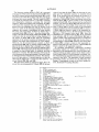
Keyboard processing routines 1 (DAY) through 8
20
(PM) all cause the display to be modi?ed by selecting a
portion of the display and then modifying it. They all
new digit. The ?rst flag to be examined is the day
expected ?ag. If the ?ag is set, a test is made to deter
mine if the new key input is between the values of l and
7 inclusive. If not, an error is indicated. Otherwise, the
value is used to obtain the proper segment enable which
will illuminate the indicated day and this value is in
deal with a set of pointers kept in temporary bytes.
These pointers identify the interpretation of the digit
keys (0-9) that will follow. For example the value in one
of the pointers will determine if the next number that is
entered will be considered to be part of the combination
to unlock the controller of the present invention.
serted into the display buffer in the day position. The
The DAY routine (1) will set the day portion of the
day-expected flag is also reset to zero. Then, return is
taken to the MCL. When the day-expected ?ag is not
set, the combination-expected flag is examined. If such
display to blank and then theday-expected flag to 1 to
indicate that a digit entered should be considered a
value to be put into the day display portion of the
flag is set, the digit-number-expected flag is used to
buffer. In addition, the review-?ag is set to its non-ini
determine which switch (of the 4 shown in FIG. 2) is to
be used for comparison. The chosen switch is compared
tialized state (see REVIEW key description). Finally,
return is taken to the MCL.
.
>
The START routine (2) will ?rst test to see if the
35
to the key being processed. If they do not match, then
an error has been encountered in entering the combina
day-expected ?ag is set. If it is, the error light will be lit
tion. This results in the combination-expected flag being
and return taken to the MCL. Otherwise, the START
?eld of the dislay will be set to blanksand then the
reset, the error light being lit, and return taken to the
point to the right-hand digit of the STOP minute ?eld.
expected ?ag is not set, the minute-expected ?ag is
MCL. If the switch and the key match, then the digit
right-hand digit of the hours ?eld will be set to display 40 number-expected flag is tested to see if the last key has
a 0. Also, the hour-expected ?ag is set to point to the
been processed. If not, then the routine increments the
right-hand digit of the START minute ?eld. The
digit-number-expected ?ag and returns to the MCL. If
AM/PM-expected flag is set to point to the AM/PM
the last key has been processed, the routine resets the
portion of the START display ?eld. Finally, return is
keyboard locked ?ag and returns to the MCL.
taken to the MCL.
45
When the combination-expected flag is not set, the
The STOP routine (3) will ?rst test to see if the day
hour-expected ?ag is examined. If the flag is set, the key
expected flag is set. If it is, the error light will be illumi
being depressed is to be the new right-hand digit in the
nated and return taken to the MCL. Otherwise, the
hour ?eld. This is done by ?rst moving the current
STOP ?eld of the display will be set to blanks and then
right-hand digit to the left to become the new left-hand
the right-hand digit of the hours ?eld will be set to
digit. If the digit so moved is 0, instead of moving all,
display a 0. Also, the hour-expected ?ag ‘is set to point
a blank is inserted into the left-hand digit. Then the new
to the right-hand digit of the STOP hour ?eld of the
key value is inserted as the new right-hand digit. Fi~
display. In addition, the minute-expected ?ag is set to
nally, return is taken to the MCL. When the hour
The AM/PM-expected ?ag is setv to point to the 55 examined. If the flag is set, the key being depressed is to
AM/PM portion of the STOP display ?eld. Finally,
be the new right-hand digit in the minute ?eld. This is
return is taken to the MCL.
I
done by ?rst moving the current right-hand digit to the
The UNLOCK KEYBOARD routine (4) will pre
left to become the new left-hand digit. Then the new
condition the Digit routine so that the combination
key value is inserted as the new right-hand digit. Fi
which will unlock the keyboard may be entered. To 60 nally, return is taken to the MCL. Thereafter, if none of
accomplish this, the UNLOCK KEYBOARD routine
the expected ?ags are set, the key is ignored and return
will set the combination-expected ?ag to 1 and reset the
is taken to the MCL.
digit-number-expected to 1. Finally, return is taken to
The Colon (:) routine (6) will reset the hour-expected
the MCL.
flag to zero. The minute-expected ?ag is then tested. If
There is one common routine for handling all of the 65 it isn’t set, an error is indicated. If it is set, then this
processing when a digit key isdepressed. This Digit
routine (5) ‘will use the various pointers to decide which
?eld of the display (when appropriate), will receive the
routine will cause further digit keys to be considered as
part of the minutes ?eld. In addition, this routine will
move 0’s into the minutes ?eld as speci?ed by the mi
19
4,279,012
20
nutes-expected ?ag. Finally, return is taken ‘to the
start time is a .1 as are such bits thereafter until the stop
MCL.
The AM routine (7) will ?rst test the AM/FM
expected ?ag. If it isn‘t set, an error is indicated. If set,
the value of AM is inserted into the location speci?ed
time is reached.
The REVIEW routine (18) is used to recall the
entries that have been programmed for a given day.
When the routine starts it tests if it has been initialized.
The initialized ?ag is reset by the DAY routine to indi
cate that any successive REVIEW will require initial
ization. After the REVIEW routine has performed the
initialization needed, the initialized ?ag will be set so
that further activations of the review key will retrieve
by the AM/PM-expected ?ag and three of the time
related digit expected ?ags are reset. Thus the hour
expected, minute-expected, and the AM/FM-expected
?ags are all reset.
The PM routine (8) will ?rst test the AM/FM
expected ?ag. If it isn’t set, an error is indicated. If set,
the value of PM is inserted into the location speci?ed by
the AM/PM-expected ?ag and three of the time related
digit expected ?ags are reset. Thus the hour-expected,
minute-expected, and the AM/PM-expected ?ags are
succeeding intervals rather than commencing with
12:00 AM. The initialization consists of setting a tempo
rary buffer to represent 12:00 AM of the current day
(day as speci?ed in the display buffer). This temporary
buffer is used as a pointer and is made to sequence
The LOCK KEYBOARD routine (9) will set the
keyboard status to locked and reset all four time-related
through all of the BIT-MAP values corresponding to
the day in question. The value in this buffer is main
tained until the review routine is again initialized. The
digit-expected ?ags. Thus, day-expected, hour
expected, minute-expected, and AM/PM-expected
20 bit which is a 1 is searched for. If the temporary buffer
all reset.
buffer is used as a pointer into the Bit-Map and the next
?ags are all reset. Also, the combination-expected ?ag is
reaches 12:00 AM, both START and STOP display
set to zero. Then, return is taken to the MCL.
buffer ?elds are set to blank. If a 1 is found, the value in
The SET TIME routine (10) will move the START
the temporary buffer is moved to the START display
?eld and the temporary buffer is used to ?nd the next-0
return is taken to the MCL. The DISPLAY TIME 25 in the Bit-Map. If the temporary buffer reaches 12:00
routine (11) will move the current time-of-day to the
AM of the next day, the value is set to 12:00 AM. In any
display buffer and set the time-of-day in display ?ag to
case, the temporary buffer is moved to the STOP ?eld
1. Finally, return is taken to the MCL. The CLEAR
of the display buffer and return is made to the MCL.
ERROR routine (12) will reset the error light and re
As has been seen hereinbefore, a Bit-Map has been
turn to the MCL. The BEGIN PROGRAM routine 30 utilized to store on/off information by bit representa
(13) will set the program ?ag to on (1) and return to the
tions, with each bit representing a time interval of thirty
MCL. The END PROGRAM routine (14) will set the
minutes. It has been seen however that more or less than
program ?ag to off (0) and return to the MCL. The
thirty minutes may have been so represented. An alter
CLEAR MEMORY routine (15) will set each of the 42
native embodiment to such Bit-Map is shown in FIG.
bytes which represent the Bit-Map to 0 and return to 35 12. The memory table of FIG. 12 is used to store time
the MCL. The CLEAR DAY routine (16) will set each
range information by use of slot entries. As shown,
of the 6 bytes in the Bit-Map associated with the current
there are included eight slots, however, by expanding
day to 0 and return to the MCL.
the memory table, additional slots may be had. Each
The STORE routine (17) allows the operator to enter
slot speci?es a time period for the operation of the appli
new information into the Bit-Map. The information that 40 ance under control. For each slot, there is an entry for
is inserted into the Bit-Map is the interval de?ned by the
each day of the week. FIG. 12 illustrates entries, by way
start and the stop times of the display. This interval is
of example, for day 3 (Wednesday). The designation
expanded if it is not on a 0 or 30 minute boundary. The
(0,0) means that there is no entry. Thus, non~zero entries
STORE routine starts by converting the values in the
specify time periods for appliance operation. Thus, on
stop display ?eld into interval form and testing to see if 45 Wednesday, the appliance will be on from 7:00 AM to
?eld of the dislay buffer to the time-of-day buffer. Then,
the minute value is 00 or 30. If not 00 or 30, the interval
8:30 AM as shown for the entry in slot 3, and so on as
value of the stop ?eld is incremented to point to the next
shown for the entries in slots 5 and 7. As shown, slots
highest interval. Thus if the values in the minutes ?eld
are allotted for additional entries. However, such
is 1:15 AM, it will be converted so that the internal
entries need not be made in a sequential manner by slot
value represents 1:30 AM. Once this is done, the inter 50 number. That is, an entry of (6:00 PM, 7:00 PM) may
nal time is tested to see if it points to 12:00 AM (mid
have been entered in any slot, for example, slot 1, and
night). If it does, the interval value is set to point to the
not necessarily slot 6.
_
?rst value for the next day. Thus the internal vale to the
It can be seen that various changes may be made to
stop time will point to that Bit-Map entry which corre
the controller of the present invention without depart
sponds to the half-hour interval beginning with the 55 ing from the spirit and scope thereof. For example, it
rounded-up stop time value. With the stop value con
can be seen that the Bit-Map may have a different orga
verted, the START is converted (the conversion rou
nization or format of information. Further, the control
tine will round the start time down to the nearest lower
ler may have been programmed for operation for longer
half-hour interval) and a test is performed to insure that
than a seven day period, for example, one month or
the start value is less than the stop value. If this is not 60 even one year. The devices under control could have
true, an error is indicated. The Bit-Map value corre
sponding to the start value is set to l (to indicate con
been operated independently, i.e., on a different pro
grammed basis, by partially reproducing the controller
nected devices on). The start valve is incremented by 30
of the present invention. That is, not all functions would
minutes and tested against the stop value. If the new
have to be reproduced, e.g., the time of day generation
value is less than the stop value, the routine continues 65 logic. It can further be seen that the relay, which is
setting the proper bits in the Bit-Map. When the new
controlled for applying power to the appliance, may
value reaches the stop value, return is taken to the
have been included in the appliance itself with low
MCL. Thus, the bit in the Bit-Map corresponding to the
power lines coupling the controller and the relay in the