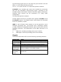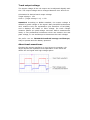
1
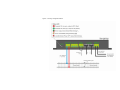
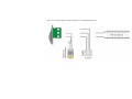
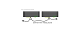
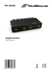
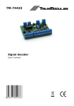
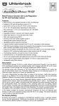
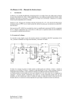
TM-26782 Digital booster II User's manual © 2015 BioDigit Ltd. All rights reserved. It is forbidden to reproduce and/or publish the contents of the present document in any form including electronic and mechanical design without the written permission of BioDigit Ltd. Safety warning During the operation of the device the specified technical parameters shall always be met. At the installation the environment shall be fully taken into consideration. The device must not be exposed to moisture and direct sunshine. A soldering tool may be necessary for the installation and/or mounting of the devices, which requires special care. During the installation it shall be ensured that the bottom of the device should not contact with a conductive (e.g. metal) surface! Contents Features and properties .......................................................... 2 Technical parameters: ............................................................ 2 Short description ................................................................... 3 Applicable supply units ........................................................... 3 Grounding and power supply of the booster ............................... 3 Supply voltage ...................................................................... 4 Connectors ........................................................................... 4 Signals .................................................................................5 Thermal protection ................................................................. 6 Switching-in/-out of the output voltage ..................................... 7 Feedback of the operating status.............................................. 7 Startup delay ........................................................................ 7 Recovery delay ......................................................................8 Short-circuit current ...............................................................8 Polarity change current limit .................................................... 8 Track output voltage .............................................................. 9 About track waveforms ........................................................... 9 Programming of the parameters ............................................. 10 Guarantee and legal statement .............................................. 12 Features and properties Developed for DCC/MM systems Short-circuit protected output with 3A limit Switching mode – high efficiency No heat sink required Comprehensive DCC CV programming Track voltage regulation Control from rail signal and LocoNet Remote switching on/off as device decoder Status feedback to the LocoNet Acoustic warning of short-circuit Delayed switch-on Automatic restart possibility after short-circuit Automatic reversal of polarization (loop reversing method) Easily portable compact design Technical parameters: Dimensions: 150x65x25 mm Idle mode current consumption: ~50mA Max. input current: 4000mA Short-circuit protection: 3000mA (max. 1 sec.) Automatic recovery time: 5-60 sec. (adjustable) Automatic reversal of polarization: Yes (loop reversing method) Start-up delay: 5-60 sec. (adjustable) Supply voltage: 12-24V AC/DC Output voltage: 9-19Vpeak (adjustable) Connection/disconnection by switch address : Yes (1-2048) LocoNet status support: Yes (GPON, GPOFF, IDLE) LocoNet feedback support: Yes (1-2048) Supported signal format: NMRA DCC / Motorola Short description The digital booster can amplify the track signal in digital systems. It enables higher load currents for tracks divided into independent sections. Applicable supply units A TM-87380 type 230V safety mains transformer is proposed for supplying the booster. Parameters of the transformer: Output voltage: 16V AC Max. output current: 5A Power rating: 80VA Input voltage: 230V AC Other transformers type with similar parameters can also be applied. (16V AC, min. 80VA) Grounding and power supply of the booster To avoid interferences and ground-loops, in larger networks that containing more boosters, it is required to operate the boosters with a common grounding point. The booster is weakly connected to ground when connection to the LocoNet connector is performed (through 100KOhm internal resistor). In case the length of the network (exceeding 40-50m) requires the use of a separate thicker common wire, the GND connector of the booster shall be used for connecting the common heavy ground wire. (See Figure 3.) Attention! This common ground is not the protection earth contact of power plugs. More details: http://www.wiringfordcc.com/booster.htm (English) Attention! Each booster shall be powered by an own supply unit. More boosters shall never be powered from a common power source! When the booster is operated from LocoNet, the signal arriving from the centre (or the previous booster) shall always be connected to the left LocoNet connector and the extension branch into the right LocoNet connector. Supply voltage The booster can be supplied by DC or AC as well. In order to achieve appropriate dissipation at the bridge rectifier of the booster, it is definitely preferred to use AC supply. The AC supply voltage shall never exceed 18V AC! Connectors The receiving possibilities of the booster synchronizing signal are described below. Since the booster can be adapted to various systems, it can be perfectly used if supplied from any of its inputs. Solely fully insulated track sections with both rails cut shall be supplied by the digital booster! DCC OUT: Boosted signal output. It is required to pay attention to the correct polarity during connection. In case the isolated rail section is of reversed polarity compared to the previous section, the booster may give a shortcircuit signal when the train changes the sections. Only one sync source can be used at a time. The booster shall never be used with synchronizing of rail signal and signals of other source simultaneously. The signal source detection is automatic. C D E: Synchronizing signal can be received from the rail signal or from C D E connection. This can be applied if neither of the other input signals is available or it is not required to ensure a separate synchronizing signal for the booster. The input can be used also for receiving the synchronizing signal of centers. In this case it shall be considered that a short-circuit status at the previous booster / maybe the centre can cause the breaking of the synchronizing signal from the rail. Now the given booster will shut down, i.e. the output will be turned off. The “C”, “D” inputs and the “E” output has galvanic isolation. LOCONET: At a LocoNet type centre the LocoNet bus connection also has the DCC/Other synchronizing signal. According to the LocoNet system the booster contains two RJ12 (6p6c) connectors, whereby more devices can be connected in a daisy chain configuration. The input has galvanic isolation. Certain digital centres are provided with separate LocoNet T and LocoNet B outputs. The digital booster shall always be connected to the "B" (Booster) output. GND: In case of larger track systems it can be required to use a separate grounding wire. The booster has a discharge resistor (>100K resistance) integrated between point 1 and point 2 of its GROUND connector. The assignment of the GND connector is as follows: 1. GND Left: LocoNet grounding point (core 2 and 5) 2. GND Right: Internal grounding point of the booster Signals The booster has status LED to show following operating statuses: STATUS LED Mode Dark Red blinking without sound Red Green Orange/Green blinking with beep sound Red blinking with beep sound The device is out of operation. No supply voltage. Delay after start-up. The device operates. No synchronizing signal. The device operates. Synchronizing signal is OK. Short circuit error. The booster detected short circuit condition on the RAIL output. The booster is overheated, the output has been turned off. Red short blinking The booster received LocoNet Global Power OFF command from the digital center, and the output is turned off. Prevent the booster from being under continuous short-circuit status. If the device indicates more short-circuits in short intervals it shall be determined whether this was caused by overload or real short-circuit. Overload shall be tested by removing some engines or waggons or other loads from the given track section to examine the presence of the short-circuit. Warning! Please also use a proper wire diameter at the booster power input, and the track output. If the applied wire is too thin, the short circuit protection will never occur, and the poorly connected or thin wires can cause fire. For comparison: The booster has more than 60W output power, and the common 20-30W soldering irons can also make fire! The booster is a high current device, and please discuss with electronics technician about wiring and the needed wire diameter for your layout. The recommended minimum wire diameter is AWG-20 (approx. 0.5mm2) Thermal protection The booster has an integrated thermal protection. In case the internal temperature exceeds 75°C, the booster stops with an overheat signal. If the internal temperature decreases below 50°C, the outputs can be turned on again. Attention! Tripping of the thermal protection during permanent operation generally means insufficient wiring and/or a low-capacity transformer. Never open the device, when the thermal protection tripped for faster cool-down! Switching-in/-out of the output voltage If the synchronizing signal is missing or regularly contains errors, the output will be automatically turned off to protecting the connected devices from faulty operation. The output of the booster is provided with the possibility of remote switching-in/out by accessory commands. The address can be adjusted by traditional CV settings. Default status of the remote control is "Not permitted" (address = 0). The address is contained by the CV1 and CV9 and can be calculated as follows: e.g. Required address: 1410 1410/256 = 5 with remainder 130 CV1 value: 130 CV9 value: 5 For disable this feature, write 0 to CV1 and CV9. Feedback of the operating status Feedback of the operating status works by traditional feedback addresses, to the LocoNet system. Default status of the feedback is "Not permitted" (address = 0). The address of the device giving the feedback is contained by the CV33 and the CV34 and can be calculated as follows: e.g. Required address decimal value: 509 509/256 = 1 with remainder 253 CV33 value: 253 CV34 value: 1 For disable this feature, write 0 to CV33 and CV34. Startup delay Startup delay can be adjusted in a wide range. With this delay it can be avoided that faulty data get on the rail from the digital centre before it is started. The startup delay can be adjusted between 0 and 60 sec. by the CV36 in one second steps. Recovery delay In case of short-circuit the booster automatically resets. Due to the delay the booster will not be permanently overloaded. The recovery delay can be adjusted between 5 and 60 sec. by the CV37 in one second steps. Automatic recovery can be disabled by writing 0 the CV37. Short-circuit current If the booster is used for smaller (less consumption) sections, it is practicable to adjust the short-circuit current to a lower value for the protection of the model railroad layout wires and the devices. The short-circuit tripping current can be adjusted between 0.5A and 3A in 0.1A steps using the CV38. e.g. Required short-circuit tripping current: 2.5A 2.5A = 2.5/0.1A => CV38 = 25 Short-circuit delay: 0.5-1 sec. Polarity change current limit The booster can be applied also as an automatic reverse loop. Loop reversing will automatically occur in case of sudden current change provided that automatic polarity change is permitted. The polarity change current limit can be adjusted between 0,5A and 3A in 0,1A steps using the CV39. e.g. Required polarity change current limit: 1.5A 1.5A = 1.5/0.1A => CV39 = 15 To disable this feature, write 0 to CV39. Attention! It is practicable to adjust the polarity change current limit at a lower value. Thus the sudden "stalling" of the vehicle passing along the section can be avoided. At polarity change there is no short-circuit delay. Track output voltage The output voltage of the rail output can be adjusted digitally with CVs. The output voltage can be changed between 9.0V and 19.0V. Calculation for desired track output voltage: Target voltage = 15V CV40 = (Target voltage * 10) = 150 Attention! According to NMRA standard, the output voltage is defined by peak voltage of the signal. Many handheld multimeters can’t measure truly the squarewave (the waveform of DCC/MM), and it displays not stable or false voltage. For track voltage measure please use peak-voltage converter before measurement leads, or use professional multimeter which can measure the real peak voltage, or use oscilloscope to determine the track voltage! We prefer use our TM-64643 handheld storage oscilloscope, easy to operate and LiPo battery powered. About track waveforms Checking the output waveform on your layout is necessary. On larger layouts the impedance and capacitance of the track can distort the rail signal with high voltage spikes. The distorted rail signal can damage the locomotive decoders. If the voltage spikes are larger than 5-10V the checking of connectors and wires are recommended first. Solutions 1. Check your connections (the poor connection also can make large voltage spikes.) 2. Try to separate the large layout into smaller power districts to prevent large inductance. Use more boosters to electrical separation. 3. Use our small TM-32273 spike filter module to lower the voltage spikes and fix the bad condition of your track. This module can absorb the transients. Programming of the parameters The parameters can be modified by the DirectCV programming method. The booster supports the Write, Read and Verify commands. To achieve this programming method the “C” and “D” connector of the booster is to be connected directly to the PROG OUT or normal output connector of the digital centre. During programming attention shall be paid to the appropriate power supply of the booster (PWR IN). The booster responds towards the centre by an ACK (acknowledge) known in decoder programming, provided that the entered value is valid. If after programming the digital centre returns an Error, the value to be entered into the CV is outside the valid range, or the address of the CV is not suitable. Parameter name Default Range Switch address (lower bits) 0 0-255 Version number Manufacturer identifier 61 -* Switch address (upper bits) 0 0-8 Feedback address (lower bits) 0 0-255 Feedback address (upper bits) 0 0-8 Startup delay (sec.) 2 0-60 Recovery delay (sec.) 5 0-60 Short-circuit tripping current 40 5-40 (Ampere*10) 39 Polarity change current limit 20 5-40 (Ampere*10) 40 Track voltage (Voltage*10) 15 90-190 * Entering any value into the CV8 forces reset to the default parameter values. CV address 1 7 8 9 34 35 36 37 38 Attention! The booster(s) shall always be separately connected to the programming signal, otherwise all boosters connected to a common signal line will be programmed to equal values. Guarantee and legal statement Each parameter of the device will be submitted to comprehensive testing prior to marketing. The manufacturer undertakes one year guarantee for the product. Defects occurred during this period will be repaired by the manufacturer free of charge against the presentation of the invoice. The validity of the guarantee will cease in case of improper usage and/or treatment. Attention! By virtue of the European EMC directives the product can be used solely with devices provided with CE marking. The mentioned standards and brand names are the trademarks of the firms concerned. TrainModules ®: BioDigit Ltd. LocoNet®: Digitrax Inc. NMRA DCC: National Model Railroad Association TrainModules® – BioDigit Ltd. Cziraki street 26-32. H-1163, Budapest Tel.:+36 1 46-707-64 http://www.trainmodules.com/ Figure 1. Wiring of digital booster Figure 2. Connecting different railsync signals to TM-26782 digital booster Figure 3. Large layout network grounding