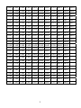
1
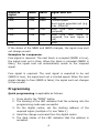
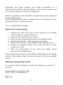
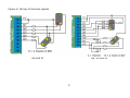
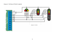
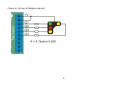
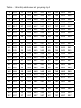
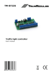
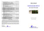
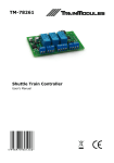
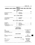
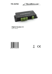
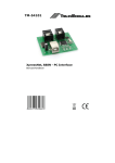
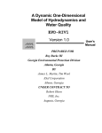
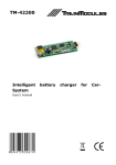
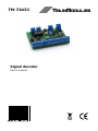
TM-74433 Signal decoder User's manual © 2011 BioDigit Ltd. All rights reserved. It is forbidden to reproduce and/or publish the contents of the present document in any form including electronic and mechanical design without the written permission of BioDigit Ltd. Safety warning During the operation of the device the specified technical parameters shall always be met. At the installation the environment shall be fully taken into consideration. The device must not be exposed to moisture and direct sunshine. A soldering tool may be necessary for the installation and/or mounting of the devices, which requires special care. During the installation it shall be ensured that the bottom of the device should not contact with a conductive (e.g. metal) surface! Contents Safety warning ...................................................................... 1 Properties ............................................................................. 2 Technical parameters ............................................................. 2 Short description ................................................................... 2 Wiring .................................................................................. 2 Automatic train manipulation ................................................... 3 Programming ........................................................................ 4 Table of decoder CVs .............................................................. 6 Guarantee and legal statement ................................................ 7 1 Properties Handling the signalling system of several countries External control possibility Train manipulation Smooth light changing (bulb simulation) Optional separate supply Quick programming possibility Detailed DCC CV programming Handling of one or more signals Low idle mode current consumption Technical parameters Supply voltage: 7-24V Idle mode current consumption: 20 mA Max. current consumption: 80 mA Dimensions: 58x47 mm Short description The module serves for controlling the light signals. The decoder recognizes the signalling system of several countries whereby always the appropriate view will appear on the light signals connected to the decoder. It is provided with inputs and outputs capable of manipulating trains. If also the external control inputs are used, an automatic wagon distance control system can be achieved as well. Wiring The supply voltage is connected to the "POWER" terminals. The rail signal of the digital system is connected to the "DCC IN" terminals (Figure 1a) The light signal is connected to the Q1-Q8 outputs (depending on the signal and the country). If we do not wish to use external supply for the module, the "POWER" and "DCC IN" terminals can be commoned (Figure 1b). 2 Automatic train manipulation The automatic train manipulation is the integrated part of each light signal decoder; it requires no external device at all. RAIL OUT: This output is for supplying the rail block in front of the signal. BREAK IN: The output of the brake control device is connected to this input (Figure 2). Leave the "BREAK IN" terminals empty if no brake control device is available. In this case, when the light signal stops the engine, the block in front of the signal gets into voltage-free condition (the engine stops immediately). The following inputs can be used for train manipulation: RED: Light signal to red. When the input is activated, the light signal changes to red; in case also the BRK input is active, the rail block preceding the active light signal will be supplied by the brake control device (the engine stops). GRN: Light signal to manual free. The status of the "NRED" and "NBOD" inputs influences the free signal. BRK: Sensing of engine along the block – change-over of block supply NRED: Input for the feedback of the red status of the next signal. It influences the free signal view of the signal. NBOD: Input for the feedback of the occupation of the next block. It influences the free signal view of the signal. Modifying the signal view The status of the NRED and NBOD inputs modifies in each case the actual signal view when the free signal is sent. The rules are as follows: 3 Required signal Free Free NRED NBOD Signal sent out False True False False Free False True Free True True Stop - - Free Limited speed. Next signal expected red (e.g. max. 40km/h) Stop (the next block is occupied) Stop (the next block is occupied, the next signal is red) Stop If the status of the NRED and NBOD changes, the signal view sent out change as well. Examples for a sequence: Free signal is required. The next block is occupied (NBOD is true), the signal sent out is Stop. When the block is released (NBOD is false), the signal sent out automatically resets to the required signal. Free signal is required. The next signal is expected to be red (NRED is true), the signal sent out is Limited speed. When the next signal changes to free (NRED is false), the signal sent out changes to free as well. Programming Quick programming is applicable as follows: 1. Press shortly the "PROG" button 2. The blinking of the LED indicates that the entering into the programming mode was successful 3. On the digital centre, set the starting address of the required signal (multiple of 4, see Table 1) 4. Send the change command from the digital centre 5. The dark status of the LED indicates that the address is accepted. 4 Thereafter the signal decoder will accept commands on 4 addressed following the starting address; each required signal view can be set by means of these four addresses. Another procedure is the DirectCV programming mode supported by any digital centre. The CV programming mode is suitable also for the selection of the signalling system of a given country. * CV = Configuration Variable Steps of CV programming: 1. Connect the "DCC IN" input of the decoder to the digital centre output for programming rail 2. Switch on the decoder power supply 3. Enter into the Programming menu of the digital centre 4. Select the Direct CV - Byte programming mode 5. Enter the CV number of the setting to be modified (e.g. 1) 6. Confirm the entered number then enter the new CV value as well (e.g. 190) 7. After the confirmation of the value the digital centre performs the programming. The programming process can be different depending on the digital centres; thus always study the user's manual of the given digital centre. Address programming by CVs For example: desired address is 1045. This address is consists of two CVs. Desired address divided by 256: 1045 / 256 = 4 remainder 21 CV1 = 4 CV9 = 21 5 Table of decoder CVs CV 1 7 8 9 112 113 Description Address LSB Version Mfg. ID / Reset* Address MSB Country code 0 = Universal** 1 = Hungarian 2 = German 3 = Dutch 4 = Belgian Light signal type (see- table of types) Range 1-255 0-7 Default value 1 61 0 0 * CV8 = 8 restore factory defaults ** 4 pcs 2 aspects light signal Light signal type table (CV 113) CV112 CV113 0 0 = 4 pcs 2 aspects light signal 1 0 = 4 aspects light signal 1 = 3 aspects section light signal 2 = 2 aspects light signal 3 = 4 aspects repeat-signal 2 0 = Hp0, Hp1, Hp2 and Vr0, Vr1, Vr2 1 = Hp0, Hp1, Hp2, Sh1, Vr0, Vr1, Vr2 3 0 = 3+1 aspects light signal 4 0 = 4 aspects light signal 6 Guarantee and legal statement Each parameter of the device was submitted to comprehensive testing prior to marketing. The manufacturer undertakes one year guarantee for the product. Defects occurred during this period will be repaired by the manufacturer free of charge against the presentation of the invoice. The validity of the guarantee will cease in case of improper usage and/or treatment. Attention! By virtue of the European EMC directive the product can be used solely with devices provided with CE marking. The mentioned standards and branch names are the trademarks of the firms concerned. TrainModules – BioDigit Ltd Kerepesi street 92. H-1144, Budapest Made in Hungary. Tel.:+36 1 46-707-64 http://www.trainmodules.hu/ 7 Figure 1: Connections of the signal decoder a) In case of external supply b) In case of common supply Figure 2: Wiring of the signal decoder with train manipulation 1 Figure 3: Wiring of Hungarian signals * Resistors: 4,7 KOhm 0,6W 2 Figure 4: Wiring of German signals Hp and Vr Hp, Sh and Vr 3 Figure 5: Wiring of Dutch signals 4 Figure 6: Wiring of Belgian signals 5 Table 1: Starting addresses at grouping by 4 1 101 201 301 401 501 601 701 801 901 5 105 205 305 405 505 605 705 805 905 9 109 209 309 409 509 609 709 809 909 13 113 213 313 413 513 613 713 813 913 17 117 217 317 417 517 617 717 817 917 21 121 221 321 421 521 621 721 821 921 25 125 225 325 425 525 625 725 825 925 29 129 229 329 429 529 629 729 829 929 33 133 233 333 433 533 633 733 833 933 37 137 237 337 437 537 637 737 837 937 41 141 241 341 441 541 641 741 841 941 45 145 245 345 445 545 645 745 845 945 49 149 249 349 449 549 649 749 849 949 53 153 253 353 453 553 653 753 853 953 57 157 257 357 457 557 657 757 857 957 61 161 261 361 461 561 661 761 861 961 65 165 265 365 465 565 665 765 865 965 69 169 269 369 469 569 669 769 869 969 73 173 273 373 473 573 673 773 873 973 77 177 277 377 477 577 677 777 877 977 81 181 281 381 481 581 681 781 881 981 85 185 285 385 485 585 685 785 885 985 89 189 289 389 489 589 689 789 889 989 93 193 293 393 493 593 693 793 893 993 97 197 297 397 497 597 697 797 897 997 1001 1101 1201 1301 1401 1501 1601 1701 1801 1901 2001 1005 1105 1205 1305 1405 1505 1605 1705 1805 1905 2005 1009 1109 1209 1309 1409 1509 1609 1709 1809 1909 2009 1013 1113 1213 1313 1413 1513 1613 1713 1813 1913 2013 1017 1117 1217 1317 1417 1517 1617 1717 1817 1917 2017 1021 1121 1221 1321 1421 1521 1621 1721 1821 1921 2021 1025 1125 1225 1325 1425 1525 1625 1725 1825 1925 2025 1029 1129 1229 1329 1429 1529 1629 1729 1829 1929 2029 1033 1133 1233 1333 1433 1533 1633 1733 1833 1933 2033 1037 1137 1237 1337 1437 1537 1637 1737 1837 1937 2037 1041 1141 1241 1341 1441 1541 1641 1741 1841 1941 2041 1045 1145 1245 1345 1445 1545 1645 1745 1845 1945 1049 1149 1249 1349 1449 1549 1649 1749 1849 1949 1053 1153 1253 1353 1453 1553 1653 1753 1853 1953 1057 1157 1257 1357 1457 1557 1657 1757 1857 1957 1061 1161 1261 1361 1461 1561 1661 1761 1861 1961 1065 1165 1265 1365 1465 1565 1665 1765 1865 1965 1069 1169 1269 1369 1469 1569 1669 1769 1869 1969 1073 1173 1273 1373 1473 1573 1673 1773 1873 1973 1077 1177 1277 1377 1477 1577 1677 1777 1877 1977 1081 1181 1281 1381 1481 1581 1681 1781 1881 1981 1085 1185 1285 1385 1485 1585 1685 1785 1885 1985 1089 1189 1289 1389 1489 1589 1689 1789 1889 1989 1093 1193 1293 1393 1493 1593 1693 1793 1893 1993 1097 1197 1297 1397 1497 1597 1697 1797 1897 1997 1