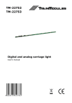
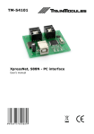
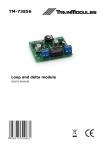
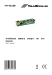
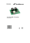
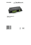
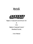
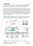
1
TM-75461 SmartLIO - Control desk (LocoNet) User's manual © 2011 BioDigit Ltd. All rights reserved. It is forbidden to reproduce and/or publish the contents of the present document in any form including electronic and mechanical design without the written permission of BioDigit Ltd. Safety warning During the operation of the device the specified technical parameters shall always be met. At the installation the environment shall be fully taken into consideration. The device must not be exposed to moisture and direct sunshine. A soldering tool may be necessary for the installation and/or mounting of the devices, which requires special care. During the installation it shall be ensured that the bottom of the device should not contact with a conductive (e.g. metal) surface! Contents Safety warning ...................................................................... 1 Features and properties .......................................................... 2 Technical parameters ............................................................. 2 Short description ................................................................... 2 Attachable devices and its applications ...................................... 2 Wiring .................................................................................. 3 Connection of input devices ..................................................... 3 Connection of output devices ...................................................3 Power supply, external power .................................................. 4 Programming, assignment of addresses .................................... 4 Reset to default position .........................................................6 Guarantee and legal statement ................................................ 7 1 Features and properties Designed to LocoNet system 8 programmable input/output 2 analogue input Fast programming mode Optional external supply Technical parameters Input supply voltage: 7-24V Stand-by current consumption: 20 mA Max. current consumption: 100 mA Dimensions: 92x34 mm Short description Any layout can be controlled by traditional pushbuttons and potentiometers, and even LEDs and sound signals with this module. The operation mode and the address assigned to the buttons and the feedback outputs can be programmed quickly and easily. These programmed addresses are stored in non-volatile memory, and furthermore it queries the current status of the railway switches and signals from the digital command station at the time of device connection. Attachable devices and its applications - Pushbutton (for resumed railways switches and for signals and sound signals) - Switch / arresting pushbutton (for permanent, selectable outputs) - LED, light emitting diode (for feedbacks – even between the switchboards) - Buzzer (for sound signal) - Potentiometer (for controlling a locomotive) - Light sensor - photoresistor 2 Wiring It is practical to install the whole module in a box, like the traditional analogous switchboard. LEDs, switches, pushbuttons and potentiometers can be drilled to the front panel of the switchboard. If you use several modules (i.e. you need more output/input), it is advisable to install these modules inside the switchboard. You do not need any external device, everything is included in the module – except for some connection options (e.g. use of engine reverse switch). Connection of input devices In case of digital inputs the input is active if the given point is connected to GND (common ground point). If you "release” the input, it is switched back to the original normal, inactive status. In case of analogous inputs (e.g. potentiometer) the power supply voltage of the inputs must be between 0 and 5 V. The circuit uses a range with a hysteresis about 2.5 V (half the power supply voltage) for easy center zero speed. Thus larger (several degree) deviation from the mid position is still 0 speed, which makes operation easier. See Figure 2-3. Connection of output devices The LED and the buzzer can be connected towards +5 V and 0 V (always with the right polarity). If you connect the LED between +5 V and 0 V it will perform reversed operation (the LED will illuminate when it is not active), whereas if you connect it between the output and 0 V, it will perform normal operation (the LED will illuminate when it is active). See. Figure 4. 3 Power supply, external power Power supply source can be selected with "Power select" pin header. In left position it will receive power supply from the LocoNet bus, in the right position it can be supplied through the ‘Ext. Power’ connector. When powered from LocoNet always pay attention to the LocoNet's load capacity. Programming, assignment of addresses Matching the physical inputs and outputs with the digital system is performed by programming the addresses. Two separate programming modes are available for programming the inputs and outputs. Programming and addressing of a connection point to make it an input 1. Press pushbutton labelled ‘Prog’ for one second. 2. Quick blinking of the LED ‘Prog’ will indicate that the module is in programming mode. 3. You can shift the row of LEDs behind the connector by pressing pushbutton ‘Prog’ for a short period, which will indicate the current connection point to be programmed. 4. Shift the row of LEDs to the desired connection. 5. Issue command ‘switching’ by digital centre or a manual controller (normal railway switch). 6. This time the LED ‘Prog’ on the module indicates with a short blink that means the address and programming is completed. 7. If you want to programme further inputs, please repeat the procedure from point 4. 8. You can exit from programming mode by pressing ‘Prog’ for at least 2 seconds. 4 Programming a connection point to become an analog input This programming method can be implemented only on the two analogous inputs. 1-4: It is the same as the procedure described above 5a. Please get the address of the desired engine in the digital centre. You can programme the address of the engine in a range of addresses between 1 and 9999. 5b. You can programme an engine address by command ‘Switch’ described above; in this case the address of the railway switch is identical to the engine (it will obtain that address), but the address only between 1 and 2048. 6. After assigning an address the LED ‘Prog’ on the module will indicate with short blinks (as described above) that the address has been taken up by the connection point. 7-8: It is the same as points 7 and 8 described above. Programming a connection point to become an output 1. Press pushbutton labelled ‘Prog’ for at least 2 seconds. 2. Slow blinking of LED ‘Prog’ will indicate that you are in the mode for programming an output. 3. You can shift the row of LEDs behind the connector by pressing pushbutton ‘Prog’ for a short period, which will indicate the current connection point to be programmed. 4. Shift the row of LEDs to the desired connection. The LED connected to the connection point will also blink. 5. Send command ‘switching’ by digital centre or a manual controller (normal railway switch). 6. This time the LED ‘Prog’ on the module indicates with a short blink that means the address and programming is over. 7. If you want to programme further output, please repeat the procedure from point 4. 8. You can exit programming mode by pressing ‘Prog’ for a longer period (at least 2 seconds). 5 In this case the output will start operation simultaneously with feedback signals or the railway switch. You may use for getting feedback for occupancy, exchanging signals between panels or for indicating the position of the railway switches or signals. If your railway switch does not have a built-in feedback system, the module will detect it and turn the output to command “switching”, so it will feedback the status of the last switch (which is identical to the position of the railway switch then). Reset to default position Follow the next procedure to reset the factory default settings. 1. Unplug the LocoNet or switch off external power source. 2. Press pushbutton ‘Prog’. 3. Reconnect the module (or turn on external power source). 4. Release pushbutton ‘Prog’. Default setting: Terminals number 1 2 3 4 5 6 7 8 9 10 Operation mode Address Digital input, switch mode Digital input, switch mode Digital input, switch mode Digital input, switch mode Digital input, switch mode Digital input, switch mode Digital input, switch mode Digital input, switch mode Analogue input, no operation mode Analogue input, no operation mode 1 2 3 4 5 6 7 8 0 0 6 Guarantee and legal statement Each parameter of the device will be submitted to comprehensive testing prior to marketing. The manufacturer undertakes one year guarantee for the product. Defects occurred during this period will be repaired by the manufacturer free of charge against the presentation of the invoice. The validity of the guarantee will cease in case of improper usage and/or treatment. Attention! By virtue of the European EMC directives the product can be used solely with devices provided with CE marking. The mentioned standards and branch names are the trademarks of the firms concerned. TrainModules – BioDigit Ltd Kerepesi street 92. H-1144, Budapest Made in Hungary. Tel.:+36 1 46-707-64 http://www.trainmodules.hu/ 7 Figure 1. Wiring of module Figure 2. Two position switch / arresting pushbutton, pushbutton, three position switch 1 Figure 3. Potentiometer, locomotive speed control: (Center zero / Direction change switch) 2 Figure 4. Wiring output devices - LEDs and buzzer 3