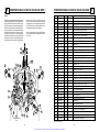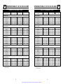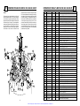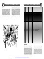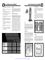
1
Artisan Technology Group is your source for quality
new and certified-used/pre-owned equipment
• FAST SHIPPING AND
DELIVERY
• TENS OF THOUSANDS OF
IN-STOCK ITEMS
• EQUIPMENT DEMOS
• HUNDREDS OF
MANUFACTURERS
SUPPORTED
• LEASING/MONTHLY
RENTALS
• ITAR CERTIFIED
SECURE ASSET SOLUTIONS
SERVICE CENTER REPAIRS
Experienced engineers and technicians on staff
at our full-service, in-house repair center
WE BUY USED EQUIPMENT
Sell your excess, underutilized, and idle used equipment
We also offer credit for buy-backs and trade-ins
www.artisantg.com/WeBuyEquipment
InstraView REMOTE INSPECTION
LOOKING FOR MORE INFORMATION?
Visit us on the web at www.artisantg.com for more
information on price quotations, drivers, technical
specifications, manuals, and documentation
SM
Remotely inspect equipment before purchasing with
our interactive website at www.instraview.com
Contact us: (888) 88-SOURCE | [email protected] | www.artisantg.com
LIQUID CYLINDER
LIQUID CYLINDER
OPERATING MANUAL
• Cryo-Cyl 80HP
• Cryo-Cyl 120, 180, 230LP
• Dura-Cyl MCR 160MP/HP
• Dura-Cyl MCR 180MP/HP
• Dura-Cyl MCR 200MP/HP
• Dura-Cyl MCR 230MP/HP
• Dura-Cyl MCR 265MP/HP
• Dura-Cyl 160MP/HP
• Dura-Cyl 180MP/HP
• Dura-Cyl 200MP/HP
• Dura-Cyl 230MP/HP
• Dura-Cyl 265MP/HP
Artisan Technology Group - Quality Instrumentation ... Guaranteed | (888) 88-SOURCE | www.artisantg.com
PREFACE
MVE LIQUID CYLINDER USERS MANUAL
NOTES
This edition of the MVE Liquid Cylinder Users Manual
documents Release I and all subsequent releases of
the Chart Inc. MVE Dura-Series cryogenic liquid
cylinders users manual. This edition has information
regarding both MVE Dura-Cyl and Cryo-Cyl cryogenic
liquid cylinders. Unless otherwise noted, the term
Dura-Cyl/ Cryo-Cyl Series refers to the Dura-Cyl 160MP,
Dura-Cyl 160HP, Dura-Cyl 180MP, Dura-Cyl 180HP,
Dura-Cyl 200MP, Dura-Cyl 200HP, Dura-Cyl 230MP,
Dura-Cyl 230HP, Dura-Cyl 265MP, Dura-Cyl 265 HP,
Cryo-Cyl 80 HP, Cryo-Cyl 120 LP, Cryo-Cyl 160LP,
Cryo-Cyl 180LP, Cryo-Cyl 230LP, Dura-Cyl MCR 160MP,
Dura-Cyl MCR 160 HP,Dura-Cyl MCR 180MP, Dura-Cyl
MCR 180HP, Dura-Cyl MCR 200MP, Dura-Cyl MCR
200HP, Dura-Cyl MCR 230MP, Dura-Cyl MCR 230HP,
Dura-Cyl MCR 265 MP and Dura-Cyl MCR 265 HP
model cryogenic liquid cylinders.
Section 5 explains how to determine the type or
model of the various cryogenic liquid cylinders.
This manual is intended to provide the user with the
information necessary to operate and maintain the
Dura-Cyl/Cryo-Cyl Series liquid cylinders. It is important that users of the above mentioned cryogenic
liquid cylinders read fully and understand the information contained in this manual.
Sections 16 and 17 are set up to aid with the routine
maintenance and adjustments needed to operate the
Dura-Cyl/Cryo-Cyl Series liquid cylinder.
Section 6 lists the performance features and technical specifications of all the Dura-Cyl/Cryo-Cyl Series
liquid cylinders. This should help in determining the
model of cryogenic liquid cylinder needed for a specific application.
Section 7 talks about the general theories of operation of the Dura-Cyl/Cryo-Cyl Series models.
Section 8 thru 15 deals with the actual operation of
the various Dura-Cyl/Cryo-Cyl Series models. These
sections can be used as quick reference guides and
will provide the specified information needed to operate each model.
Section 18 shows how to use the Dura-Cyl/Cryo-Cyl
Series in specific applications. Various accessories
are discussed as they aid the different applications.
The manual is divided into the following sections to
make it easier to look up information concerning a
particular model of the Dura-Cyl/Cryo-Cyl Series.
Any comments or suggestions related to this manual are encouraged and should be forwarded in
writing to:
Section 3 and 4 discuss the safety requirements
needed to operate any of the Dura-Cyl/Cryo-Cyl
Series. Additional safety information on cryogenics
or the gases carried can be obtained from the
Compressed Gas Association.
REVISION LOG
LETTER
DATE
DESCRIPTION
G
9/01/92
New release with PLC and Dura III Models
H
5/01/94
New release with Dura-Cyl and Cryo-Cyl Models
I
10/01/95
Added Cryo-Cyl 80HP, Cryo-Cyl 265 MP & HP;
Chart, Inc.
Marketing Coordinator
PO Box 1312
Canton, GA 30114
Deleted Dura-Mite
J
3/01/96
Add Dura-Cyl MCR, Delete Cryo-Cyl MP & HP Model (except 80 HP)
K
5/01/98
Addition of new Dura-Cyl HP LCCM module
L
1/23/01
General Revisions and Updates
Any comments or suggestions related to this manual
are encouraged and should be forwarded in writing to:
Chart, Inc.
Marketing Coordinator
PO Box 1312
Canton, Georgia 30114
Telephone or fax Chart at one of the numbers listed below.
International:
952-882-5090
Fax:
952-882-5008
Technical Service / Emergencies:
800-400-4683
Fax:
800-232-9683
1
A1
Artisan Technology Group - Quality Instrumentation ... Guaranteed | (888) 88-SOURCE | www.artisantg.com
2 TABLE OF CONTENTS
1 Preface . . . . . . . . . . . . . . . . . . . . . . . . . . . . A1
11 Operation of Dura-Cyl MCR-HP
General
Filling
Parts Identification
Operation Pressure
Liquid CO2 Withdrawal
Gas withdrawal
Service and Maintenance
2 Table of Contents . . . . . . . . . . . . . . . . . . . A2
3 Safety
...........................1-2
4 Safe Handling . . . . . . . . . . . . . . . . . . . . . 2 - 4
5 Introduction . . . . . . . . . . . . . . . . . . . . . . . 5 -8
General
Cylinder Design
Cylinder Identification
Distributor Filling Responsibilities
12 Operation of Dura-Cyl HP
General
Filling
Parts Identification
Operation Pressure
Liquid CO2 Withdrawal
Gas withdrawal
Service and Maintenance
6 Features . . . . . . . . . . . . . . . . . . . . . . . . .9 - 13
General
Performance
Specifications
7 Theory of Operation
General
Filling
Liquid Withdrawal
Gas Withdrawal
Economizer System
. . . . 34 - 39
16 Service and Maintenance
General
O2 Cleaning
Adjustments
MCR Regulator
LCCM Regulator
Level Gauge
Changing Services
10 Operation of Dura-Cyl MP . . . . . . . . . 28 - 33
General
Parts Identification
Operating Pressure
Gas Withdrawal
Service and Maintenance
. . . . . . 46 - 49
. . . . . . . . . 55 - 62
17 Applications and Accessories
18 Safety Bulletin
WARNING
(2) A stainless steel neck tube that is designed not to
break in case of a minor accident, such as a liquid
cylinder being inadvertently tipped over.
Nitrogen and argon vapors in air may dilute the
concentration of oxygen necessary to support or
sustain life. Exposure to such an oxygen deficient
atmosphere can lead to unconsciousness and serious injury, including death.
WARNING
15 Troubleshooting . . . . . . . . . . . . . . . . 52 - 54
Loss of Vacuum
Pressure Too High
Pressure Too Low
9 Operation of Dura-Cyl MCR- MP . . . . 22 - 27
General
Filling
Parts Identification
Operating Pressure
Gas Withdrawal
Service and Maintenance
3
gen; particularly oil, grease, kerosene, cloth, wood,
paint, tar, coal dust, and dirt which may contain oil
or grease. DO NOT permit smoking or open flames
in any area where oxygen is stored, handled, or
used. Failure to comply with this warning may result in serious personal injury.
(3) A vacuum maintenance system specifically designed to provide long life and safety provisions.
14 Cryo-Cyl/ Dura-Cyl Base Design . . . . . 50 - 51
Footring Design
Caster Base Design
Base Identification Table
Parts Identification
. . . . . . . . . . 18 - 21
Chart has conducted a rigid test program for liquid
cylinders, both internally and through an independent
testing laboratory, to verify the safety of Chart equipment. MVE cylinders are safely designed with the
following features:
(1) An exclusive all stainless steel support system designed to withstand many years of rugged service.
. . . . . . . . . 40 - 45
13 Operation of Cryo-Cyl 80 HP
General
Filling
Parts Identification
Gas Withdrawal
Service and Maintenance
. . . . . . . . . . . . . .14 - 17
8 Operation of Cryo-Cyl LP
General
Filling
Parts Identification
Operating Pressure
Liquid Withdrawal
Service and Maintenance
SAFETY
(4) Safety relief devices to protect the pressure vessel and vacuum casing, sized and selected in
accordance with CGA Pamphlet S-1.1 “Safety Relief
Devices for Cylinders.” The safety of the inner pressure vessel is controlled by a pressure relief valve and
rupture disc. A reverse buckling rupture disc protects
the vacuum casing from overpressure.
The Dura-Cyl/Cryo-Cyl Series, with its stainless
steel support system is designed, manufactured,
and tested to function normally for many years of
service. Chart does not suggest or warrant that it is
ever safe to drop a liquid cylinder or let it fall over
in oxygen or any other cryogenic service. In the
event a liquid cylinder is inadvertently dropped,
tipped over, or abused, slowly raise it to its normal vertical position. Immediately open the vent
valve to release any excess pressure in a safe
manner. As soon as possible, remove the liquid
product from the vessel in a safe manner. If the
vessel has been used in oxygen service, purge it
with an inert gas (nitrogen). If damage is evident
or suspected, return to Chart prominently marked
“LIQUID CYLINDER DROPPED, INSPECT FOR
DAMAGE”.
While Chart equipment is designed and built to rigid
standards, no piece of mechanical equipment can
ever be made 100% safe. Strict compliance with
proper safety and handling practices are necessary
when using a liquid cylinder or other compressed gas
equipment. We recommend that all our customers reemphasize safety and safe handling practices to all
their employees and customers. While safety features
have been designed into the unit and safe operations
are anticipated, it is essential that the user of these
liquid cylinders carefully read to fully understand all
WARNINGS, CAUTION and Notes listed in this safety
section and enumerated below. Also read to fully understand the information provided in the Safety
Bulletins for Oxygen and Inert Gases located in
Section 19 of this Manual. Periodic review of the
Safety Summary is recommended.
WARNING
Before removing cylinder parts or loosening fittings, completely empty the liquid cylinder of liquid
and release the entire vapor pressure in a safe
manner. External valves and fittings can become
extremely cold and may cause painful burns to
personnel unless properly protected. Personnel
must wear protective gloves and eye protection
whenever removing parts or loosening fittings.
Failure to do so may result in personal injury because of the extreme cold and pressure in the
cylinder.
WARNING
. . . . . 62 - 63
. . . . . . . . . . . . . . . . . . 64 - 65
Excess accumulation of oxygen creates an oxygen
enriched atmosphere (defined by the Compressed
Gas Association as an oxygen concentration above
23 percent). In an oxygen enriched atmosphere,
flammable items burn vigorously and could explode. Certain items considered non-combustible
in air may burn rapidly in such an environment.
Keep all organic materials and other flammable
substances away from possible contact with oxy-
A2
1
Artisan Technology Group - Quality Instrumentation ... Guaranteed | (888) 88-SOURCE | www.artisantg.com
4 SAFE HANDLING
SAFE HANDLING
This section describes and illustrates proper cylinder
handling procedures. Major considerations for liquid
cylinder handling are summarized as follows:
Caution
Only use replacement equipment which is compatible
with liquid oxygen and has been cleaned for oxygen
use. Do not use regulators, fittings, hoses, etc., which
have been previously used in compressed air service.
Similarly, do not use oxygen equipment for compressed air. Failure to comply with these instructions
may result in serious damage to the liquid cylinder.
•
Caution
Dura-Cyl/Cryo-Cyl Series cryogenic liquid cylinders
should be moved using an appropriate liquid cylinder cart
or dolly. Do not roll liquid cylinders by handling rings.
Dura-Cyl/Cryo-Cyl Series liquid cylinders must be used
and stored in a vertical position except for normal cart or
dolly movement. Do not lay, store, or ship a liquid cylinder
on its side. When necessary to transport a liquid cylinder
by truck, use a power lift gate, crane, or inclined ramp to
lower the liquid cylinder. If the truck bed and dolly are
not at the same height, do not attempt to manually lift or
slide a liquid cylinder on or off a tuck bed. Failure to comply with these procedures may result in damage to the
liquid cylinder.
Dura-Cyl/Cryo-Cyl Series should be moved only
by utilizing an appropriate cylinder cart, roller
base, or overhead hoist. See section 17 for approved equipment.
•
Do not roll a liquid cylinder by the handling ring.
•
Dura-Cyl/Cryo-Cyl Series cylinders should always
be stored and operated in a vertical position.
•
Never lay, store, or ship a cylinder on its side.
•
When loading (or unloading) a cylinder onto a
truck, use a power lift gate, crane, or an inclined
ramp. Never attempt to manually lift or slide a liquid cylinder on or off of a truck bed.
Dura-Cyl/Cryo-Cyl Series liquid cylinder can be safely
handled by using a cylinder cart, roller base, or an
overhead hoist. When moving the unit, keep the unit
upright at all times except for those instances when it
is slightly tipped for loading or unloading.
4
This method is used when frequent and short distance
moves of a liquid cylinder are required. Before utilizing this method of transportation, make sure the area
over which the liquid cylinder is to be moved is flat and
smooth.
Preferred Handling Procedures
Figure B illustrates the preferred cylinder handling procedures. It shows the proper way to approach a
cylinder when using a pneumatic-tired hand truck. It
shows how to engage the pickup hook in the post slot
and illustrates it properly engaged. It then illustrates
how to tilt the cylinder back once the pickup hook and
post slot are engaged. The approximate tilt position of
the cart should be maintained when transporting a
cylinder.
The hard rubber-tired hand truck (or a hand truck having swivel rear wheels) can be used in place of a
pneumatic-tired hand truck. As with the roller base,
use of these methods should be limited to facilities
having relatively smooth floors.
A semi-permanent handling carriage can be used
which locks the Dura-Cyl/Cryo-Cyl Series liquid cylinder to the base for transporting cylinders. This
arrangement is ideal for those users having the capability of filling their own liquid cylinders.
Alternate Procedures
The use of a four wheel roller base that has been designed expressly for transporting a liquid cylinder is
acceptable. See Section 17 for approved equipment.
Refer to Section 17 of this manual for ordering information on these handling accessories.
1
3
Approaching container
engaging pickup hook
in the post slot.
Tilt container down on
wheels and roll away.
Dura-Cyl/Cryo-Cyl Series liquid cylinders are durable
liquid cylinders designed to withstand common handling; however, abusing a unit may damage the liquid
cylinder to the extent that it must be returned to the
factory for repair.
Preferred Lifting Procedure
The Dura-Cyl/Cryo-Cyl Series liquid cylinders are provided with a ring on the top of the liquid cylinder. The
ring is designed to protect the plumbing components
and should not be used to handle or lift the liquid cylinders. The ring is attached to the cylinder with two or
four posts. Each post has a lifting hole in it that can
be used to lift or attach a handling cart.
2
Proper pickup hook/post
slot engagement.
To lift a Dura-Cyl/Cryo-Cyl Series liquid cylinder, attach the properly sized hooks and chains into both of
the holes and lift vertically. Figure A shows how a
chain system can be used to lift the liquid cylinder. The
spreading bar is the preferred method, but the double
chain system is acceptable.
Figure A
Figure B
2
3
Artisan Technology Group - Quality Instrumentation ... Guaranteed | (888) 88-SOURCE | www.artisantg.com
4 SAFE HANDLING
INTRODUCTION
Transport Canada for the transporting of liquid nitrogen, oxygen, and argon. They are authorized by
Transport Canada for the transporting of carbon dioxide and nitrous oxide with an exemption.
General
Use Straps
Do Not
Use Chains
Use A Handtruck
And A Power Liftgate
The Chart, Inc. MVE Dura-Series cryogenic liquid
cylinders and the Cryo-Cyl Series cryogenic liquid
cylinders (figure D) are double walled, vacuum and
multi-layer insulated cylinders designed for the transportation and storage of liquefied gases. These liquid
cylinders are designed for the transportation and storage of cryogenic products which can be used as either
gas or liquid. All of the Dura-Cyl or Cryo-Cyl Series
liquid cylinders can be used for liquid argon, liquid
nitrogen, and liquid oxygen. The Dura-Cyl HP or
Cryo-Cyl HP can also be used for transporting liquid
carbon dioxide (CO2) or liquid nitrous oxide (N2O).
The inner pressure vessel is constructed of stainless
steel and supported within an outer stainless steel
vacuum jacket. The support system is an all stainless
steel internal support, designed for low heat leak and
high strength.
The illustration in Figure E shows the major components of the Dura-Cyl/Cryo-Cyl Series liquid cylinders.
The space between the inner and outer vessel makes
up the insulation system. Multiple-layer insulation and
high vacuum assures long holding time. The insulation
system is designed for long term vacuum retention
and is permanently sealed at the factory. The vacuum
space is protected from over pressurization by the use
of a reverse buckling rupture disc.
The Cryo-Cyl Series liquid cylinders have model distinctions for low pressure liquid withdrawal (LP). For
Dura-Cyl series of liquid cylinders model distinctions
for medium pressure liquid and gas withdrawal (MP),
high pressure liquid and gas withdrawal (HP) and the
very high pressure liquid and gas withdrawal (VHP).
See section 6, Specifications, for more detail.
The outer vacuum jacket of the liquid cylinder contains
an internal vaporizer which converts the cold liquid to
gas. Refer to Section 6, figure I and J, for the gas withdrawal curves. The internal pressure building system
allows for immediate use of the cylinder by automatically building pressure to the preset operating
pressure and maintaining it there during gas withdrawal. Refer to Section 6, figure H, for the pressure
builder's performance curves.
The Dura-Cyl/Cryo-Cyl series liquid cylinders also
have capacity distinctions; the number after their
name that designates net capacity in liters (the DuraCyl 180 indicates 180 liters capacity). See section 6,
Specifications, for more detail.
The Dura-Cyl series of liquid cylinders have two styles
of pressure regulation, the LCCM pressure manifold
on the Dura-Cyl and the combination pressure regulator on the Dura-Cyl MCR.
Figure C
Transporting Procedures
The Dura-Cyl/Cryo-Cyl Series liquid cylinders are designed to withstand the normal handling associated
with transportation by truck.
Do Not use chains. Chain tie downs will scratch the
finish and could crush or dent the vacuum jacket.
Figures C also shows the proper method of unloading
a cylinder from a truck. Note that the pneumatic-tired
hand truck should be used and that the cart and liquid
cylinder are lowered to the ground by use of a power
lift gate.
Figure C illustrates how a cylinder should be secured
in a truck for transportation. A nylon or other suitable
strap should be used. The use of a strap prevents
scratching on the surface and provides a reliable tie
down arrangement. Never use a chain type binder.
Each liquid cylinder is equipped with a stainless steel
ring to protect the plumbing components. The ring on
the Cryo-Cyl is connected to the cylinder with two handling post; the Dura-Cyl uses four handling posts. The
posts have slots for ease in handling with a hand truck
or an overhead hoist. Hand trucks that can be supplied
by MVE are described in Section 17.
The portable liquid cylinders provide a reliable, convenient, and economical method for the transportation
and delivery of liquefied gas products. They are primarily used as a self-contained gas supply. They can
be used with a variety of accessories such as the M-45
Manifold to provide larger gas storage capacities.
Refer to Section 17 for details on applications.
The Dura-Cyl/Cryo-Cyl Series cryogenic liquid cylinders
are constructed with all operating controls situated at
the top of the cylinder for ease in gas withdrawal and
liquid dispensing operations. In a stand-alone operating
environment it enables the user, through use of the vent,
liquid, pressure building, and pressure relief devices,
to completely control the liquid cylinder's operation.
Cylinder Design
The Dura-Cyl/Cryo-Cyl Series liquid cylinders are designed, manufactured, and tested to the requirements
of the U.S. DOT and Transport Canada 4L specification. They are specifically authorized by the U.S.
Department of Transportation for the transporting of
liquid nitrogen, oxygen, argon, carbon dioxide, and
nitrous oxide. They are specifically authorized by
4
To protect the inner pressure vessel from over pressurization, the unit includes a safety pressure relief
valve. The liquid cylinders are further protected from
5
Artisan Technology Group - Quality Instrumentation ... Guaranteed | (888) 88-SOURCE | www.artisantg.com
5
5 INTRODUCTION
INTRODUCTION
5
Cylinder Identification
gauge protector color is an easy way to determine
the pressure rating of a liquid cylinder.
There are 24 Dura-Cyl/Cryo-Cyl Series liquid cylinders described in this manual. They vary in size,
capacity, pressure, gas service and various plumbing features. It is important that these liquid cylinders
can be easily identified.
The data plate (Figure G) is permanently attached
to the handling post of the liquid cylinder. The data
plate shows the serial number and pressure rating
for that cylinder. Do not remove or alter the data
plate in any way.
The following table shows each model by name and
indicates its capacity and pressure rating. The sight
Model
Figure D
Protection
Ring
over pressurization by a bursting disc that acts as a
secondary relief device. These devices meet the
requirements of CGA Pamphlet S-1.1 “Pressure
Relief Device Standard — Part 1 — Cylinders For
Compressed Gases.”
Liquid Level
Gauge
Handling
Slot
Safety Relief
Devices
Handling
Post
Plumbing
Controls
A back control regulator is used to build and maintain
operator pressure while assuring a no-loss operation
under normal usage during gas withdrawal service.
The no loss portion of the regulator (referred to as the
economizer) allows gas withdrawal directly from the
vapor space of the cylinder until liquid cylinder head
pressure is reduced to the normal operating range.
This important feature is useful whenever a liquid
cylinder has been inactive for a period of several days
or whenever normal heat leak may have created an
increase in head pressure.
Reverse
Buckling
Rupture Disc
Outer
Vacuum
Jacket
Multi Layered
Insulation
Inner
Pressure
Vessel
For precise regulation of the outlet gas, add a final line
gas regulator at the gas use connection. The operating
pressure can be increased to the pressure control
valve setting (if necessary) by changing the regulator.
Vacuum
Space
Foot
Ring
These MVE liquid cylinders provide a complete selfcontained liquid or gas supply system for industrial,
laboratory, or hospital use.
Figure E
Gross Maximum Sight
Storage Operating Gauge
Capacity Pressure Protector
(Liter)
(PSIG)
Color
Cryo-Cyl 80 HP
85
350
orange
Cryo-Cyl 120 LP
120
22
yellow
Cryo-Cyl 180 LP
196
22
yellow
Cryo-Cyl 230 LP
240
22
yellow
Dura-Cyl 160 MP
176
230
blue
Dura-Cyl 160 HP
176
350
orange
Dura-Cyl 180 MP
196
230
blue
Dura-Cyl180 HP
196
350
orange
Dura-Cyl 200 MP
209
230
blue
Dura-Cyl 200 HP
209
350
orange
Dura-Cyl 230 MP
240
230
blue
Dura-Cyl 230 HP
240
350
orange
Dura-Cyl 265 MP
276
230
blue
Dura-Cyl 265 HP
276
350
orange
Dura-Cyl MCR 160 MP
176
230
blue
Dura-Cyl MCR 160 HP
176
350
orange
Dura-Cyl MCR 180 MP
196
230
blue
Dura-Cyl MCR 180 HP
196
350
orange
Dura-Cyl MCR 200 MP
209
230
blue
Dura-Cyl MCR 200 HP
209
350
orange
Dura-Cyl MCR 230 MP 240
230
blue
Dura-Cyl MCR 230 HP
240
350
orange
Dura-Cyl MCR 265 MP 276
230
blue
Dura-Cyl MCR 265 HP
350
orange
276
6
Figure G
7
Artisan Technology Group - Quality Instrumentation ... Guaranteed | (888) 88-SOURCE | www.artisantg.com
5 INTRODUCTION
FEATURES
3. Dispense only to knowledgeable users.
The filler must determine that the user is knowledgeable about the general characteristics of the
product and the proper safety precautions for
its use. Do not allow customers to fill their own
cylinders.
Chart is stating below the responsibilities of the filler of
any cryogenic liquid cylinder:
1. The cylinder must be in a safe condition.
4. Dispose of cylinders properly.
The filler is responsible for confirming that any
cylinder to be filled is in its proper working condition. This includes that:
To eliminate the risk of injury from the improper
reuse of cryogenic (vacuum jacketed) cylinders,
before disposal, destroy the cylinder’s pressure
retaining capability.
• It has an acceptable vacuum.
• The relief system is in place and functioning.
General
The performance of the vaporizer to convert cold liquid into gas is shown by how the outlet gas
temperature drops as the gas flow rate increases.
The MVE cryogenic liquid cylinders were designed to
furnish a convenient, reliable, and economical method
for the transportation and delivery of liquefied gases.
Important features of these liquid cylinders include:
100%
FULL
* The Dura-Cyl/Cryo-Cyl Series liquid cylinders are
constructed with an all stainless steel internal
support system designed for low heat leak and
high strength.
PRESSURE (PSIG)
Responsibilities of Distributor and
Fillers of Liquid Cylinders
* These cylinders are easily handled by one person.
• There is no structural damage to the cylinder.
2. Drill multiple holes through the cylinder and its
vacuum casing or otherwise puncture the tank.
2. Do not overfill the cylinder.
Do it yourself! Don’t assume it will be done by the
scrap dealer.
The cylinders are not to be filled beyond the
recommended filling weight for the liquid being
dispensed.
50%
FULL
10
0
25%
FULL
25%
FULL
Dura-Cyl Series
40
30
20
1. Purge the cylinder’s contents.
• All warning labels are in place and legible.
75%
FULL
120
110
100
90
80
70
60
50
* Gas stored in liquid form in a Dura-Cyl/Cryo-Cyl
Series liquid cylinder is more pure than gas
stored in conventional cylinders.
We recommend:
6
Cryo-Cyl 80HP
10
20
30
40
50
60
70
80
90 100
TIME (MINUTES)
* During periods of non-use, pressure will rise in a
cryogenic liquid cylinder. The highly efficient insulation system minimizes the rate of pressure
rise. This allows for a reasonable period of nonuse without any venting of product from the
pressure relief valve.
Figure H
Figure H illustrates the expected liquid cylinder pressure building rate (with liquid nitrogen) versus time.
* Internal pressure building and vaporization systems permit a continuous flow of gas without
need for an external vaporizer.
150
125
PRESSURE (PSIG)
* The pressure control regulator automatically
maintains working pressure with minimum product loss.
* Cylinders can be used singularly or can be manifolded to provide a continuous gas supply.
90% FULL
90% FULL
100
50
00
75
100 SCFH
500 SCFH
80% FULL*
70% FULL*
150 S
CFH
2000
SCF
H
75% FU
SC
FH
15%
LL*
FUL
L*
50
Performance
Dura-Cyl Series
17000 SCFH
24
The performance of a liquid cylinder can be shown in its
ability to hold a cryogenic liquid and dispense it as a gas.
Cryo-Cyl 80HP
EMPTY
10
20
30
40
50
60
70
80
TIME (MINUTES)
The normal evaporation rate (NER) is an indication of
how well the insulation system performs its ability to
hold cryogenic liquid. The Dura-Cyl/Cryo-Cyl Series
NER is shown on the specification chart on pages
14 thru 16. Figure L indicates how the insulation performance effects the holding time for CO2 or N2O.
Figure I illustrates how the pressure builder will maintain
delivery pressure at various flow rates. (See note 1 and 2)
The pressure building system can be measured by
how fast it can increase pressure in the liquid cylinder (Figure H) and how well it maintains pressure
while gas is being withdrawn from the cylinder
(Figures I and K).
Notes:
1. Curves assume liquid withdrawal from tank and
use of free standing vaporizer.
2. Pressure builder valve open and pressure control
regulator at 125 psi.
8
* Amount of liquid left at conclusion of test
Figure I
9
Artisan Technology Group - Quality Instrumentation ... Guaranteed | (888) 88-SOURCE | www.artisantg.com
6 FEATURES
FEATURES
CO2 W/P.B.@ 300 PSIG
200 SCFH
40
300 SCFH
300 SCFH
500 SCFH
300
(230 lb.
200
30
Pressure (PSIG)
TEMPERATURE OF EXITING GAS (NITROGEN) -˚F
350
50
400 SCFH
20
10
0
-10
40
60
80
Design Specification (DOT/CTC)
200 SCFH
500 SCFH
800 S
CFH
2 hr.
1 hr.
Figure J-1
120 LP
180LP
230 LP
20 (50.8)
20 (50.8)
20 (50.8)
26 (66.0)
39.5 (100.3)
51 (129.5)
63.5 (161.3)
54.8 (139.2)
165 (74.8)
165 (74.8)
210 (95.2)
290 (131.5)
See pg. 49
See pg. 21
See pg. 21
See pg. 21
4L
4L
4L
4L
292 (20.1)
100 (6.9)
100 (6.9)
100 (6.9)
Relief Valve Setting psig (BAR)
350 (24.1)
22 (1.5)
22 (1.5)
22 (1.5)
Normal Operating Pressure psig
75-175
10-100
10-100
10-100
(5.2-12.0)
(0.7-6.9)
(0.7-6.9)
(0.7-6.9)
• Nitrogen
3.0%
2.0%
1.5%
1.5%
• Oxygen or Argon
2.0%
1.4%
1.0%
1.0%
• CO2 or N2O
Normal Evaporation Rate
Figure K
Figure K illustrates continuous flow rates for CO2 and
N2O when a pressure-build coil is used and adequate
external vaporization is present (Dura-Cyl HP only).
Figure J-1 illustrates vaporizer performance for the
Dura-Cyl series liquid cylinders.
80 HP
DOT Service Pressure psig (BAR)
(BAR)
100
SATURATION PRESSURE (PSIG)
0.8%
–
–
–
Gross Capacity (liters)
(85)
(120)
(196)
(240)
Storage Capacity, Liquid (liters)
(80)
(110)
(185)
(230)
• Nitrogen
1670 (44)
–
–
–
• Oxygen
2089 (55)
–
–
–
• Argon
2040 (54)
–
–
–
• CO2
1634 (43)
–
–
–
1546 (41)
–
–
–
• Nitrogen, Oxygen, Argon
100 (3)
–
–
• CO2 or N2O
30 (1)
–
–
Liquid Level Gauge
Dial Type
Float
Float
Float
Construction Material
Stainless
Stainless
Stainless
Stainless
75-175
0-25 ➃
0-25 ➃
0-25 ➃
Storage Capacity, Gas cu. ft.(BAR)
60
PRESSURE (PSIG)
TEMPERATURE OF EXITING GAS (NITROGEN) -˚F
Empty Weight - lbs. ( kg.)
①
Fill Weight
350
200
20
2 hr.
N2O W/P.B.@ 300 PSIG
-20
0
Physical Characteristics
Diameter - inches. (cm.)
➂
Height - inches (cm.)
2000 SC
FH
/hr.)
1 hr.
300
MVE CRYO-CYL
SPECIFICATIONS
100 SCFH
60
6
50 SCFH
30
100 SCFH
0
150 SCFH
350
300
70˚
t
ien
mb
FA
30˚ F
nt
Ambie
(Relief Setting)
0˚ F Ambient
200
100
days
10
20
30
40
50
60
-30
Figure L
-60
0
20
40
60
80
Figure L illustrates Dura-Cyl HP holding times for
CO2 and N2O.
100
SATURATION PRESSURE (PSIG)
Figure J-2
• Nitrous Oxide
Gas Delivery Rate scfh (Nm3/hr.)②
Pressure Building Regulator
Figure J-2 illustrates vaporizer performance for the
Cryo-Cyl 80 HP.
psig
Performance data provided on the illustrations represents typical values. Actual values may vary
depending on ambient conditions and/or the condition of the liquids.
Notes:
1. Non-controlled environment – 80Þ F, 50%
Relative Humidity, light breeze at 120 psig outlet.
2. For controlled environment – 70Þ, 30 % Relative
Humidity, still air, subtract 20 Þ F.
3. For outlet gas pressure – ATM, subtract 5Þ F.
4. For outlet gas pressure – 80 psig, subtract 2Þ F.
5. For argon, add 10Þ F.
6. For oxygen, subtract 7Þ F.
7. Temperature obtained after one hour of continuous usage.
(BAR)
(5.2-12.0)
(0-1.7)
(0-1.7)
(0-1.7)
See pg. 46
See pg. 18
See pg. 18
See pg. 18
Finish
Stainless
Stainless
Stainless
Stainless
Base Construction
Stainless
Round
Stainless
Round or
Steel
Caster
Steel
Square
Footring
Caster
Connections
Footring
Notes:
① At lower relief valve settings, weights and capacities are higher (See Fill Weight Table)
② Peaks of up to 4 X continuous flow rates can be sustained for 5 minutes if the vaporizer coils are allowed to thaw in between.
➂ Height may vary on caster base models depending on specified wheel diameter.
➃ With optional pressure builder.
10
11
Artisan Technology Group - Quality Instrumentation ... Guaranteed | (888) 88-SOURCE | www.artisantg.com
6 FEATURES
FEATURES
160 MP
160 HP
180 MP
180 HP
MVE DURA-CYL & DURA CYL MCR
SPECIFICATIONS
MVE DURA-CYL & DURA CYL MCR
SPECIFICATIONS
6
200HP
200 MP
230MP
230HP
265MP
265HP
Physical Characteristics
Physical Characteristics
Diameter - inches. (cm.)
➂
Height - inches (cm.)
20 (50.8)
20 (50.8)
20 (50.8)
20 (50.8)
20 (50.8)
59.6 (151.3)
59.6 (151.3)
63.5 (161.3)
63.5 (161.3)
65.8 (167.1)
Empty Weight - lbs. ( kg.)
①
Fill Weight
250 (113.4)
280 (127.0)
260 (117.8)
300 (136.1)
280 (126.9)
See pg. 32
See pg. 44
See pg. 32
See pg. 44
See pg. 32
Design Specification (DOT/CTC)
4L
4L
4L
4L
4L
DOT Service Pressure psig (BAR)
200 (13.8)
292 (20.1)
200 (13.8)
292 (20.1)
200 (13.8)
Relief Valve Setting psig (BAR)
230 (15.9)
350 (24.1)
230 (15.9)
350 (24.1)
230 (15.9)
40-160
80-320
40-160
80-320
40-160
(2.8-11.0)
(5.5-22.0)
(2.8-11.0)
(5.5-22.0)
(2.8-11.0)
Normal Operating Pressure psig
(BAR)
Diameter - inches. (cm.)
➂
Height - inches (cm.)
20 (50.8)
26 (66.0)
26 (66.0)
26 (66.0)
26 (66.0)
65.8 (167.1)
54.8 (139.2)
54.8 (139.2)
59.8 (151.9)
59.8 (151.9)
Empty Weight - lbs. ( kg.)
①
Fill Weight
320 (145.1)
324 (147)
375 (170)
353 (160)
430 (195)
See pg. 44
See pg. 32
See pg. 44
See pg. 32
See pg. 44
Design Specification (DOT/CTC)
4L
4L
4L
4L
4L
DOT Service Pressure psig (BAR)
292 (20.1)
200 (13.8)
292 (20.1)
200 (13.8)
292 (20.1)
Relief Valve Setting psig (BAR)
350 (24.1)
230 (15.9)
350 (24.1)
230 (15.9)
350 (24.1)
80-320
40-160
80-320
40-160
80-320
(5.5-22.0)
(2.8-11.0)
(5.5-22.0)
(2.8-11.0)
(5.5-22.0)
• Nitrogen
1.85%
1.8%
1.8%
2.0%
2.0%
• Oxygen or Argon
1.2%
1.2%
1.2%
1.4%
1.4%
• CO2 or N2O
0.5%
–
0.5%
–
0.5%
(209)
(240)
(240)
(276)
(276)
(196)
(230)
(230)
(265)
(265)
Normal Operating Pressure psig
(BAR)
Normal Evaporation Rate
Normal Evaporation Rate
• Nitrogen
2%
2%
1.9%
1.9%
1.85%
1.4%
1.4%
1.3%
1.3%
1.2%
–
0.5%
–
0.5%
–
Gross Capacity (liters)
(176)
(176)
(196)
(196)
(209)
Storage Capacity, Liquid (liters)
(165)
(165)
(185)
(185)
(196)
• Oxygen or Argon
• CO2 or N2O
Gross Capacity (liters)
Storage Capacity, Liquid (liters)
Storage Capacity, Gas Cu. Ft. (Nm )
3
Storage Capacity, Gas Cu. Ft. (Nm3)
• Nitrogen
3685 (97)
3464 (91)
4099 (108)
3864 (102)
4375 (115)
• Oxygen
4577 (120)
4348 (114)
5096 (134)
4843 (127)
5435 (143)
• Argon
4448 (117)
4226 (111)
4961 (130)
4709 (124)
5290 (139)
• CO2
–
3382 (89)
–
3766 (99)
–
• Nitrous Oxide
–
3207 (84)
–
3574 (94)
–
350 (10)
350 (10)
350 (10)
350 (10)
400 (11)
• CO2 or N2O
–
110 (3)
–
110 (3)
–
Liquid Level Gauge
Dial Type
Dial Type
Dial Type
Dial Type
Dial Type
Stainless
Construction Material
Stainless
Stainless
Stainless
Stainless
psig
40-160
80-320
40-160
80-320
40-160
BAR
(2.8-11.0)
(5.5-22.0)
(2.8-11.0)
(5.5-22.0)
(2.8-11.0)
BAR
4734 (124)
5769 (152)
5438 (143)
6244 (164)
5930 (156)
7186 (189)
6811 (179)
• Argon
5019 (132)
6073 (160)
5763 (151)
6982 (183)
6634 (174)
• CO2
4011 (105)
–
4614 (121)
–
5305 (139)
3810 (100)
–
4378 (115)
–
5034 (132)
• Nitrogen, Oxygen, Argon
400 (11)
400 (11)
400 (11)
400 (11)
400 (11)
• CO2 or N2O
110 (3)
–
110 (3)
–
110 (3)
• Nitrous Oxide
Gas Delivery Rate scfh (Nm /hr.) ②
Liquid Level Gauge
Dial Type
Dial Type
Dial Type
Dial Type
Dial Type
Construction Material
Stainless
Stainless
Stainless
Stainless
Stainless
psig
80-320
40-160
80-320
40-160
80-320
BAR
(5.5-22.0)
(2.8-11.0)
(5.5-22.0)
(2.8-11.0)
(5.5-22.0)
MCR Pressure Control Combo Reg. Range
MCR Pressure Control Combo Reg. Range
Connections
Finish
Base Construction
5024 (132)
5157 (136)
LCCM Pressure Control Manifold Range
LCCM Pressure Control Manifold Range
psig
4113 (108)
• Oxygen
3
Gas Delivery Rate scfh (Nm3/hr.) ②
• Nitrogen, Oxygen, Argon
• Nitrogen
50-175
(3.4-12.0)
See pg. 28
Stainless
Stainless
Steel
Footring
150-350
(10.3-24.1)
See pg. 40
Stainless
Stainless
Steel
Footring
50-175
(3.4-12.0)
See pg. 28
Stainless
Stainless
Steel
Footring
150-350
(10.3-24.1)
See pg. 40
Stainless
Stainless
Steel
Footring
50-175
(3.4-12.1)
See pg. 28
Stainless
Stainless
Steel
Footring
Notes:
① At lower relief valve settings, weights and capacities are higher (See Fill Weight Table)
② Peaks of up to 4 X continuous flow rates can be sustained for 5 minutes if the vaporizer coils are allowed to thaw in between.
➂ Height may vary on caster base models depending on specified wheel diameter.
psig
150-350
BAR
(10.3-24.1)
See pg. 40
Stainless
Stainless
Steel
Footring
Connections
Finish
Base Construction
50-175
(3.4-12.0)
See pg. 28
Stainless
Caster
Base ➃
150-350
50-175
150-350
(10.3-24.1)
See pg. 40
Stainless
Caster
Base ➃
(3.4-12.0)
See pg. 28
Stainless
Caster
Base ➃
(10.3-24.1)
See pg. 40
Stainless
Caster
Base ➃
Notes: The DURA-CYL MP series is not approved for use with CO2 or N2O.
① At lower relief valve settings, weights and capacities are higher (See Table)
② Peaks of up to 4 X continuous flow rates can be sustained for 5 minutes if the vaporizer coils allowed to thaw in between.
➂ Height may vary on caster base models depending on specified wheel diameter.
➃ Dura-Cyl has square caster base & Dura-Cyl MCR has round caster base.
12
13
Artisan Technology Group - Quality Instrumentation ... Guaranteed | (888) 88-SOURCE | www.artisantg.com
THEORY OF OPERATION
7
General
THEORY OF OPERATION
Liquid cylinder operation is done completely with the
control valves located on the top of the tank. The
valves are labeled and color coded for easy identification: Fill/Liquid Valve – blue; Gas Use Valve –
green; Vent Valve – silver; Pressure Building Valve
– green.
The various liquid cylinders of the Dura-Cyl/Cryo-Cyl
Series have the same general operating characteristics. Each model of liquid cylinder has the ability to be
filled with a cryogenic product, build pressure inside
the vessel, and deliver either liquid or gas for a specific application.
The schematic, illustrations and table (figure M) show
how the plumbing circuitry operates for the four major models of liquid cylinders. It is important that the
operators be familiar with the plumbing control valves
and there functions.
The following section will discuss the theory behind
these operations. Later sections (section 8 thru 13)
will give a step by step procedure for the operation on
each specific models of liquid cylinder.
Item
6
3
6
8
2
6
8
2
9
5
2
5
6 8
1
9
2
4
1
9
9
4
4
VAPORIZER
PRESSURE
BUILDING
COIL
PRESSURE
BUILDING
COIL
Cryo-Cyl LP
Cryo-Cyl LP/
with PB Option
PRESSURE
BUILDING
COIL
Dura-Cyl MP/HP
Cryo-Cyl 80HP
The following recommendations should be used to optimize liquid cylinder filling:
* Keep the transfer lines as short as possible. Long
uninsulated transfer lines will result in higher fill
losses and longer fill times.
All MVE liquid cylinders are tested for performance
with low-purity liquid nitrogen. For this reason liquid
cylinders intended for use in another service should
be thoroughly purged with the applicable gas prior
to filling.
* Anytime liquid can be entrapped in a line between
two valves, the line must be equipped with a
safety relief device.
Gas Use Valve – Used for gas withdrawal.
2.
Fill / Liquid Valve – Used for filling or
liquid withdrawal operations.
3.
Pressure Control Valve – Used to isolate (on/off) the pressure control
regulator.
4.
Vent Valve – Used to vent pressure.
5.
Pressure Control Manifold– Used to
automatically maintain pressure .
6.
Pressure Gauge – Indicates cylinder
pressure.
7.
Combination Regulator MCR– Used
to automatically maintain pressure.
8.
Pressure Relief Valve – Used to limit
pressure in the liquid cylinders.
9.
Liquid Level Gauge – Used to approximate the liquid contents of the liquid
cylinder.
When filling a liquid cylinder with a cryogenic liquid,
the transfer may be made with a centrifugal pump or
through a pressure transfer operation.
* Do not over fill; fill only to the weight allowable by
specification.
Pump Transfer
* Use a minimum number of bends, valves and reducers.
* Use as large a transfer line as possible – at least
1/2" ID.
Chart recommends the "Lo-Loss" system for liquid
cylinder filling. For information ask for the Lo-Loss cutsheet, P/N 11210548 from Chart.
LIQUID
IN
SPRAY
HEADER
Pressure Transfer
Dura-Cyl MCR MP/HP Series
Dura-Cyl MP/HP Series
1
9
9
8
2
8
VAPORIZER
LIQUID
GAS
IN
OUT
6
Figure O
Liquid
GAS
1/2
F
7
E
LIQUID
NITRO
GEN
Pressure Transfer
1/2
240
280
PRESSURE
BUILDING
COIL
1
4
5
6
Plumbing Controls and Function
1.
8
3
7
The liquid cylinder should be visually inspected before
every fill for possible damage, cleanliness and suitability for its intended gas service. If damage is
detected (e.g. serious dents, loose fittings, etc.) remove it from service and repair the unit as soon as
possible.
* Conduct the filling operation in as short a time as
possible.
Dura-Cyl/Cryo-Cyl Series
5
Filling Procedures
7
F
320
E
LIQUID
NITRO
GEN
4
Liquid will always flow from a vessel of higher pressure
to one with low pressure. This method is commonly
used to fill liquid cylinders by connecting a transfer line
between the delivery source and the Fill/Liquid valve of
the liquid cylinder. The transfer takes place as the vent
valve of the liquid cylinder is opened. This allows gas to
escape and lowers the pressure in the liquid cylinder.
This method should always be used for liquid only vessels such as the Cryo-Cyl LP. Figure N shows the
pressure transfer method of filling.
BUIL
DER
ES
PR
E
SUR
3
VAPORIZER
3
2
PRESSURE
BUILDING
COIL
Figure M
Figure N
14
15
Artisan Technology Group - Quality Instrumentation ... Guaranteed | (888) 88-SOURCE | www.artisantg.com
7 THEORY OF OPERATION
THEORY OF OPERATION
Economizer
Closed
Pump Transfer
The pump transfer method lowers the product losses
associated with filling. Liquid may be pumped into the
cylinder so that venting is not necessary. The vent
valve on the liquid cylinder has a spray header that
will splash the incoming cold liquid onto the somewhat warmer gas in the tank. The cold liquid will
actually collapse the vessel pressure while being
sprayed into the warmer gas. This method of filling
works well with vessels that are used regularly and
do not warm up between fills. Figure O shows the
pump transfer method.
Pressure
Builder
CLOSED
7
fer line. Normal liquid withdrawal operations are performed at lower pressure (approximately 22 psig) to
reduce flash-off losses and splashing. For this reason,
the pressure building valve is customarily closed during
liquid withdrawals. Transfer of liquid at higher pressures can lead to excessive splashing of the cryogenic
liquid which could result in burns to the operator and/or
nearby personnel. All personnel should be fully instructed in the cautions associated with handling
cryogenic fluids and the proper clothing and protective
gear to be used.
OPEN
GAS
OUT
GAS IN
Liquid
Withdrawal
Gas Withdrawal
VAPORIZER
VAPORIZER
When a Dura-Cyl liquid cylinder is used for gas withdrawal, the normal operating pressure range is from
approximately 75-175 psig and the pressure relief
valve has a set pressure of 230 psig When a DuraCyl HP liquid cylinder is used for gas withdrawal, the
normal operating pressure range is from approximately
100-350 psig and the pressure relief valve has a set
pressure of 350 psig On both liquid cylinders the economizer portion of the control regulator is automatically
set approximately 15 psig higher than the pressure
building portion of the control regulator.
LIQUID
LIQUID IN
PRESSURE
BUILDING
COIL
Figure Q
The supply of gaseous product is the primary operation of the liquid cylinder. An additional regulator must
be added to the gas use valve to step down the pressure to the application. The liquid cylinder is usually
at a high pressure after the filling and delivery operation. When it is connected to the gas application and
the gas use valve and pressure building valves are
opened, it will automatically deliver gas.
WARNING: Before conducting a gas (or liquid)
withdrawal operation, make sure protective eyeglasses and gloves are being used.
Economizer
Open
PRESSURE
BUILDING
COIL
The Dura-Cyl MP/Dura-Cyl MCR MP model with a 230
psi relief valve operates between the pressure building
setting (125 psig) and the economizer setting (140
psig). When the operating pressure is above the economizer setting (140 psi) the regulator will open (Figure
P). The gas that is being supplied to the application will
be pulled out of the vapor space in the top of the tank.
It will travel through the regulator and then the vaporizer coils. It will be warmed before it reaches the final
line regulator. The action of removing gas from the
tank reduces the tanks pressure.
OPEN
GAS
OUT
GAS IN
When the operating pressure is reduced to the economizer setting (140 psi), the regulator will close (Figure
Q). Gas is still required by the application and will pull
liquid up the dip tube and into the vaporizer. This will
turn the liquid into gas and warm it before it is delivered to the final line regulator. The pressure decay
will be much slower since a small amount of liquid can
be vaporized into a large amount of gas.
VAPORIZER
PRESSURE
BUILDING
COIL
Figure P
LIQUID IN
OUT
Figure R
When the pressure falls below the pressure building
regulator setting (125 psi), the regulator will open
(Figure R). This will allow liquid to run into the pressure
builder vaporizer located at the bottom of the tank. The
liquid will turn into gas and be delivered back into the
top vapor space of the tank. The results of this operation is a rise in pressure in the tank.
VAPORIZER
LIQUID IN
PRESSURE
BUILDING
COIL
Liquid Withdrawal
Figure S
If the liquid cylinder is to be placed in permanent liquid withdrawal service, it is recommended that the
cylinder be refitted with a 22 psig relief valve to minimize loss due to flash-off.
If a higher operating pressure is desired (other than
that available through normal heat leak), the pressure
building valve may be opened for a short time until the
preferred pressure has been obtained. If automatic
pressure building for liquid service is necessary, a low
pressure building regulator may be installed to replace
the pressure building regulator supplied with the unit.
Note:
In a Dura-Cyl HP/Cryo-Cyl HP the pressure must
be kept above 70 psig for CO2 to prevent solidifying
the CO2.
Liquid carbon dioxide, used for freezing or cooling can
be completely withdrawn from a Dura-Cyl HP/Cryo-Cyl
HP liquid cylinder, leaving just 2% residual gaseous
product. Connect a transfer line from the liquid fitting of
the liquid cylinder to the receiving vessel. Open the liquid valve to obtain the desired rate of flow.
CAUTION: Before making a liquid transfer, be sure
that protective eye glasses and gloves are being worn.
To withdraw liquid from a liquid cylinder, connect a
transfer line from the liquid valve fitting to the user's
receiving vessel (Figure S). Open the liquid valve to obtain the preferred rate of flow. Close the liquid valve
when the user's vessel has been filled. To prevent contamination, when the cylinder has been emptied, all
valves should be closed. To minimize flash-off and
spillage, use a phase separator on the end of the trans-
16
The Dura-Cyl HP/Cryo-Cyl HP will deliver a continuous
flow of liquid CO2 at rates of 1,000 pounds/hour or
greater, having a refrigeration content of 119
BTU/pound at 350 psig Leave the pressure building
valve open for high withdrawal rates.
17
Artisan Technology Group - Quality Instrumentation ... Guaranteed | (888) 88-SOURCE | www.artisantg.com
8 OPERATION OF CRYO-CYL 120 / 180 / 230 LP
General
The Cryo-Cyl 120/180/230 LP cryogenic liquid cylinders have been designed to transport, store and
dispense liquid oxygen, nitrogen or argon in their liquid states only. Liquid product is generally used at
ambient or very low pressures. The Cryo-Cyl LP has
a working pressure of 22 psig ( 1.5 BAR )to allow for
transfer into vented cryogenic dewars or equipment.
The pressure is maintained in the liquid cylinder
through its normal heat leak of the cylinder. The
pressure will rise in the closed cylinder as its liquid
contents boil off. It is normal for the pressure to reach
the relief valve setting of 22 psi (1.5 BAR) and vent
slowly into the atmosphere. The transportation of
the cryogenic products in these liquid cylinders is
not regulated by the DOT/TC since the pressure
is normally below 25 psi (1.7 bar).
14 15 16
20
as
To G
e
Phas
1
8
18 17
9
2
12
7
3
3
2
10
4
OPERATION OF CRYO-CYL 120 / 180 / 230 LP
Item
1
2
2
3
4
5
7
8
9
10
11
12
13
14
15
16
17
18
19
20
21
21a
21b
21c
21d
21e
Part No
10552618
11-1007-2
11-1011-2
17-1001-2
39-1066-6
38-1494-5
20-1516-9
18-1001-2
12-1292-2
12-1046-2
19-1162-2
38-3059-9
38-3061-9
–
23-0009-4
54-1048-6
29-1050-1
29-1060-1
12-1075-2
12-1081-2
10658826
10582809
1011432
8512163
1011442
3830589
Qty
1
2
2
2
1
1
1
1
1
1
1
1
1
1
1
1
3
3
1
1
–
1
1
1
1
1
Spares *
1
1
1
1
1
1
1
1
8
Description
Globe Valve – 3/8" FPT (Liquid) (Blue)
Male Connector – 1/2" ODT X 3/8" MPT (Argon or Nitrogen)
Male Connector – 5/8" ODT X 3/8" MPT (Oxygen)
Globe Valve – 3/8" FPT (Vent) (P.B.)
Dust Cap (Vacuum Rupture Disc)
Warranty Seal
Pressure Gauge (0-100 psi)
Relief Valve (22 psi)
Cross – 1/4" FPT
Street Elbow – 1/4" MPT
Rupture Disc (200 psi)
Decal (Liquid/Fill)
Decal (Vent)
Level Gauge (see pg 60)
O-ring (silicon)
Level Gauge Protector (Yellow)
Bolt – 1/4-20 X 5/8" Lg. (S.S.)
Lockwasher – 1/4" (S.S.)"
Brass Cap – 1/4” FPT
Brass Plug – 1/4” MPT
Pressure Building Regulator Kit (OPTIONAL)
Pressure Building RegulatorMale Elbow - 3/8” OD x 1/4” MPT
Copper Tubing - 3/8” ODT-5”
Male Elbow - 3/8” OD x 3/8” MPT
Decal (Pressure Builder)
* Recommended spare parts
5
19
11
21e
Pressure Building (Option)
2. Allow the pressure to rise in the cylinder until the
regulator shuts off the PB circuit.
21d
13
21a
21b
21c
The Cryo-Cyl LP is equipped with an internal pressure
building coil and plumbing stubs for the optional PB
valve and regulator. The following procedure should be
used for maintaining pressure during liquid withdrawal
if the pressure building option is part of the Cryo-Cyl LP
cylinder.
3. Transfer liquid as described in this operational
sheet.
4. Close the PB valve when liquid transfer is
complete.
1. Open the PB isolation valve (Item 3) prior to
liquid withdrawal.
18
19
Artisan Technology Group - Quality Instrumentation ... Guaranteed | (888) 88-SOURCE | www.artisantg.com
8 OPERATION OF CRYO-CYL 120 /180 / 230 LP
6. When the scale reads the calculated total filling
weight, turn off the liquid valve (Item 1) on the
cylinder. Close the vent valve (Item 3).
Filling Procedures
The Cryo-Cyl LP is equipped with a Liquid and Vent
valve that are used for filling. Use a pressure transfer fill as the proper filling method for this style of
cylinder. The delivery tank pressure should be as low
as practical for the transfer to be efficient. Use the following procedure.
7. Close the transfer line shut-off valve and relieve the pressure in the transfer line. Remove
the transfer line. Remove the cylinder from the
scale.
CAUTION: Before making a liquid transfer be sure
that protective eyeglasses and gloves are being worn.
CAUTION: The transfer hose will have pressure in
it that must be relieved before the hose is completely
removed.
1. Sample the residual gas that is in the cylinder.
Purge the cylinder if necessary to insure the
proper purity.
OPERATION OF CRYO-CYL 120 /180 / 230 LP
8
4. Open the liquid valve (Item 1) on the liquid
cylinder. This valve can be adjusted to obtain
the proper liquid flow rate.
1. Connect the transfer hose to the liquid valve
(Item 1) of the cylinder.
2. Connect or place the other end of the hose
onto the inlet of the cryogenic equipment that
will receive liquid. Atmospheric dewars are
filled with a phase separator mounted to the
open end of the hose.
5. When the transfer is complete, close the receiving equipment's valve. Close the liquid
valve (Item 1) on the cylinder and relieve pressure from the hose.
6. Disconnect or remove the hose from the receiving equipment.
3. Refer to the receiving equipment manual for
procedures to open the fill valve and vent valve
of the receiving equipment.
Operating Pressure
The liquid cylinder will maintain a normal operating
pressure of 22 psig (1.5 BAR). Normal liquid withdrawal operations are performed at lower pressure to
reduce flash-off losses and splashing. Transfer of liquid at higher pressures can lead to excessive
splashing of the cryogenic liquid which could result in
burns to the operator and/or nearby personnel. All
personnel should be fully instructed in the cautions
associated with handling cryogenic fluids and the
proper clothing and protective gear to be used.
2. Place the cylinder on the filling scale. Record
the weight. Compare this weight to the registered tare weight on the data plate. The
difference is the weight of the residual gas.
3. Connect the transfer hose to the fill valve
(Item 1). Record the new weight. The difference between this weight and the initial weight
is the weight of the transfer hose.
4. To determine the total filling weight add the tare
weight of the cylinder, the hose weight and the
proper filling weight from the table. The table indicates the product across the top and the
liquid cylinder model down the side. Connect
the two columns to find the proper weight.
Example: The Cryo-Cyl 120 LP for oxygen at
22 psi (1.5 BAR) has a product weight of 285
pounds (129 Kg.).
STANDARD FILLING WEIGHT TABLE
MODEL*
NITROGEN
OXYGEN
ARGON
Cryo-Cyl 120 LP
201 Lbs.
285 Lbs.
351 Lbs.
Cryo-Cyl 180 LP
327 Lbs.
465 Lbs.
573 Lbs.
Cryo-Cyl 230 LP
401 Lbs.
570 Lbs.
702 Lbs.
Liquid Withdrawal
Cryogenic liquid can be pressure transferred from
the liquid cylinder to other cryogenic equipment that
operates at a lower pressure than the liquid cylinder. To make a liquid transfer follow this procedure:
CAUTION: Before making a liquid transfer be sure
that protective eyeglasses and gloves are being
worn. If the transfer is being made to an open top
vessel, the transfer pressure should be as low as
possible and a phase separator should be used to
eliminate splashing and hose whip.
5. Open the cylinders vent (Item 3) and liquid
(Item 1) valves. Open the transfer line shut-off
valve to begin the flow of product.
METRIC FILLING WEIGHT TABLE
MODEL*
NITROGEN
OXYGEN
ARGON
Cryo-Cyl 120 LP
91 Kg.
129 Kg.
159 Kg.
Cryo-Cyl 180 LP
148 Kg.
211 Kg.
260 Kg.
Cryo-Cyl 230 LP
182 Kg.
258 Kg.
318 Kg.
Note: Filling weights are shown as the maximum weight recommended by code. Their related volumes may vary with product density.
* Relief valve setting at 22 psig (1.5 BAR)
20
21
Artisan Technology Group - Quality Instrumentation ... Guaranteed | (888) 88-SOURCE | www.artisantg.com
9
OPERATION OF DURA-CYL MCR 160 / 180 / 200 / 230 / 265MP
Part No
Qty
Spares *
50
20-1517-9
1
1
51
12-1292-2
1
52
19-1088-2
1
53
12-1046-2
1
54
18-1141-2
1
55
17-1002-2
1
Globe Valve – 3/8" FPT (Gas Use) (Green)
56
17-1599-2
1
Globe Valve – 3/8" FPT (Liquid Fill) (Blue)
57
17-1002-2
1
Globe Valve – 3/8" FPT (Pressure Building) (Green)
58
17-1001-2
1
Globe Valve – 3/8" FPT (Vent) (Silver)
59
39-1069-6
1
Pumpout Cap
60
10534583
1
61
–
1
62
11081336
1
63
10-1143-2
2
90° Elbow – 3/8" OD X 1/4" MPT
64
10-1144-2
1
Male Elbow – 3/8" OD X 3/8" MPT
65
29-1050-1
1
Screw – 1/4"-20 (S.S.)
66
29-1060-1
1
Lockwasher – 1/4"
80
67
12-1315-2
1
90° Elbow – 3/8" OD x 1/4" FPT
71 Gas Use
68
85-1216-3
1
Copper Tube – 3/8" ODT-5"
69
10590999
1
Copper Tube – 3/8" OD X 7"
70
11-1007-2
2
1
Male Connector – CGA 295 – 1/2" ODT X 3/8" MPT (Ar or N)
70
11-1011-2
2
1
Male Connector – CGA 440 – 5/8" ODT X 3/8" MPT (Oxygen)
71
40-1002-2
1
1
Gas Outlet – 3/8" MPT X CGA – 580 (Ar or N)
71
40-1001-2
1
1
Gas Outlet – 3/8" MPT X CGA – 540 (O2)
72
38-3059-9
1
Metal Tag (Liquid/Fill)
73
38-1161-9
1
Metal Tag (Pressure Building)
74
38-3061-9
1
Metal Tag (Vent)
75
38-3060-9
1
Metal Tag (Gas Use)
76
39-1066-6
1
Dust Cap (Vacuum Rupture Disc)
77
38-1494-5
1
Warranty Seal
78
38-1676-9
1
Metal Tag (230psi/15.9 BAR)
79
40-1663-9
2
Dust Cap 1/2" – ODT Ar or N (optional)
79
40-1664-9
2
Dust Cap 5/8" – ODT O2 (optional)
80
40-1062-9
1
Dust Cap – Ar or N (optional)
80
40-1051-2
1
Dust Cap – O2 (optional)
81
11064368
1
Repair Kit for Item 62 (not shown)
setting of 125 psi (8.6 bar). If the pressure exceeds
140 psi (9.7 bar) the economizer portion of the regulator
will supply gas to the receiving equipment to reduce
the cylinder pressure. A continuous gas flow can be
automatically provided from these cylinders.
Liquid can be withdrawn from these liquid cylinders
in the same manner that was described in section 8
Cryo-Cyl LP.
65
66
60 61
1/2
F
E
78
79
70 Vent
51
LIQ
NITR UID
OGEN
50
53
54
58
55
52
175
140
62
76 77
74
75
63
70
72
63
68
Liquid
73
79
64
57
Pressure Building
69
67
56
59
9
Item
General
This section of the manual deals with the Dura-Cyl MCR
160 MP, Dura-Cyl MCR 180 MP, Dura-Cyl MCR 200 MP,
Dura-Cyl MCR 230 MP and Dura-Cyl MCR 265 MP.
They will be referred to in this section as liquid cylinders.
These liquid cylinder models are functionally the same
and only vary in capacity. They are designed to transport,
store and delivery liquid oxygen, nitrogen or argon as
a cryogenic liquid or gas. The common application
for these liquid cylinders is to provide gas at pressures
around 100 psi (6.9 bar). The liquid cylinder will build
and maintain pressure at the pressure control regulator
OPERATION OF DURA-CYL MCR 160 / 180 / 200 / 230 / 265MP
Description
Pressure Gauge (0-400 psig/27.6 BAR)
Cross – 1/4" FPT
1
Safety Rupture Disc – 1/4" MPT (400 psig/27.6 BAR)
Street Elbow – 1/4" NPT
1
1
Pressure Relief Valve (230 psig/15.9 BAR)
Level Gauge Protector (Blue)
Liquid Level Indicator (see page 60)
1
Regulator Combination PB/Economizer 1/4" (125 psi/8.6 BAR)
* Recommended spare parts.
22
23
Artisan Technology Group - Quality Instrumentation ... Guaranteed | (888) 88-SOURCE | www.artisantg.com
9
OPERATION OF DURA-CYL MCR 160 / 180 / 200 / 230 / 265MP
4. To determine the total filling weight add the tare
weight of the cylinder, the hose weight and the
proper filling weight from the table (pg 26). The
table indicates the product across the top and
the relief valve pressure down the side. Connect
the two columns to find the proper weight.
Example: Dura-Cyl MCR 160 MP for Oxygen at
230 psi has a product weight of 379 pounds.
Filling Procedures
The liquid cylinder is regulated by the US DOT/Transport Canada for transporting liquid oxygen, nitrogen or
argon. The filling of these liquid cylinders must be done
by product weight. This will allow enough gas space
above the liquid to keep the liquid cylinder from becoming liquid full if its pressure rises to the relief valve
setting. The filling weight table (pgs 26 & 27) indicates
the correct product weight for the various relief valve
settings. The standard relief valve setting is 230 psig
(15.9 bar). The filling procedure will show the proper
way to use the filling weight table.
5. Open the cylinders vent (Item 58) and liquid
valves (Item 56). Open the transfer line shut-off
valve to begin the flow of product.
6. When the scale reads the calculated total filling
weight turn off the liquid valve (Item 56) on the
cylinder. Close the vent valve (Item 58).
The liquid cylinder is equipped with a liquid and vent
valve that are used during the filling procedure. The liquid valve is equipped with a dip tube that extends into
the inner vessel of the cylinder and reaches to the bottom. The vent valve has a vent tube attached to it that
also extends into the inner vessel of the cylinder. This
vent tube is designed to spray the liquid into the top of
the vessel so that pump filling through the vent valve
will keep head pressure down in the cylinder.
7. Close the transfer line shut-off valve and relieve
the pressure in the transfer line. Remove the
transfer line. Remove the cylinder from the
scale.
Operating Pressure
1. Sample the residual gas that is in the cylinder.
Purge the cylinder (refer to the purging procedure,
page 55) if necessary to insure the proper purity.
Gas Withdrawal
The liquid cylinder will deliver gas at various flow rates
and temperatures (as shown in Table J1, page 10) for
different applications. The flow rate is controlled by the
equipment that is being supplied gas from the liquid
cylinder. The continuous flow rate (as shown in the
specification – page 11-13) indicates the flow rate that
will normally provide gas at a reasonable temperature
and should not be exceeded. Higher flow rates may
provide very cold gas that could damage the equipment that they are attached to. To supply gaseous
product follow this step by step procedure:
Service and Maintenance
Refer to section 15 and 16 of this manual to trouble
shoot problems and service these liquid cylinders.
1. Connect the proper regulator to the liquid
cylinders gas use outlet (Item 71).
2. Connect the proper hose between the final line
regulator and the receiving equipment.
3. Open the pressure building valve (Item 57).
5. Open the gas use valve (Item 55).
6. Adjust the gas use regulator for the proper delivery pressure.
7. When the gas delivery is completed, close all liquid cylinder valves.
The gas delivery pressure should not be confused with
the vessel operating pressure. The gas delivery pressure should be adjusted with a separate regulator that
is attached to the gas withdrawal fitting (Item 71).
2. Place the cylinder on the filling scale. Record
the weight. Compare this weight to the registered
tare weight on the data plate. The difference is
the weight of the residual gas.
3. Connect the transfer hose to the liquid valve
(Item 56). Record the new weight. The difference
between this weight and the initial weight is the
weight of the transfer hose.
24
25
Artisan Technology Group - Quality Instrumentation ... Guaranteed | (888) 88-SOURCE | www.artisantg.com
9
CAUTION: The liquid and vent valves on an empty
liquid cylinder should always be kept closed to
protect the inner vessel and plumbing from being
contaminated.
4. Allow pressure (refer to gauge – Item 50) to build
to the operating pressure of 140 psi (9.7 BAR).
The liquid cylinder will automatically maintain a normal
operating pressure between the pressure building portion of the regulator (125 psi- 8.6 bar) and the
economizer portion of the regulator (140 psi- 9.7 bar).
The operating pressure can be set up or down by simply adjusting the regulator while watching the
pressure gauge. The adjustment range of the regulators is between 50 and 175 psi (3.4 and 12.1 bar).
Filling can be accomplished by either pressure transfer
or pump fill. The following procedure should be used,
refer to the illustration on page 22:
OPERATION OF DURA-CYL MCR 160 / 180 / 200 / 230 / 265MP
9
OPERATION OF DURA-CYL MCR 160 / 180 / 200 / 230 / 265MP
OPERATION OF DURA-CYL MCR 160 / 180 / 200 / 230 / 265MP
M E T R I C F I L L I N G W E I G H T TA B L E
S TA N D A R D F I L L I N G W E I G H T TA B L E
RELIEF VALVE
ARGON
Setting (PSIG)
LBS
SCF
DURA-CYL 160 MP (235 psig max. RV)
Gross Cap = 176 Liters
0 to 45
514
4971
46 to 75
503
4864
76 to 105
491
4748
106 to 170
472
4564
**171 to 230
460
4448
231 to 235
445
4303
DURA-CYL 180 MP (235 psig max. RV)
Gross Cap = 196 Liters
0 to 45
573
5541
46 to 75
560
5415
76 to 105
547
5290
106 to 170
526
5086
**171 to 230
513
4961
231 to 235
495
4787
DURA-CYL 200 MP (235 psig max. RV)
Gross Cap = 209 Liters
0 to 45
611
5908
46 to 75
597
5773
76 to 105
583
5638
106 to 170
560
5415
**171 to 230
547
5290
231 to 235
528
5106
DURA-CYL 230 MP (235 psig max. RV)
Gross Cap =240 Liters
0 to 45
702
6789
46 to 75
686
6634
76 to 105
670
6479
106 to 170
644
6228
**171 to 230
628
6073
231 to 235
607
5870
DURA-CYL 265 MP (235 psig max. RV)
Gross Cap =276 Liters
0 to 45
46 to 75
76 to 105
106 to 170
**171 to 230
231 to 235
807
789
771
740
722
698
7804
7630
7456
7156
6982
6750
NITROGEN
LBS
SCF
OXYGEN
LBS
SCF
294
286
278
271
267
263
4058
3947
3837
3740
3685
3630
418
406
398
387
379
371
5048
4903
4807
4674
4577
4480
327
319
310
301
297
293
4513
4403
4278
4154
4099
4044
465
452
444
431
422
413
5616
5459
5362
5205
5096
4988
349
340
331
321
317
312
4817
4693
4568
4430
4375
4306
496
482
473
459
450
441
5990
5821
5712
5543
5435
5326
401
390
380
369
364
359
5535
5383
5245
5093
5024
4955
570
554
543
528
517
506
6884
6691
6558
6377
6244
6111
461
449
437
425
418
412
6363
6197
6031
5866
5769
5686
655
637
625
607
595
582
7911
7693
7548
7331
7186
7029
Note: Filling weights are shown as the maximum weight allowed by code. Their related volumes may vary with product density.
RELIEF VALVE
Setting (BAR)
DURA-CYL 160 MP (16 bar max. RV)
Gross Cap = 176 Liters
0 to 3.1
3.2 to 5.2
5.3 to 7.2
7.3 to 11.7
**11.8 to 15.9
16.0 to 20.3
DURA-CYL 180 MP (16 bar max. RV)
Gross Cap = 196 Liters
0 to 3.1
3.2 to 5.2
5.3 to 7.2
7.3 to 11.7
**11.8 to 15.9
16.0 to 20.3
DURA-CYL 200 MP (16 bar max. RV)
Gross Cap = 209 Liters
0 to 3.1
3.2 to 5.2
5.3 to 7.2
7.3 to 11.7
**11.8 to 15.9
16.0 to 20.3
DURA-CYL 230 MP (16 bar max. RV)
Gross Cap =240 Liters
0 to 3.1
3.2 to 5.2
5.3 to 7.2
7.3 to 11.7
** 11.8 to 15.9
16.0 to 20.3
DURA-CYL 265 MP (16 bar max.
Gross Cap =276 Liters
0 to 3.1
3.2 to 5.2
5.3 to 7.2
7.3 to 11.7
** 11.8 to 15.9
16.0 to 20.3
KG
ARGON
NM3
NITROGEN
KG
NM3
KG
NM3
233
288
223
214
209
202
130
161
125
120
117
113
133
130
126
123
121
119
106
104
101
98
97
95
190
184
180
176
172
168
133
129
126
123
120
117
260
254
248
239
233
224
146
142
139
134
130
125
148
145
141
137
135
133
118
116
113
109
108
106
211
205
201
195
191
187
148
143
141
136
134
131
277
271
264
254
248
239
155
152
148
142
139
134
158
154
150
146
144
141
126
123
120
117
115
113
225
219
215
208
204
200
157
153
150
145
143
140
318
311
304
292
285
275
178
174
170
164
160
154
182
177
172
167
165
163
149
141
137
133
132
130
258
251
246
239
234
229
180
176
172
167
164
160
366
358
350
336
327
317
205
201
196
188
183
178
209
204
198
193
190
187
167
163
158
154
152
149
297
289
283
275
270
264
208
202
198
192
189
185
OXYGEN
Note: Filling weights are shown as the maximum weight allowed by code. Their related volumes may vary with product density.
* * Normal Factory Setting
* * Normal Factory Setting
9
26
27
Artisan Technology Group - Quality Instrumentation ... Guaranteed | (888) 88-SOURCE | www.artisantg.com
10
OPERATION OF DURA-CYL 160 /180 / 200/ 230 / 265 MP
General
This section of the manual deals with the Dura-Cyl MP
model liquid cylinder. The Dura-Cyl MP liquid cylinder
has the unique feature of a combination pressure
building and economizer regulator (known as the
“LCCM- liquid cylinder control manual”). The LCCM
eliminates the need to adjust two regulators when the
operating pressure needs to be changed. The DuraCyl MP is designed to transport, store and deliver
liquid oxygen, nitrogen or argon as a cryogenic liquid
or gas. The common application for this liquid cylinder
is to provide gas at pressures around 100 psi (6.9 bar).
109
Gas Use Valve
105
110
The liquid cylinder will build and maintain pressure at
the regulator setting of 125 psi (8.6 bar). If the pressure
exceeds 140 psi (9.7 bar) the regulator will supply
gas from the tank vapor space to the receiving equipment
which will reduce the cylinder pressure. A continuous
gas flow can be automatically provided from this
cylinder.
Liquid can be withdrawn from this liquid cylinder in
the same manner that was described in section 8.0
Cryo-Cyl LP.
101 97 114
102
103
112
Liquid & Fill Valve
108
92
106
A
98 91
94
Vent Valve
107
104
96
107
96
BUI
ES
PR
E
SUR
LDER
106
93
90
113
B
111
96
OPERATION OF DURA-CYL 160 / 180 / 200 / 230 / 265 MP
Item
90
91
92
93
94
95
96
97
98
99
100
101
102
103
104
105
106
106
107
Part No.
12-1046-2
12-1292-2
18-1141-2
19-1088-2
20-1517-9
10595853
10951539
29-1060-1
38-1676-9
38-1494-5
39-1066-6
10534583
–
17-1599-2
17-1001-2
17-1002-2
40-1663-9
40-1664-9
11-1007-2
Qty.
1
1
1
1
1
1
1
3
1
1
1
1
1
1
1
1
2
2
2
Spares *
107
108
108
109
109
110
111
112
113
11-1011-2
40-1002-2
40-1001-2
40-1062-9
40-1051-2
38-1159-9
38-1160-9
38-1158-9
10596418
2
1
1
1
1
1
1
1
1
1
1
1
114
115
29-1050-1
10770341
3
1
1
1
1
1
1
1
1
Description
Street Elbow – 1/4" MPT
Cross – 1/4" FPT
Pressure Relief Valve – 1/4" MPT (230 psi/ 15.9 BAR)
Rupture Disc – 1/4" MPT (400 psi/ 27.6 BAR)
Pressure Gauge – 1/4" CBM (0-400 psi/ 27.6 BAR)
Control Manifold
Knuckle Seal Kit
Lockwasher – 1/4" (SS)
Metal Tag (230 psi/15.9 BAR)
Warranty Seal
Dust Cap (Vacuum Rupture Disc)
Sight Gauge Protector (Blue)
Liquid Level Indicator (See Page 60)
Globe Valve – 3/8" NPT (Liquid Fill) (Blue)
Globe Valve – 3/8" NPT (Vent) (Silver)
Globe Valve – 3/8" NPT (Gas Use) (Green)
Dust Cap – 1/2" ODT (Argon or Nitrogen) (Optional)
Dust Cap – 5/8"ODT (Oxygen) (Optional)
Male Connector – 1/2" ODT X 3/8" MPT (Argon or Nitrogen)
Male Connector – 5/8" ODT X 3/8" MPT (Oxygen)
Gas Outlet – 3/8" MPT (Argon or Nitrogen)
Gas Outlet – 3/8" MPT (Oxygen)
Dust Cap (Argon or Nitrogen )
Dust Cap (Oxygen)
Metal Tag (Gas Use)
Metal Tag (Vent)
Metal Tag (Liquid)
Label (Pressure Control Valve) (40-160 psi/2.8-11.0 BAR)
Screw – 1/4-20 (SS)
Repair Kit for item 95 (not shown)
* Recommended spare parts.
95
99
100
28
29
Artisan Technology Group - Quality Instrumentation ... Guaranteed | (888) 88-SOURCE | www.artisantg.com
10
10
OPERATION OF DURA-CYL 160 / 180 / 200 / 230 / 265 MP
Filling Procedures
2. Place the cylinder on the filling scale. Record
the weight. Compare this weight to the registered tare weight on the data plate. The
difference is the weight of the residual gas.
The Dura-Cyl MP is regulated by the Department of
Transportation (US DOT/Transport Canada) for transporting liquid oxygen, nitrogen or argon. The filling of
this liquid cylinder must be done by product weight.
This will allow enough gas space above the liquid to
keep the liquid cylinder from becoming liquid full if its
pressure rises to the relief valve setting. The filling
weight table (pgs 32 & 33) indicates the correct product
weight for the various relief valve settings. The standard relief valve setting is 230 psig (15.9 BAR). The
filling procedure will show the proper way to use the filling weight table.
3. Connect the transfer hose to the fill valve
(Item 103). Record the new weight. The difference between this weight and the initial weight
is the weight of the transfer hose
4. To determine the total filling weight add the
tare weight of the cylinder, the hose weight and
the proper filling weight from the table (pg 32).
The table indicates the product across the top
and the relief valve pressure down the side.
Connect the two columns to find the proper
weight. Example: The Dura-Cyl 160 MP for
Oxygen at 230 psi has a product weight of 379
pounds.
The Dura-Cyl MP is equipped with a liquid and vent
valve that are used during the filling procedure. The liquid valve is equipped with a dip tube that extends into
the inner vessel of the cylinder and reaches to the bottom. The vent valve has a dip tube attached to it that
also extends into the inner vessel of the cylinder. This
vent tube is designed to spray the liquid into the top of
the vessel so that pump filling through the vent valve
will keep head pressure down in the cylinder.
5. Open the cylinders vent (Item 104) and liquid
(Item 103) valves. Open the transfer line shutoff valve to begin the flow of product.
6. When the scale reads the calculated total filling
weight, turn off the liquid valve (Item 103) on
the cylinder. Close the vent valve (Item 104).
Filling can be accomplished by either pressure transfer
or pump fill. The following procedure is for a pressure
transfer fill, refer to the illustration on page 28.
7. Close the transfer line shut-off valve and relieve the pressure in the transfer line. Remove
the transfer line. Remove the cylinder from the
scale.
1. Sample the residual gas that is in the cylinder.
Purge the cylinder (refer to the purging procedure, page 55) if necessary to insure the
proper purity.
OPERATION OF DURA-CYL 160 / 180 / 200 / 230 / 265 MP
Operating Pressure
To supply gaseous product follow this step by step
procedure:
The liquid cylinder will automatically maintain a normal operating pressure between the pressure
building portion of the LCCM (125 psi/ 8.6 BAR) and
the economizer portion of the LCCM (140 psi/ 9.7
BAR). The operating pressure can be set up or down
by simply adjusting the LCCM control knob (item A)
while watching the pressure gauge. The adjustment
range of the regulators is between 40 and 160 psi
(2.8 and 11.0 BAR).
1. Connect the proper fill line regulator to the liquid cylinder's gas use outlet (Item 108).
2. Connect the proper hose between the final line
regulator and the receiving equipment.
3. Open the pressure building valve (Item B).
4. Allow pressure (refer to gauge – Item 94)
to build to the operating pressure (125 psi8.6 BAR).
The gas delivery pressure should not be confused
with the vessel operating pressure. The delivery
pressure should be adjusted with a separate regulator that is attached to the gas withdrawal fitting.
5. Open the gas use valve (Item 105).
Gas Withdrawal
6. Adjust the gas use regulator for the proper delivery pressure.
The liquid cylinder will deliver gas at various flow
rates and temperatures (as shown in Figure J1,
page 10) for different applications. The flow rate is
controlled by the equipment that is being supplied
from the liquid cylinder. The continuous flow rate (as
shown in the specification, pages 11-13) indicates
the flow rate that will normally provide gas at a reasonable temperature and should not be exceeded.
Higher flow rates may provide very cold gas that
could damage the equipment attached to them.
30
7. When the gas delivery is completed, close all
liquid cylinder valves.
CAUTION: The liquid and vent valves on an empty
liquid cylinder should always be kept closed to
protect the inner vessel and plumbing from being
contaminated.
Service and Maintenance
Refer to section 15 and 16 of this manual to trouble
shoot problems, and service these liquid cylinders.
31
Artisan Technology Group - Quality Instrumentation ... Guaranteed | (888) 88-SOURCE | www.artisantg.com
10
10
OPERATION OF DURA-CYL 160 / 180 / 200 / 230 / 265 MP
OPERATION OF DURA-CYL 160 / 180 / 200 / 230 / 265 MP
S TA N D A R D F I L L I N G W E I G H T TA B L E
RELIEF VALVE
Setting (PSIG)
DURA-CYL 160 MP (235 psig max. RV)
Gross Cap = 176 Liters
0 to 45
46 to 75
76 to 105
106 to 170
**171 to 230
231 to 235
DURA-CYL 180 MP (235 psig max. RV)
Gross Cap = 196 Liters
0 to 45
46 to 75
76 to 105
106 to 170
**171 to 230
231 to 235
DURA-CYL 200 MP (235 psig max. RV)
Gross Cap = 209 Liters
0 to 45
46 to 75
76 to 105
106 to 170
**171 to 230
231 to 235
DURA-CYL 230 MP (235 psig max. RV)
Gross Cap = 240 Liters
0 to 45
46 to 75
76 to 105
106 to 170
**171 to 230
231 to 235
DURA-CYL 265 MP (235 psig max. RV)
Gross Cap = 276 Liters
0 to 45
46 to 75
76 to 105
106 to 170
**171 to 230
231 to 235
ARGON
M E T R I C F I L L I N G W E I G H T TA B L E
LBS
SCF
NITROGEN
LBS
SCF
LBS
SCF
514
503
491
472
460
445
4971
4864
4748
4564
4448
4303
294
286
278
271
267
263
4058
3947
3837
3740
3685
3630
418
406
398
387
379
371
5048
4903
4807
4674
4577
4480
573
560
547
526
513
495
5541
5415
5290
5086
4961
4787
327
319
310
301
297
293
4513
4403
4278
4154
4099
4044
465
452
444
431
422
413
5616
5459
5362
5205
5096
4988
611
597
583
560
547
528
5908
5773
5638
5415
5290
5106
349
340
331
321
317
312
4817
4693
4568
4430
4375
4306
496
482
473
459
450
441
5990
5821
5712
5543
5435
5326
702
686
670
644
628
607
6789
6634
6479
6228
6073
5870
401
390
380
369
364
359
5535
5383
5245
5093
5024
4955
570
554
543
528
517
506
6884
6691
6558
6377
6244
6111
807
789
771
740
722
698
7804
7630
7456
7156
6982
6750
461
449
437
425
418
412
6363
6197
6031
5866
5769
5686
655
637
625
607
595
582
7911
7693
7548
7331
7186
7029
OXYGEN
Note: Filling weights are shown as the maximum weight allowed by code. Their related volumes may vary with product density.
* * Normal Factory Setting
10
RELIEF VALVE
Setting (BAR)
DURA-CYL 160 MP (16 bar max. RV)
Gross Cap = 176 Liters
0 to 3.1
3.2 to 5.2
5.3 to 7.2
7.3 to 11.7
**11.8 to 15.9
16.0 to 20.3
DURA-CYL 180 MP (16 bar max. RV)
Gross Cap = 196 Liters
0 to 3.1
3.2 to 5.2
5.3 to 7.2
7.3 to 11.7
**11.8 to 15.9
16.0 to 20.3
DURA-CYL 200 MP (16 bar max. RV)
Gross Cap = 209 Liters
0 to 3.1
3.2 to 5.2
5.3 to 7.2
7.3 to 11.7
**11.8 to 15.9
16.0 to 20.3
DURA-CYL 230 MP (16 bar max. RV)
Gross Cap = 240 Liters
0 to 3.1
3.2 to 5.2
5.3 to 7.2
7.3 to 11.7
** 11.8 to 15.9
16.0 to 20.3
DURA-CYL 265 MP (16 bar max. RV)
Gross Cap = 276 Liters
0 to 3.1
3.2 to 5.2
5.3 to 7.2
7.3 to 11.7
** 11.8 to 15.9
16.0 to 20.3
KG
ARGON
NM3
NITROGEN
KG
NM3
KG
OXYGEN
NM3
233
288
223
214
209
202
130
161
125
120
117
113
133
130
126
123
121
119
106
104
101
98
97
95
190
184
180
176
172
168
133
129
126
123
120
117
260
254
248
239
233
224
146
142
139
134
130
125
148
145
141
137
135
133
118
116
113
109
108
106
211
205
201
195
191
187
148
143
141
136
134
131
277
271
264
254
248
239
155
152
148
142
139
134
158
154
150
146
144
141
126
123
120
117
115
113
225
219
215
208
204
200
157
153
150
145
143
140
318
311
304
292
285
275
178
174
170
164
160
154
182
177
172
167
165
163
149
141
137
133
132
130
258
251
246
239
234
229
180
176
172
167
164
160
366
358
350
336
327
317
205
201
196
188
183
178
209
204
198
193
190
187
167
163
158
154
152
149
297
289
283
275
270
264
208
202
198
192
189
185
Note: Filling weights are shown as the maximum weight allowed by code. Their related volumes may vary with product density.
* * Normal Factory Setting
32
33
Artisan Technology Group - Quality Instrumentation ... Guaranteed | (888) 88-SOURCE | www.artisantg.com
11
OPERATION OF DURA-CYL MCR160 / 180 / 200 / 230 / 265 HP
General
exemption Chart has received from Transport Canada.
The common applications for these high pressure liquid cylinder is to provide gas at pressures around 300
psi or deliver liquid CO2. The high pressure liquid cylinder will build and maintain pressure at the pressure
control regulator setting of 300 psi (20.7 bar). If the
pressure exceeds 325 psi (22.4 bar) the control regulator will supply gas from the tank vapor space to the
receiving equipment which will reduce the cylinder
pressure. A continuous gas flow can be automatically
provided from these cylinders.
This section of the manual deals with the Dura-Cyl
MCR 160/180/200/230/265 HP. They will be referred to
in this section as high pressure liquid cylinders. These
high pressure liquid cylinder models are functionally the
same and only vary in capacity. They are designed to
transport, store and delivery liquid oxygen, nitrogen, argon, carbon dioxide, or nitrous oxide as a cryogenic
liquid or gas. They can be used to transport liquid carbon dioxide or nitrous oxide in Canada with the
136
137
146 147
1/2
OPERATION OF DURA-CYL MCR 160 /180 / 200 / 230 / 265 HP
Item
Part
Qty
Spares *
120
20-1006-4
1
121
12-1292-2
1
122
19-1163-2
1
123
12-1046-2
1
124
18-1087-2
1
1
1
1
11
Description
Pressure Gauge (600 psig/ 41.4 BAR)
Cross – 1/4" FPT
1
Safety Rupture Disc (600 psig/ 41.4 BAR)
Street Elbow – 1/4" NPT
Pressure Relief Valve (350 psig/ 24.1 BAR) CO2 or N2O
124
18-1046-2
1
125
17-1002-2
1
Globe Valve – 3/8" FPT (Gas Use) (Green)
Pressure Relief Valve – 1/4" MPT (350 psi/ 24.1 BAR) (O2,N, Ar)
126
17-1002-2
1
Globe Valve – 3/8" FPT (Pressure Builder) (Green)
127
17-1599-2
1
Globe Valve – 3/8" FPT (Liquid Fill) (Blue)
128
17-1001-2
1
Globe Valve – 3/8" FPT (Vent) (Silver)
129
39-1066-6
1
Dust Cap (Vacuum Rupture Disc)
130
38-1494-5
1
Warranty Seal
131
12-1046-2
2
Male Elbow – 3/8" OD X 1/4" MPT
132
10-1144-2
1
Male Elbow – 3/8" OD X 3/8" MPT
133
85-1216-3
1
Copper Tubing – 3/8" ODT
134
10590999
1
Copper Tubing – 3/8" ODT
135
12-1315-2
1
90° Elbow – 3/8" ODT x 1/4" FPT
F
E
121 120
148
Vent
140
136
29-1050-1
3
Screw – 1/4-20 (SS)
149
137
29-1060-1
3
Lockwasher –– 1/4”
141 Gas Use
138
11081328
1
139
39-1069-6
1
140
11-1007-2
2
1
Male Connector – CGA 295 -1/2" ODT X 3/8" MPT (Ar or N)
140
11-1011-2
2
1
Male Connector – CGA 440 -5/8" ODT X 3/8" MPT (O2)
140
11-1007-2
1
1
Male Connector – CGA 295 -1/2" ODTX 3/8"MPT(CO2 or N2O)(Vent)
141
40-1002-2
1
1
Gas Outlet – 3/8" MPT X CGA-580 (Argon or Nitrogen)
141
40-1001-2
1
1
Gas Outlet–3/8" MPT X CGA-540 (Oxygen)
141
40-1056-2
2
1
Gas & Liquid Outlet – CGA-320 (CO2)
141
40-1060-2
1
1
Gas & Liquid Outlet – CGA-326 (N2O)
142
38-3059-9
1
Metal Tag (Liquid Fill)
143
38-3060-9
1
Metal Tag (Gas Use)
144
38-3061-9
1
Metal Tag Tag (Vent)
145
38-1161-9
1
Metal Tag (Pressure Builder)
146
10534567
1
147
–
1
LIQ
NITR UID
OGEN
123
124
128
125
122
175
140
138
129 130
144
143
131
140
142
131
133
Liquid
145
148
132
126
134
127
135
Pressure Building
34
139
1
Regulator Combination PB/Economizer 1/4" (300 psi/20.7 BAR)
Pumpout Cap
1
Sight Gauge Protector (Orange)
Liquid Level Indicator (See Pg. 60)
148
40-1663-9
2
Dust Cap – CO2 or N2O (optional)
148
40-1663-9
2
Dust Cap 1/2” ODT – Argon or Nitrogen (optional)
148
40-1664-9
2
Dust Cap – 5/8” ODT O2 (optional)
149
40-1062-9
1
Dust Cap –Ar or N (optional)
149
40-1051-2
1
Dust Cap –O2 (optional)
149
40-1666-9
2
Dust Cap –CO2 (optional)
149
40-1025-2
2
Dust Cap N2O (optional)
150
11064368
1
Repair Kit for item 138 (not shown)
* Recommended spare parts
Artisan Technology Group - Quality Instrumentation ... Guaranteed | (888) 88-SOURCE | www.artisantg.com
35
11
OPERATION OF DURA-CYL MCR 160 /180 / 200 / 230 / 265 HP
Filling Procedures
The high pressure liquid cylinder is regulated by the
DOT/Transportation Canada for transporting liquid oxygen,
nitrogen, argon, carbon dioxide, or nitrous oxide. The filling
of these high pressure liquid cylinders must be done by
product weight. This will allow enough gas space above the
liquid to keep the cylinder from becoming liquid full if its
pressure rises to the relief valve setting. The filling weight
table (pgs 41 &42) indicates the correct product weight for
the various relief valve settings. The standard relief valve
setting is 350 psig (24.1 bar). The filling procedure will show
the proper way to use the filling weight table.
The high pressure liquid cylinder is equipped with a liquid
and vent valve that are used during the filling procedure.
The liquid valve is equipped with a dip tube that extends
into the inner vessel of the cylinder and reaches to the bottom. The vent valve has a dip tube attached to it that also
extends into the inner vessel of the cylinder. This vent tube
is designed to spray the liquid into the top of the vessel so
that pump filling through the vent valve will keep head pressure down in the cylinder.
Filling can be accomplished by either pressure transfer or
pump fill. The following procedure should be used for pressure transfer fillings, refer to the illustration on page 34:
1. Sample the residual gas that is in the cylinder. Purge
the cylinder (refer to the purging procedure, page
55) if necessary to insure the proper purity.
2. Place the cylinder on the filling scale. Record the
weight. Compare this weight to the registered tare
weight on the data plate. The difference is the weight
of the residual gas.
OPERATION OF DURA-CYL MCR 160 /180 / 200 / 230 / 265 HP
11
3. Connect the transfer hose to the fill valve (Item 127).
Record the new weight. The difference between this
weight and the initial weight is the weight of the
transfer hose.
4. To determine the total filling weight add the tare
weight of the cylinder, the hose weight and the
proper filling weight from the table (pg 38). The table
indicates the product across the top and the relief
valve pressure down the side. Connect the two
columns to find the proper weight. Example: DuraCyl MCR 160 HP for Carbon Dioxide at 350 psi has
a product weight of 387 pounds.
5. Open the cylinders vent and liquid valves (Item 127
and 128). Open the transfer line shut-off valve to begin the flow of product.
Operating Pressure
Gas Withdrawal
The liquid cylinder will automatically maintain a normal
operating pressure between the pressure building portion of the regulator (300 psi- 20.7 bar) and the
economizer portion of the regulator (325 psi- 22.4 bar).
The operating pressure can be set up or down by simply adjusting the regulator while watching the
pressure gauge. The adjustment range of the regulators is between 150 and 350 psi (10.6 & 24.1 bar).
The high pressure liquid cylinder will deliver gas at various
flow rates and temperatures (shown in Figures J1 &
K – page 10) for different applications. The flow rate
is controlled by the equipment that is being supplied
gas by the liquid cylinder. The continuous flow rate
(shown in specification on page 11-13) indicates the
flow rate that will normally provide gas at a reasonable
temperature and should not be exceeded. Higher flow
rates may provide very cold gas that could damage
the equipment attached to them.
6. If filling CO2, adjust the cylinders vent valve to maintain pressure in the cylinder and fill hose. The
equipment must maintain pressures above 70 psi
(4.8 BAR) during the transfer. Liquid CO2 will turn
into dry ice at lower pressures.
7. When the scale reads the calculated total filling
weight, turn off the liquid valve (Item 127) on the
cylinder. Close the vent valve. It is important to
maintain pressure above 70 psi (4.8 bar) if filling
CO2 or N20. Do not allow the cylinder to vent down
after filling.
8. Close the transfer line shut-off valve and relieve the
pressure in the transfer line. Remove the transfer
line. Remove the cylinder from the scale.
Liquid can be withdrawn from these liquid cylinders in
the same manner that was described in section 8.0
Cryo-Cyl LP, however the transfer of liquid carbon
dioxide is slightly different and should follow this
procedure:
The gas delivery pressure should not be confused with
the vessel operating pressure. The delivery pressure
should be adjusted with a separate regulator that is attached to the gas withdrawal fitting (Item 141).
To supply gaseous product follow this step by step
procedure:
Liquid CO2 Withdrawal
1. Connect the proper regulator to the liquid cylinder's gas use outlet (Item 141).
2 Connect the proper hose between the liquid
cylinder gas use regulator and the receiving
equipment.
3. Open the pressure building valve (Item 126).
4. Allow pressure (refer to gauge Item 120) to build
to the operating pressure (300 psi- 20.7 bar).
5. Open the gas use valve (Item 125).
6. Adjust the gas use regulator for the proper
delivery pressure.
7. When the gas delivery is completed, close all
liquid cylinder valves.
1. Connect the transfer hose to the liquid valve fitting (Item 127) of the high pressure liquid
cylinder.
2. Connect the other end of the hose to the receiving equipment.
3. Open the pressure building valve (Item 126) and
wait for the pressure gauge (Item 120) to reach
the operating pressure (300 psi- 20.7 bar).
4. Refer to the receiving equipment manual for
procedures to open the fill valve and vent valve
of the receiving equipment.
5. Open the liquid valve on the liquid cylinder. This
valve can be adjusted to obtain the proper liquid flow rate and delivery pressures.
6. Adjust the receiving equipment vent valve and
the fill valve to maintain pressure in the fill hose.
The equipment and the hose must maintain
pressures above 70 psi (4.8 bar) during the
transfer. Liquid CO2 will turn into dry ice at lower
pressures.
7. When the transfer is complete close the receiving
equipment's valve. Close the liquid valve on the
cylinder and relieve pressure from the hose.
8. Disconnect or remove the hose from the receiving
equipment.
CAUTION: The liquid and vent valves on an empty
liquid cylinder should always be kept closed to protect the inner vessel and plumbing from being
contaminated.
Service and Maintenance
Refer to section 15 and 16 of this manual to trouble
shoot problems and service these liquid cylinders.
CAUTION: The liquid and vent valves on high pressure
liquid cylinders should always be kept closed to protect
the inner vessel and plumbing from being contaminated.
36
37
Artisan Technology Group - Quality Instrumentation ... Guaranteed | (888) 88-SOURCE | www.artisantg.com
11
OPERATION OF DURA-CYL MCR 160 /180 / 200 / 230 / 265 HP
STANDARD FILLING WEIGHT TABLE
RELIEF VALVE
ARGON
NITROGEN
Setting (PSIG)
LBS
SCF
LBS
SCF
DURA-CYL MCR 160 HP (350 psig max. RV) Gross Cap = 176 Liters
0 to 45
514
4971
294
4058
46 to 75
503
4865
286
3948
76 to 105
491
4748
278
3837
106 to 170
472
4565
271
3741
171 to 230
460
4448
267
3685
231 to 295
445
4304
263
3630
**296 to 350
437
4226
251
3465
DURA-CYL MCR 180 HP (350 psig max. RV) Gross Cap = 196 Liter
0 to45
573
5541
327
4514
46-to 75
560
5416
319
4403
76 to 105
547
5290
310
4278
106 to 170
526
5087
301
4155
171 to 230
513
4961
297
4099
231 to 295
495
4787
293
4042
**296 to 360
487
4710
280
3865
DURA-CYL MCR 200 HP (350 psig max. RV) Gross Cap = 209 Liters
0 to 45
611
5909
349
47817
46 to 75
597
5774
340
4693
76 to 105
583
5638
331
4569
106 to 170
560
5415
321
4431
171 to 230
547
5290
317
4376
231 to 295
528
5106
312
4307
**296 to 360
519
5019
298
4072
DURA-CYL MCR 230 HP (350 psig max. RV) Gross Cap = 240 Liters
0 to 45
702
6789
401
5535
46 to 75
686
6634
390
5383
76 to 105
670
6480
380
5245
106 to 170
644
6228
369
5093
171 to 230
628
6073
364
5024
231 to 295
607
5870
359
4955
**296 to 350
596
5764
343
4734
DURA-CYL MCR 265 HP (350 psig max. RV) Gross Cap = 276 Liters
0 to 45
807
7463
461
6363
46 to 75
789
7630
449
6198
76 to 105
771
7456
437
6032
106 to 170
740
7157
425
5866
171 to 230
722
6982
418
5769
231 to 295
698
6750
412
5687
**296 to 350
686
6634
394
5438
11
OPERATION OF DURA-CYL MCR 160 /180 / 200 / 230 / 265 HP
METRIC FILLING WEIGHT TABLE
OXYGEN
LBS
SCF
CO2
N20
LBS
SCF
LBS
SCF
418
406
398
387
379
371
360
5048
4903
4770
4673
4577
4480
4347
418
406
402
394
387
3654
3549
3514
3444
3383
402
391
383
375
367
3502
3406
3336
3267
3197
465
452
444
431
422
413
401
5615
5458
5362
5205
5096
4987
4842
465
452
448
439
431
4065
3951
3916
3837
3767
448
435
426
418
409
3903
3789
3711
3641
3563
496
482
473
459
450
441
427
5990
5821
5712
5543
5434
5326
5156
496
482
478
468
459
4336
4213
4178
4091
4012
478
464
455
446
436
4164
4042
3964
3885
3798
570
554
543
528
517
506
491
6883
6690
6557
6376
6243
6110
5929
570
554
549
538
528
4982
4843
4799
4703
4615
549
533
522
512
501
4782
4643
4547
4460
4364
655
637
625
607
595
582
564
7910
7692
7548
7330
7185
7028
6811
–
–
655
637
631
619
607
–
–
5725
5568
5516
5411
5306
–
–
631
613
601
588
576
–
–
5497
5340
5235
5122
5018
Note: Filling weights are shown as the maximum weight allowed by code. Their related volumes may vary with product density.
* * Normal Factory Setting
RELIEF VALVE
ARGON
NITROGEN
Setting (BAR)
KG
NM3
KG
NM3
DURA-CYL MCR 160 HP (24 bar max. RV) Gross Cap = 176 Liters
0 to 3.1
233
130
133
106
3.2 to 5.2
228
128
130
104
5.3 to 7.2
222
124
126
101
7.3 to 11.7
214
120
123
98
11.8 to 15.9
209
117
121
97
16.0 to 20.3
202
113
119
95
**20.4 to 24.8
198
111
114
91
DURA-CYL MCR 180 HP (24 bar max. RV) Gross Cap = 196 Liter
0 to 3.1
260
146
148
118
3.2 to 5.2
254
142
145
116
5.3 to 7.2
248
139
141
113
7.3 to 11.7
239
134
137
109
11.8 to 15.9
233
130
135
108
16.0 to 20.3
224
125
133
106
**20.4 to 24.8
221
124
127
101
DURA-CYL MCR 200 HP (24 bar max. RV) Gross Cap = 209 Liters
0 to 3.1
277
155
158
126
3.2 to 5.2
271
152
154
123
5.3 to 7.2
264
148
150
120
7.3 to 11.7
254
142
146
117
11.8 to 15.9
248
139
144
115
16.0 to 20.3
239
134
141
113
**20.4 to 24.8
235
132
135
108
DURA-CYL MCR 230 HP (24 bar max. RV) Gross Cap = 240 Liters
0 to 3.1
318
178
182
145
3.2 to 5.2
311
174
177
141
5.3 to 7.2
304
170
172
137
7.3 to 11.7
292
164
167
133
11.8 to 15.9
285
160
165
132
16.0 to 20.3
275
154
163
130
**20.4 to 24.1
270
151
156
125
DURA-CYL MCR 265 HP (24 bar max. RV) Gross Cap = 276 Liters
0 to 3.1
366
205
209
167
3.2 to 5.2
358
201
204
163
5.3 to 7.2
350
196
198
158
7.3 to 11.7
336
188
193
154
11.8 to 15.9
327
183
190
152
16.0 to 20.3
317
178
187
149
**20.4 to 24.1
311
174
179
143
OXYGEN
KG
NM3
KG
CO2
NM3
KG
N20
SCF
190
184
180
176
172
168
163
133
129
126
123
120
117
114
190
184
182
179
176
96
93
92
90
89
182
177
174
170
166
92
89
88
86
84
211
205
201
195
191
187
182
148
143
141
136
134
131
127
211
205
203
199
195
107
104
103
101
99
203
197
193
190
185
102
99
97
96
93
225
219
215
208
204
200
194
157
153
150
145
143
140
136
225
219
217
212
208
114
111
110
107
105
217
210
206
202
198
109
106
104
102
100
258
251
246
239
234
229
223
180
176
172
167
164
160
156
258
251
249
244
239
130
127
126
123
121
249
242
237
232
227
126
122
120
117
115
297
289
283
275
270
264
256
208
202
198
192
189
185
179
297
289
286
281
275
150
146
145
142
139
286
278
273
267
261
144
140
138
135
132
Note: Filling weights are shown as the maximum weight allowed by code. Their related volumes may vary with product density.
* * Normal Factory Setting
38
39
Artisan Technology Group - Quality Instrumentation ... Guaranteed | (888) 88-SOURCE | www.artisantg.com
12
OPERATION OF DURA-CYL 160 / 180 / 200 / 230 / 265 HP
General
Transportation (Transport Canada). The common applications for these high pressure liquid cylinders are
to provide gas at pressures up to 350 psi (24.1 BAR) or
deliver liquid CO2. The high pressure liquid cylinder will
build and maintain pressure with a pressure control
manifold. The pressure building portion of the regulator
has a setting of 300 psi (20.7 bar). If the pressure exceeds 325 psi (22.4 ) the economizer portion of the
regulator will supply gas from the tank vapor space to
the receiving equipment which will reduce the cylinder
pressure. A continuous gas flow can be automatically
provided from these cylinders.
This section of the manual deals with the Dura-Cyl 160
HP, 180 HP, 200 HP, 230 HP, and 265 HP. They will be
referred to in this section as high pressure liquid cylinders. These high pressure liquid cylinder models are
functionally the same and only vary in capacity. They
are designed to transport, store and deliver liquid oxygen, nitrogen, argon, carbon dioxide, or nitrous oxide
as a cryogenic liquid or gas. They can be used to transport liquid carbon dioxide or nitrous oxide with the
exemption MVE has received from the Department of
179
Gas Use Valve
175 180
172
171 167 168
173
182
Liquid & Fill Valve
178
162
176
A
184 161
164
Vent Valve
177
174
166
177
166
BUI
ES
PR
E
SUR
LDER
176
163
183
B
160 181
166
OPERATION OF DURA-CYL 160 / 180 / 200 / 230 / 265 HP
Item
160
161
162
162
163
164
165
166
167
168
169
170
171
172
173
174
175
176
176
176
177
177
177
178
178
178
178
179
179
179
179
180
181
182
183
184
185
Part No.
12-1046-2
12-1292-2
18-1087-2
18-1046-2
19-1163-2
20-1006-4
10595861
10951539
29-1060-1
29-1050-1
38-1494-5
39-1066-6
10534567
—
17-1599-2
17-1001-2
17-1002-2
40-1663-9
40-1664-9
40-1663-9
11-1007-2
11-1011-2
11-1007-2
40-1002-2
40-1001-2
40-1056-2
40-1060-2
40-1062-9
40-1051-2
40-1666-9
40-1025-2
38-1159-9
38-1160-9
38-1158-9
10596426
38-1541-1
10770341
Qty.
1
1
1
1
1
1
1
1
4
4
1
1
1
1
1
1
1
2
2
1
2
2
1
1
1
2
2
1
1
2
2
1
1
1
1
1
1
Spares *
1
1
1
1
1
1
1
1
1
1
1
1
1
1
12
Description
Street Elbow – 1/4" MPT
Cross – 1/4" FPT
Pressure Relief Valve -1/4" MPT (350 psi/24.1 BAR)CO2 orN2O
Pressure Relief Valve -1/4" MPT (350 psi/24.1 BAR) O 2,NorAR
Rupture Disc – 1/4" MPT (600 psi/ 41.4 BAR)
Pressure Gauge – 1/4" CBM (600 psi/ 41.4 BAR)
Pressure Control Manifold
Knuckle Seal Kit
Lockwasher – 1/4" (SS)
Screw – 1/4-20 X 5/8" LG (SS)
Warranty Seal
Dust Cap (Vacuum Rupture Disc)
Sight Gauge Protector (Orange)
Liquid Level Indicator (See Page 60)
Globe Valve – 3/8 NPT (Liquid Fill) (Blue)
Globe Valve – 3/8 NPT (Vent) (Silver)
Globe Valve – 3/8 NPT (Gas Use) (Green)
Dust Cap – 1/2" ODT (Argon or Nitrogen)
Dust Cap – 5/8"ODT (Oxygen)
Dust Cap – 1/2" ODT (CO2 and N2O)
Male Connector – 1/2" ODT X 3/8" MPT (Argon or Nitrogen)
Male Connector – 5/8" ODT X 3/8" NPT (Oxygen)
Male Connector – 1/2" ODT X 3/8" MPT (CO2 or N2O)
Gas Outlet – 3/8" MPT (Argon or Nitrogen)
Gas Outlet – 3/8" MPT (Oxygen)
Gas and Liquid Outlet – CGA-320 (CO2)
Gas and Liquid Outlet – CGA-326 (N2O)
Dust Cap (Argon or Nitrogen )
Dust Cap (Oxygen)
Dust Cap – CGA-320 (CO2)
Dust Cap CGA-326 (N2O)
Metal Tag (Gas Use)
Metal Tag (Vent)
Metal Tag (Liquid)
Label (Pressure Control Valve) (80-320 psi)
Metal Tag (350psig/ 24.1 BAR)
Repair Kit for item 165 (not shown)
* Recommended spare parts.
165
169
Filling Procedures
170
The high pressure liquid cylinder is regulated by the DOT/
Transportation Canada for transporting liquid oxygen,
nitrogen, argon, carbon dioxide, or nitrous oxide. The filling
of these high pressure liquid cylinders must be done by
product weight. This will allow enough gas space above
the liquid to keep the cylinder from becoming liquid full if
its pressure rises to the relief valve setting. The filling weight
table (pgs 44 & 45) indicates the correct product weight
for the various relief valve settings. The standard relief
valve setting is 350 psig (24.1 bar). The filling procedure
will show the proper way to use the filling weight table.
40
The high pressure liquid cylinder is equipped with a liquid and vent valve that are used during the filling
procedure. The liquid valve is equipped with a dip tube
that extends into the inner vessel of the cylinder and
reaches to the bottom. The vent valve has a dip tube
attached to it that also extends into the inner vessel
of the cylinder. This vent tube is designed to spray the
liquid into the top of the vessel so that pump filling
through the vent valve will keep head pressure down
in the cylinder.
41
Artisan Technology Group - Quality Instrumentation ... Guaranteed | (888) 88-SOURCE | www.artisantg.com
12
OPERATION OF DURA-CYL 160 / 180 / 200 / 230 / 265 HP
Filling can be accomplished by either pressure transfer
or pump fill. The following procedure should be used
for pressure transfer fillings, refer to the illustration on
page 40:
Operating Pressure
The liquid cylinder will automatically maintain a normal
operating pressure between the pressure building
portion of the regulator (300 psi –20.7 bar) and the
economizer portion of the regulator (325 psi –22.4 bar).
The operating pressure can be set up or down by simply adjusting the regulator while watching the pressure
gauge. The adjustment range of the regulators is
between 80 and 320 psi (5.5 and 24.1 bar).
1. Sample the residual gas that is in the cylinder.
Purge the cylinder (refer to the purging procedure,
page 55) if necessary to insure the proper purity.
2. Place the cylinder on the filling scale. Record the
weight. Compare this weight to the registered
tare weight on the data plate. The difference is
the weight of the residual gas.
The gas delivery pressure should not be confused with
the vessel operating pressure. The delivery pressure
should be adjusted with a separate regulator that is
attached to the gas withdrawal fitting (Item 178).
3. Connect the transfer hose to the fill valve (Item
173). Record the new weight. The difference
between this weight and the initial weight is the
weight of the transfer hose.
Liquid CO2 Withdrawal
Liquid can be withdrawn from these liquid cylinders in the
same manner that was described in section 8.0 CryoCyl LP, however the transfer of liquid carbon dioxide is
slightly different and should follow this procedure:
4. To determine the total filling weight add the tare
weight of the cylinder, the hose weight and the
proper filling weight from the table (pg 44). The
table indicates the product across the top and
the relief valve pressure down the side. Connect
the two columns to find the proper weight.
Example: Dura-Cyl 160 HP for Carbon Dioxide
at 350 psi (24.1 bar) has a product weight of
387 pounds.
1. Connect the transfer hose to the liquid valve fitting
(Item 177) of the high pressure liquid cylinder.
2. Connect the other end of the hose to the receiving
equipment.
5. Open the cylinders vent and liquid valves (Item
173). Open the transfer line shut-off valve to
begin the flow of product.
6. If filling CO2, adjust the cylinders vent valve to
maintain pressure in the cylinder and fill hose.
The equipment must maintain pressures above
70 psi (4.8 BAR) during the transfer. Liquid CO2
will turn into dry ice at lower pressures.
CAUTION: The liquid and vent valves on an empty
liquid cylinder should always be kept closed to protect the inner vessel and plumbing from being
contaminated.
Gas Withdrawal
Service and Maintenance
The high pressure liquid cylinder will deliver gas at various flow rates and temperatures (shown in Figures J1
& K – page 10) for different applications. The flow rate
is controlled by the equipment that is being supplied
gas by the liquid cylinder. The continuous flow rate
(shown in specification on page 11-13) indicates the
flow rate that will normally provide gas at a reasonable
temperature and should not be exceeded. Higher flow
rates may provide very cold gas that could damage
the equipment attached to them.
Refer to sections 15 and 16 of this manual to trouble
shoot problems and service these liquid cylinders.
To supply gaseous product follow this step by step
procedure:
1. Connect the proper final line regulator to the liquid cylinder's gas use outlet (Item 178).
2
Connect the proper hose between the liquid
cylinder gas use regulator and the receiving
equipment.
3. Open the pressure building valve (Item B).
4. Refer to the receiving equipment manual for
procedures to open the fill valve and vent valve
of the receiving equipment.
5. Open the gas use valve (Item 175).
4. Allow pressure (refer to gauge Item 164) to build
to the operating pressure (300 psi- 20.7 bar).
6. Adjust the gas use regulator for the proper delivery pressure.
7. When the gas delivery is completed, close all
liquid cylinder valves.
6. Adjust the receiving equipment vent valve and
the fill valve to maintain pressure in the fill hose.
The equipment and the hose must maintain
pressures above 70 psi (4.8 bar) during the
transfer. Liquid CO2 will turn into dry ice at lower
pressures.
8. Close the transfer line shut-off valve and relieve
the pressure in the transfer line. Remove the
transfer line. Remove the cylinder from the scale.
12
CAUTION: The liquid and vent valves on high pressure liquid cylinders should always be kept closed to
protect the inner vessel and plumbing from being contaminated.
3. Open the pressure building valve (Item B) and
wait for the pressure gauge (Item 164) to reach
the operating pressure (300 psi- 20.7 bar).
5. Open the liquid valve on the liquid cylinder. This
valve can be adjusted to obtain the proper liquid
flow rate and delivery pressures.
7. When the scale reads the calculated total filling
weight, turn off the liquid valve (Item 173) on the
cylinder. Close the vent valve. It is important to
maintain pressure above 70 psi (4.8 bar) if filling CO2 or N20. Do not allow the cylinder to
vent down after filling.
OPERATION OF DURA-CYL 160 / 180 / 200 / 230 / 265 HP
7. When the transfer is complete close the receiving
equipment's valve. Close the liquid valve on the
cylinder and relieve pressure from the hose.
8. Disconnect or remove the hose from the receiving
equipment.
42
43
Artisan Technology Group - Quality Instrumentation ... Guaranteed | (888) 88-SOURCE | www.artisantg.com
12
OPERATION OF DURA-CYL 160 / 180 / 200 / 230 / 265 HP
STANDARD FILLING WEIGHT TABLE
RELIEF VALVE
Setting (PSIG)
DURA-CYL 160 HP (350 psig max. RV)
0 to 45
46 to 75
76 to 105
106 to 170
171 to 230
231 to 295
**296 to 350
DURA-CYL 180 HP (350 psig max. RV)
0 to45
46-to 75
76 to 105
106 to 170
171 to 230
231 to 295
**296 to 360
DURA-CYL 200 HP (350 psig max. RV)
0 to 45
46 to 75
76 to 105
106 to 170
171 to 230
231 to 295
**296 to 360
DURA-CYL 230 HP (350 psig max. RV)
0 to 45
46 to 75
76 to 105
106 to 170
171 to 230
231 to 295
**296 to 350
DURA-CYL 265 HP (350 psig max. RV)
0 to 45
46 to 75
76 to 105
106 to 170
171 to 230
231 to 295
**296 to 350
ARGON
NITROGEN
LBS
SCF
LBS
SCF
Gross Cap = 176 Liters
514
4971
294
4058
503
4865
286
3948
491
4748
278
3837
472
4565
271
3741
460
4448
267
3685
445
4304
263
3630
437
4226
251
3465
Gross Cap = 196 Liter
573
5541
327
4514
560
5416
319
4403
547
5290
310
4278
526
5087
301
4155
513
4961
297
4099
495
4787
293
4042
487
4710
280
3865
Gross Cap = 209 Liters
611
5909
349
47817
597
5774
340
4693
583
5638
331
4569
560
5415
321
4431
547
5290
317
4376
528
5106
312
4307
519
5019
298
4072
Gross Cap = 240 Liters
702
6789
401
5535
686
6634
390
5383
670
6480
380
5245
644
6228
369
5093
628
6073
364
5024
607
5870
359
4955
596
5764
343
4734
Gross Cap = 276 Liters
807
7463
461
6363
789
7630
449
6198
771
7456
437
6032
740
7157
425
5866
722
6982
418
5769
698
6750
412
5687
686
6634
394
5438
12
OPERATION OF DURA-CYL 160 / 180 / 200 / 230 / 265 HP
METRIC FILLING WEIGHT TABLE
OXYGEN
LBS
SCF
CO2
N20
LBS
SCF
LBS
SCF
418
406
398
387
379
371
360
5048
4903
4770
4673
4577
4480
4347
418
406
402
394
387
3654
3549
3514
3444
3383
402
391
383
375
367
3502
3406
3336
3267
3197
465
452
444
431
422
413
401
5615
5458
5362
5205
5096
4987
4842
465
452
448
439
431
4065
3951
3916
3837
3767
448
435
426
418
409
3903
3789
3711
3641
3563
496
482
473
459
450
441
427
5990
5821
5712
5543
5434
5326
5156
496
482
478
468
459
4336
4213
4178
4091
4012
478
464
455
446
436
4164
4042
3964
3885
3798
570
554
543
528
517
506
491
6883
6690
6557
6376
6243
6110
5929
570
554
549
538
528
4982
4843
4799
4703
4615
549
533
522
512
501
4782
4643
4547
4460
4364
655
637
625
607
595
582
564
7910
7692
7548
7330
7185
7028
6811
–
–
655
637
631
619
607
–
–
5725
5568
5516
5411
5306
–
–
631
613
601
588
576
–
–
5497
5340
5235
5122
5018
Note: Filling weights are shown as the maximum weight allowed by code. Their related volumes may vary with product density.
* * Normal Factory Setting
RELIEF VALVE
Setting (BAR)
DURA-CYL 160 HP (24 bar max. RV)
0 to 3.1
3.2 to 5.2
5.3 to 7.2
7.3 to 11.7
11.8 to 15.9
16.0 to 20.3
**20.4 to 24.8
DURA-CYL 180 HP (24 bar max. RV)
0 to 3.1
3.2 to 5.2
5.3 to 7.2
7.3 to 11.7
11.8 to 15.9
16.0 to 20.3
**20.4 to 24.8
DURA-CYL 200 HP (24 bar max. RV)
0 to 3.1
3.2 to 5.2
5.3 to 7.2
7.3 to 11.7
11.8 to 15.9
16.0 to 20.3
**20.4 to 24.8
DURA-CYL 230 HP (24 bar max. RV)
0 to 3.1
3.2 to 5.2
5.3 to 7.2
7.3 to 11.7
11.8 to 15.9
16.0 to 20.3
**20.4 to 24.1
DURA-CYL 265 HP (24 bar max. RV)
0 to 3.1
3.2 to 5.2
5.3 to 7.2
7.3 to 11.7
11.8 to 15.9
16.0 to 20.3
**20.4 to 24.1
ARGON
NITROGEN
KG
NM3
KG
NM3
Gross Cap = 176 Liters
233
130
133
106
228
128
130
104
222
124
126
101
214
120
123
98
209
117
121
97
202
113
119
95
198
111
114
91
Gross Cap = 196 Liter
260
146
148
118
254
142
145
116
248
139
141
113
239
134
137
109
233
130
135
108
224
125
133
106
221
124
127
101
Gross Cap = 209 Liters
277
155
158
126
271
152
154
123
264
148
150
120
254
142
146
117
248
139
144
115
239
134
141
113
235
132
135
108
Gross Cap = 240 Liters
318
178
182
145
311
174
177
141
304
170
172
137
292
164
167
133
285
160
165
132
275
154
163
130
270
151
156
125
Gross Cap = 276 Liters
366
205
209
167
358
201
204
163
350
196
198
158
336
188
193
154
327
183
190
152
317
178
187
149
311
174
179
143
OXYGEN
KG
NM3
KG
CO2
NM3
KG
N20
SCF
190
184
180
176
172
168
163
133
129
126
123
120
117
114
190
184
182
179
176
96
93
92
90
89
182
177
174
170
166
92
89
88
86
84
211
205
201
195
191
187
182
148
143
141
136
134
131
127
211
205
203
199
195
107
104
103
101
99
203
197
193
190
185
102
99
97
96
93
225
219
215
208
204
200
194
157
153
150
145
143
140
136
225
219
217
212
208
114
111
110
107
105
217
210
206
202
198
109
106
104
102
100
258
251
246
239
234
229
223
180
176
172
167
164
160
156
258
251
249
244
239
130
127
126
123
121
249
242
237
232
227
126
122
120
117
115
297
289
283
275
270
264
256
208
202
198
192
189
185
179
297
289
286
281
275
150
146
145
142
139
286
278
273
267
261
144
140
138
135
132
Note: Filling weights are shown as the maximum weight allowed by code. Their related volumes may vary with product density.
* * Normal Factory Setting
44
45
Artisan Technology Group - Quality Instrumentation ... Guaranteed | (888) 88-SOURCE | www.artisantg.com
13 OPERATION OF CRYO-CYL 80 HP
OPERATION OF CRYO-CYL 80 HP
General
This section of the manual deals with the Cryo-Cyl
80HP liquid cylinder. The Cryo-Cyl 80 HP is designed
to transport and store liquid oxygen, nitrogen, argon,
carbon dioxide or nitrous oxide and provide it as a gas.
It is a smaller version of the liquid cylinder that is designed
to supply gas at lower flow rates than the regular liquid
cylinders. The Cryo-Cyl 80 HP can provide gas at
pressures up to 350 psi (24.1 BAR). The Cryo-Cyl 80 HP
will build and maintain an operating pressure at the
pressure building regulator setting of 125 psi (8.6 BAR).
194
191
192
If the operating pressure exceeds 125 psi (8.6 BAR),
the pressure will be lowered as the gas is delivered. A
separate economizer regulator is not provided on the
Cryo-Cyl 80 HP. A continuous gas flow can be automatically provided from this cylinder.
Liquid can be withdrawn from the Cryo-Cyl 80 HP in
the same manner that was described in section 8.0
Cryo-Cyl LP.
212
198
213 213A
Gas Use/Vent Valve
190
209
193
207
200
196 195
204
Item
190
191
192
193
193
194
195
196
197
198
199
200
201
202
203
204
206
206
206
206
207
207
207
207
209**
210
211
212
213
213A
Part No.
20-1006-4
12-1292-2
19-1163-2
18-1046-2
18-1087-2
12-1046-2
39-1066-6
38-1494-5
17-1391-2
17-1391-2
39-1069-6
10501896
12-1046-2
21-1003-2
17-1186-2
69-1069-3
11-1007-2
11-1011-2
40-1056-2
40-1060-2
40-1002-2
40-1001-2
40-1056-2
40-1060-2
10659298
38-3059-9
38-3058-9
10534567
–
23-0009-4
Qty.
1
1
1
1
1
1
1
1
1
1
1
1
1
1
1
1
1
1
1
1
1
1
1
1
1
1
1
1
1
1
Spares *
1
1
1
1
1 for 4
1
1
1
1
1
1
Description
Pressure Gauge (0-600 psig/ 41.4 BAR)
Cross – 1/4" FPT
Safety Rupture Disc (600 psi/ 41.4 BAR)
Pressure Relief Valve – 1/4" MPT (350 psi/24.1 BAR)(O2 NorAr)
Pressure Relief Valve – 1/4" MPT(350 psi/24.1 BAR)(CO2or NO2)
Street Elbow – 1/4" NPT
Rupture Disc Cover
Warranty Seal
Globe Valve – 3/8" FPT
Globe Valve – 3/8" FPT
Pumpout Cap (not shown)
Elbow – 1/4" ODT X 1/4" FPT
Street Elbow – 1/4" NPT
Pressure Building Regulator (125 psig)
Valve – 1/4" ODT X 1/4" MPT (Pressure Builder)
Copper Tubing – 1/4" ODT
Male Connector – 1/2" ODT X 3/8" MPT (Ar or N2)
Male Connector – 5/8" ODT X 3/8" MPT (Oxygen)
Male Connector – 3/8" MPT X CGA-320 (CO2)
Male Connector – 3/8" MPT X CGA-326 (N2O)
Vent/Gas Outlet – 3/8" MPT X CGA-580 (Ar or N2)
Vent/Gas Outlet – 3/8" MPT X CGA-540 (Oxygen)
Vent/Gas Outlet – 3/8" MPT X CGA-320 (CO2)
Vent/Gas Outlet – 3/8" MPT X CGA-326 (N2O)
Decal (Vent/ Gas Use)
Decal (Liquid/ Fill)
Decal (Pressure Builder)
Sight Gauge Protector
Sight Gauge Assembly (see pg 60)
O-ring (Silicon)
* Recommended spare parts
203
206
Pressure Builder Valve
202
210
201
Liquid & Fill Valve
197
211
46
47
Artisan Technology Group - Quality Instrumentation ... Guaranteed | (888) 88-SOURCE | www.artisantg.com
13
13 OPERATION OF CRYO-CYL 80 HP
6. When the scale reads the calculated total filling
weight turn off the liquid valve (Item 197) on the
cylinder. Close the vent valve (Item 198).
Filling Procedures
The Cryo-Cyl 80 HP is regulated by the Department of
Transportation (US DOT) for transporting liquid oxygen,
nitrogen, argon, CO2 or N2O. The filling of these liquid
cylinders must be done by product weight. This will allow enough gas space above the liquid to keep the
liquid cylinder from becoming liquid full if its pressure
rises to the relief valve setting. The filling weight table
(pg 49) indicates the correct product weight for the various relief valve settings. The standard relief valve
setting is 350 psig (24.1 BAR). The filling procedure
will show the proper way to use the filling weight table.
7. Close the transfer line shut-off valve and relieve
the pressure in the transfer line. Remove the
transfer line. Remove the cylinder from the scale.
OPERATION OF CRYO-CYL 80 HP
CAUTION: The liquid and vent valves on an empty
liquid cylinder should always be kept closed to protect the inner vessel and plumbing from being
contaminated.
5. Open the gas use valve (Item 198).
6. Adjust the final line regulator for the proper delivery
pressure.
Service and Maintenance
7. When the gas delivery is completed, close all
liquid cylinder valves.
Refer to section 15 and 16 of this manual to trouble
shoot problems and service these liquid cylinders.
Operating Pressure
The Cryo-Cyl 80 HP will automatically maintain an operating pressure between the pressure building
regulator (125 psi–8.6 BAR) and the relief valve setting
(350 psi–24.1 BAR). The lower limit of the operating
pressure can be set up or down by adjusting the pressure building regulator. The adjustment range of the
regulator is between 75 and 175 psi (5.2 and 12.1 BAR).
Refer to section 16 for adjustment procedures.
The liquid cylinder is equipped with a liquid and vent
valve that are used during the filling procedure. The liquid
valve is equipped with a dip tube that extends into the
inner vessel of the cylinder and reaches to the bottom.
The vent valve has a dip tube attached to it that also
extends into the inner vessel near the top of the cylinder.
The gas delivery pressure should not be confused with
the vessel operating pressure. The delivery pressure
should be adjusted with a separate regulator that is attached to the gas withdrawal fitting (Item 207).
Filling can be accomplished by pressure transfer. The
following procedure should be used, refer to the illustration on page 46:
Gas WithdrawaL
1. Sample the residual gas that is in the cylinder.
Purge the cylinder (refer to the purging procedure,
page 55) if necessary to insure the proper purity.
The Cryo-Cyl 80 HP will deliver gas at various flow
rates and temperatures (as shown in Figure J2 – page
10) for different applications. The flow rate is controlled
by the equipment that is being supplied gas from the
liquid cylinder. The continuous flow rate (as shown in
the specification, pages 11-13) indicates the flow rate
that will normally provide gas at a reasonable temperature and should not be exceeded. Higher flow rates
may provide very cold gas that could damage the
equipment that they are attached to.
2. Place the cylinder on the filling scale. Record the
weight. Compare this weight to the registered
tare weight on the data plate. The difference is
the weight of the residual gas.
3. Connect the transfer hose to the fill fitting (Item
206). Record the new weight. The difference between this weight and the initial weight is the
weight of the transfer hose.
To supply gaseous product follow this step by step
procedure:
4. To determine the total filling weight add the tare
weight of the cylinder, the hose weight and the
proper filling weight from the table (pg 49). The
table indicates the product across the top and
the relief valve pressure down the side. Connect
the two columns to find the proper weight.
Example: Oxygen at 350 psi has a product
weight of 173 pounds.
1. Connect the proper regulator to the Cryo-Cyl
80 HP gas use outlet (Item 207).
2. Connect the proper hose between the final line
regulator and the receiving equipment.
3. Open the pressure building valve (Item 203).
4. Allow pressure (refer to gauge Item 190) to build
to the operating pressure (125 psi–8.6 BAR).
5. Open the cylinders vent (Item 198) and liquid
valves (Item 197). Open the transfer line shut-off
valve to begin the flow of product.
13
RELIEF VALVE
Setting (PSIG)
STANDARD FILLING WEIGHT TABLE
ARGON
NITROGEN
OXYGEN
CO2
LBS
SCF
LBS
SCF
LBS
SCF
LBS
SCF
LBS
N2O
SCF
CRYO-CYL 80 HP (350 psig max. RV)
Gross Cap = 85 Liters
0 to 45
248
2398
142
1960
201
2427
-
-
-
-
46 to 75
243
2350
138
1904
196
2367
-
-
-
-
76 to 105
237
2292
134
1849
192
2318
201
1756
194
1695
106 to 170
228
2204
130
1794
187
2258
196
1713
188
1643
171 to 230
222
2146
129
1780
183
2210
194
1695
185
1616
231 to 295
215
2079
127
1752
179
2161
190
1660
181
1581
**296 to 360
211
2040
121
1670
173
2089
187
1634
177
1546
RELIEF VALVE
Setting (BAR)
METRIC FILLING WEIGHT TABLE
ARGON
NITROGEN
OXYGEN
3
3
KG
NM
KG
NM
KG
NM3
CO2
N2O
KG
NM
KG
NM3
3
CRYO-CYL 80 HP (24.1 bar max. RV)
Gross Cap = 85 Liters
0 to 3.1
112
63
64
51
94
66
-
-
-
-
3.2 to 5.1
110
62
63
50
89
62
-
-
-
-
5.2 to 7.2
107
60
61
49
87
61
91
46
88
44
7.3 to 11.7
103
58
59
47
85
59
89
45
85
43
11.8 to 15.9
101
57
58
46
83
58
88
44
84
42
16.0 to 20.3
98
55
58
46
81
57
86
43
82
41
**20.4 to 24.8
96
54
55
44
78
55
85
43
80
40
Note: Filling weights are shown as the maximum weight allowed by code. Their related volumes may vary with product density.
* * Normal Factory Setting
48
49
Artisan Technology Group - Quality Instrumentation ... Guaranteed | (888) 88-SOURCE | www.artisantg.com
14 DURA-CYL / CRYO-CYL BASE DESIGN
The Dura-Cyl/Cryo-Cyl Series liquid cylinder has various base designs that help the cylinder stand straight
and make handling easier. Refer to the Base Identification table on page 51 to match the Dura-Cyl/
Cryo-Cyl Series model with it's base design.
DURA-CYL / CRYO-CYL BASE DESIGN
HP
65
R2
MP
MC
65
YL
-C
R2
RA
HP
MC
30
DU
YL
-C
R2
MP
RA
MC
30
DU
YL
R2
-C
P
RA
MC
0H
DU
20
YL
R
-C
MP
RA L MC
00
DU
Y
-C
R2
RA
MC
HP
DU
80
YL
1
-C
R
P
RA
MC
0M
DU
YL
18
-C
CR
RA
HP
LM
60
DU
1
Y
R
-C
P
RA L MC
0M
DU
Y
16
-C
R
RA
MC
DU
YL
HP
-C
5
RA
26
DU
YL
MP
-C
5
RA
26
DU
YL
HP
-C
0
RA
23
DU
YL
P
-C
0M
RA
23
DU
P
YL
-C
0H
RA
20
DU
YL
P
-C
0M
RA
20
DU
YL
HP
-C
0
RA
18
DU
YL
P
-C
0M
RA
18
DU
YL
-C
HP
0
RA
16
DU
YL
MP
-C
0
RA
16
DU
YL
P
-C
0L
RA
23
DU
YL
P
-C
0L
YO
18
CR
YL
-C
LP
20
YO
1
CR
YL
-C
HP
YO
80
CR
YL
-C
YO
CR
Dura-Cyl / Cryo-Cyl
Footring
Footring Design:
Base
Identification Table
The Dura- Cyl/Cryo-Cyl liquid cylinder has a footring
design that employs a Belleville washer to absorb the
shock associated with normal handling. It is constructed from stainless steel and welded to the bottom
of the cylinder.
Square Base Caster*
A
x
Round Base Caster*
Dura Footring
Caster Base Design
x
x
x
x x x x
x
x x x x
x x x x x x x
Section A
A
CASTER BASE PARTS IDENTIFICATION
Item
Cryo-Cyl LP & Dura-Cyl Caster Base
Cryo-Cyl LP & Dura-Cyl Caster Base
Square Base (SB)
Round Base (RB)
222
220
227
223
227
220
221
222
223
224
225
226
227
228
** 229
** 229
** 230
** 230
** 230
** 230
Part No.
Qty.
43-1135-9
29-1371-1
29-1373-1
85-0021-9
29-1374-9
29-1367-1
29-1372-1
29-1471-1
29-1367-1
31-1050-1
31-1069-9
31-1068-9
10523260
31-1049-1
31-1048-1
2
4
4
1
2
2
2
16
16
2
2
Spares *
2 ( 1 on RB)
2 ( 4 on RB)
2 ( 1 on RB)
2 ( 4 on RB)
230
* Recommended spare parts
** 4" Magnetic without brake is standard – 5" Non-Magnetic optional.
229
226
228
230
228
50
51
Artisan Technology Group - Quality Instrumentation ... Guaranteed | (888) 88-SOURCE | www.artisantg.com
Description
Handgrip – 1" (black)
Flat Washer (SS)
Spring Disk – 3/4" x 382 ID (SS)
Handle Assy
Washer – 1" OD x 3/8 ID (nylon)
Locknut – 3/8" 16 (SS)
Carriage Bolt – 3/8" – 16 x 1-1/2" LG
Carriage Bolt – 3/8" – 16 x 1-1/4" LG
Locknut – 3/8" – 16
Fixed Caster – 5" (non-magnetic)
Fixed Caster – 4" (magnetic)
Swivel Caster – 4" (magnetic – w/brake)
Swivel Caster – 4" (magnetic)
Swivel Caster 5" (non-magnetic – with brake)
Swivel Caster – 5" (non-magnetic)
224
225
x x x x x x
* non-magnetic casters (optional)
The Dura-Cyl 230/265 and Cryo-Cyl 230/265 liquid
cylinders are offered with a permanently mounted
caster base. The casters are either swivel or fixed and
may have friction brakes. Refer to the parts list on
page 51 for the caster options.
221
14
15
TROUBLESHOOTING
TROUBLESHOOTING
The troubleshooting section of this manual deals with
the normal operating conditions and the problems that
may occur with the Dura-Cyl/Cryo-Cyl Series liquid
cylinders. The troubleshooting guide assumes that the
tank is in its normal operating environment having a
cooled down inner vessel and a reasonable vacuum.
Before troubleshooting an operational problem, the
liquid cylinder should be examined for vacuum.
6.
Weigh the container as accurately as possible.
7.
Calculate the difference between the two weights
obtained in steps 3 and 5. A weight loss of more
than 16 lbs. (7.3 kg) in 48 hours is considered
excessive; contact your local Chart distributor or
the factory for appropriate disposition.
8.
If the weight loss is not excessive, proceed
with pressurized evaporation loss test.
Loss of Vacuum
Problem
Liquid cylinder builds
excessive pressure or
builds pressure too fast.
Pressurized Evaporation Loss Test
The loss of vacuum on a liquid cylinder is usually associated with excessive cylinder frosting or rapid
pressure rise. Excessive pressure rise, however, can
be normal. A new liquid cylinder or one that has not
been used recently is considered to have a warm inner vessel. Warm cylinders will build pressure fast
after filling and vent off the excess. A liquid cylinder
that has been filled and not used will build pressure
and vent the excess off. The higher the pressure was
in the storage tank at the time of filling the faster the
liquid cylinder will vent off.
Excessive pressure rise can also be an indication of
vacuum loss. The Dura-Cyl/Cryo-Cyl Series liquid
cylinders are equipped with a outer jacket rupture
disc that will reverse and tear if there is a loss of vacuum. The rupture disc is protected from the
environment and tampering by a metal “Warranty
Seal”. DO NOT REMOVE the metal warranty seal. If
the rupture disc has blown the warranty seal will pop
off. The rupture of the disc indicates an inner vessel
leak. Return the liquid cylinder to the factory for repair. If the rupture disc is intact and a vacuum loss is
still suspected, perform an evaporative loss rate test.
Pressurize the unit to 50 psig (3.4 BAR) and
check for any plumbing leaks.
2.
Vent and then fill the unit with it's designated
service product. Maintain pressure in the liquid cylinder while filling. Do not vent after filling.
3.
Verify that all valves are tightly closed.
4.
Observe pressure rise to relief valve setting.
(This could take up to 6 days for a typical cylinder.)
5.
Once the unit is at relief valve pressure, weigh
it as accurately as possible.
6.
Check weight a second time after 24 hours.
7.
Calculate the difference between the two weights
obtained in steps 5 and 6. A weight loss of more
than 10 lbs. (4.5 kg) in 24 hours is considered
excessive; contact your local Chart distributor or
the factory for appropriate disposition.
Vented Evaporation Loss Test
The vented evaporation loss test should be used on
liquid cylinders that are in nitrogen, oxygen or argon
service. It should be done over a period of 3 to 4 days.
1.
Fill the container to the half full mark using the
same product the container previously contained.
2.
Verify that the pressure building, gas use, and
liquid withdrawal valves are all closed.
3.
Allow container to vent for approximately 24 hours.
4.
Weigh the container as accurately as possible.
5.
Allow the container to continue venting for an
additional 48 hours.
8.
If the weight loss is not excessive, the liquid
cylinder is considered to have the proper vacuum
level.
Follow the troubleshooting guide and the repair
procedures found in section 16. If there are any
other questions, contact Chart’s Technical Service
Department at:
Corrective Action
Low usage.
If daily gas usage is under 100 SCF (2.8 NM3), the
cylinder will build pressure. In liquid service, the cylinder should be equipped with low pressure relief valve
and regulator. Normal pressure rise should not be
more than 50 psi (3.4 BAR)per day.
Cylinder is over filled.
If the cylinder is filled past the vent trycock or past the
DOT specified fill weight, the pressure may rise rapidly
after a fill.
Pressure building regulator If the pressure builds and stays at a pressure higher
is set improperly or leaks.
than desired, adjust the pressure building regulator to
a new setting
The pressurized evaporation loss test should be
used on liquid cylinders that passed the vented loss
test or are in CO2 or N2O service. It will take longer
than a vented test since the pressure must rise by
evaporation only.
1.
Problem Cause
15
If the pressure builds to the relief valve setting and the
P. B. coil near the bottom of the tank is cold or frosted,
replace the regulator.
Liquid cylinder pressure
is too low.
Vacuum is deteriorating.
This can be accompanied by cold or frost occurring
evenly over the cylinder surface. Refer to the troubleshooting section on frost.
Pressure builder valve is
closed.
Open Valve.
Pressure building regulator Adjust the regulator as described in Section 16,
is set too low.
page 57 (For gas service)
Pressure building regulator Bench test the regulator for full flow at the set pressure
is not opening properly.
as described in Section 16, page 59.
Frost occurs around the
circumference of the
shell 4" to 8" (10.2 to
20.4 cm) from the floor.
Frost occurs around the
circumference of the
shell 10" (25.4 cm)from
the floor and up. Frost
spot spirals up the shell.
Usage is too high.
Refer to Section 6, pages 11-13 (Specification), for
maximum recommended delivery rates; or to Figure H,
page 9 for pressure building capacities.
Cylinder is leaking.
Check for frost on lines or on top of head. Listen for
hissing, soap test joints for leaks. Isolate leak and call
Chart for repair details.
Cylinder is building
pressure with the
pressure building circuit.
This is normal if the cylinder pressure is lower than
the pressure building regulator setting.
Frost is residual from last
fill or earlier use.
This is normal. A ring of ice or an oval shaped ice ball
often remains on the cylinder for days after the last
use or fill.
Cylinder is vaporizing
liquid into gas.
This is normal. The frost should melt within two hours
after the gas use stops
Continued on next page
1-800-400-4683
52
53
Artisan Technology Group - Quality Instrumentation ... Guaranteed | (888) 88-SOURCE | www.artisantg.com
15
TROUBLESHOOTING
Problem
Frost occurs on head or
knuckle.
Frost occurs evenly over
the cylinder surface.
SERVICE AND MAINTENANCE
Problem Cause
Corrective Action
Residual frost remains from
last fill or recent product
use.
This is normal. Ice may remain for days after a
fill or heavy use.
Sight gauge is leaking.
Check for gas escaping from under sight gauge.
Refer to Section 16, page 59, for repair.
The gas withdrawal rate is
This is normal.
high. Both the P. B. and gas
use vaporizers are frosted.
General
WARNING: Once a cylinder is used in CO2 service,
it can not be used for other gas products, especially oxygen or nitrous oxide.
This section contains the information regarding the
liquid cylinder care and maintenance. It includes the
particular maintenance procedures for changes to the
operating pressure, service pressure and liquid service changes. When performing a procedure that is
described in this section, refer to the previous sections on operation (Section 8 through 13) for a
components item number and location.
WARNING: Whenever converting a Nitrogen or
Argon cylinder to Oxygen use, inspect the cylinder
to assure cleanliness.
Recommended Inner Vessel Purging
(With a Vacuum Pump)
Before any operation that involves pressure or handling of a cryogenic fluid, be sure that all safety
precautions are taken.
Safety
Cylinder has lost vacuum.
This is accompanied by high rate of pressure rise
or high loss rate. Call Chart for return instructions.
Miscellaneous frost spots
on cylinders.
Cylinder may have internal
damage.
Call Chart for evaluation or repair/return information.
Delivery gas is too cold.
Delivery rate exceeds recommended delivery.
Refer to Section 6, pages 11-13, for recommended
maximum delivery rates.
In liquid delivery, liquid is
mixed with high amount
of gas.
Cylinder pressure is higher Refer to Section 16, page 58, for instructions on rethan optimum for liquid with- setting the cylinder pressure for liquid use. Also, use
drawal.
a phase separator on the end of the transfer hose.
In CO2 service, cylinder
does not deliver product
properly.
Possible dry ice blocks have Refer to Section 16, page 57, for reliquefying
formed in system.
procedures.
For further information contact Chart's Technical Service Department at (800) 400-4683.
Before implementing any procedure described in this
section, it is recommended that section 3.0 “Safety”
and Section 18, “Product Safety Bulletins” be read
and fully understood.
1.
2.
O2 Cleaning
3.
Always keep cylinders clean and free from grease
and oil. This applies not only to containers used in
oxygen service, but also to those used in nitrogen
and argon service.
4.
When repairing containers, use only parts which are
considered compatible with liquid oxygen and which
have been properly cleaned for oxygen service.
(Refer to CGA Pamphlet G.4.1 “Equipment Cleaned
for Oxygen Service”.) Do not use regulators, fittings, or
hoses which were previous used in a compressed air
service. Use only oxygen compatible sealants or
Teflon tape on the threaded fittings. All new joints
should be leak tested with an oxygen compatible leak
test solution.
5.
6.
7.
8.
CAUTION: Before conducting maintenance or replacing parts on a cylinder, release container
pressure in a safe manner. Replacement of certain
cylinder parts may also require that the container
contents be completely emptied.
Changing Service
The Dura-Cyl/Cryo-Cyl Series liquid cylinders are designed to hold any of the gas products specified.
They can easily be modified to work as well with nitrogen as oxygen. The fittings and decals need to be
changed and the inner vessel needs to be purged.
If a cylinder is changed from inert (argon or nitrogen)
to CO2 service, the relief valve must be changed to
a CO2 relief valve.
54
55
Artisan Technology Group - Quality Instrumentation ... Guaranteed | (888) 88-SOURCE | www.artisantg.com
16
Open the vent to remove any pressure that has
built in the inner vessel.
Open the pressure building valve to boil away
any cryogenic liquid that remains in the vessel.
Warm the inner vessel with warm nitrogen gas
through the liquid valve. Check the gas temperature as it escapes through the open vent valve.
Continue until it is warm.
Close the liquid valve, gas use and pressure
building valves.
Attach a vacuum pump to the vent valve and
evacuate the inner vessel to 26 inches of mercury.
Break the vacuum to 5 psig (0.3 bar) with high purity
gas as required by the service of the container.
Repeat steps 6 and 7 twice.
Close all valves and remove the vacuum and gas
purge lines. The container is now ready for filling.
16 SERVICE AND MAINTENANCE
Fittings And Decals
It is very important that the proper fittings for the specific gas product being transported are installed on
the liquid cylinder. The Compressed Gas Association
regulates the fitting design so that equipment
compatibility is based on gas product. This keeps
from having a nitrogen tank being attached to a hospitals oxygen supply. DO NOT use fitting adapters.
The proper fittings are shown in the parts lists of section 8 through 13 for the different models of liquid
cylinders.
The decals should be placed on the tank as shown
in figure Y. The decal's part numbers are shown with
the illustration. The sight gauge decal for the CryoCyl LP(shown in Figure DD, page 60) should be
located so that the bottom of the decal lines up with
the ridge on the sight gauge tube. The Dura-Cyl &
Cryo-Cyl 80HP has a unique plastic level gauge
(Figure EE, Page 60) that can be snapped off the
tank and replaced for each gas product. Pull the plastic level gauge straight to the side to remove it. The
new level gauge should be snapped on securely.
Decals and Labels
MP & HP
1/2
F
E
LP only
1/2
F
4
LIQU
NITR ID
OGEN
4
E
LIQU
NITR ID
OGEN
6
7
5
SERVICE AND MAINTENANCE
ITEM
PART NO.
PART NAME
1
1
1
1
1
1
1
1
1
1
1
1
1
1
1
2
2
2
2
2
4
10537961
10537987
10538007
10538023
10538040
10537979
10537995
10538015
10538031
10538058
10662770
10662884
10662892
10662913
10650357
10580264
10580272
10580281
10591140
10591131
N/R
5
6
6
6
6
7
7
7
7
N/R
38-1159-9
38-1158-9
38-1160-9
38-1502-9
38-3058-9
38-3059-9
38-3060-9
38-3061-9
Dura - Cyl 160 MP & MCR
Dura - Cyl 180 MP & MCR
Dura - Cyl 200 MP & MCR
Dura - Cyl 230 MP & MCR
Dura - Cyl 265 MP & MCR
Dura - Cyl 160 HP & MCR
Dura - Cyl 180 HP & MCR
Dura - Cyl 200 HP & MCR
Dura - Cyl 230 HP & MCR
Dura - Cyl 265 HP & MCR
Cryo-Cyl 80 HP
Cryo-Cyl 120 LP
Cryo-Cyl 180 LP
Cryo-Cyl 230 LP
Laser- Cyl 200
Argon
Oxygen
Nitrogen
Carbon Dioxide
Nitrous Oxide
(See Liquid Level Gauge
Decals/Heads)(pg 60)
(See DOT/TC Data Plate)
Valve Tag – Gas Use
Valve Tag – Liquid
Valve Tag – Vent
Valve Tag – Vent/Gas Use
Decal – Pressure Building
Decal – Liquid
Decal – Gas Use
Decal – Vent
The following relief valve parts list shows the various
pressure settings that are offered. The relief valves
that are marked for CO2 and N2O are specially
designed for those gas products.
Reliquefying Solid CO2
In the event the Dura-Cyl HP/Cryo-Cyl HP loses pressure
and the contents become solidified, the following procedure should be used:
1.
2.
3.
4.
Relief Valve
Part No.
18-1001-2
18-1002-2
18-1003-2
18-1156-2
18-1004-2
18-1065-2
18-1141-2
18-1006-2
18-1140-2
18-1087-2
18-1046-2
18-1121-2
18-1271-2
10686878
Locate and correct the reason for the pressure
loss; refer to the troubleshooting tables above.
Connect the proper gas source to the vent
valve on the frozen Dura-Cyl HP/Cryo-Cyl HP.
Open the vent and gas source valve on the
frozen liquid cylinder and monitor its pressure.
Pressure in a frozen Dura-Cyl HP/Cryo-Cyl HP
should rise to 60 psig (4.1 bar) and remain
there. When the pressure starts to rise above
60 psig, it is an indication that the solid has
reliquefied. Continue to raise the pressure to
200 to 300 psig (13.8 to 20.7 bar).
Note:
Depending on length of time contents have been
frozen, the time to reliquefy could last from six minutes to two weeks. This should be done as soon as
possible. It could take up to two full liquid cylinders
to reliquefy a fully solidified tank.
2
The Dura-Cyl/Cryo-Cyl Series containers have preset
operating pressures and preset pressure building and
economizer regulators. These settings can be
changed using the procedures that follow.
The inner pressure vessels used in the Dura-Cyl/
Cryo-Cyl Series liquid cylinders are designed and
rated to a maximum operating pressure by the DOT.
All of the vessels have been proof tested for that rating. The maximum pressure rating is shown in the
specification, section 5, and on the liquid cylinders
data plate, figure G on page 7. DO NOT install a relief valve with a higher pressure than specified.
Lower pressures are commonly used for limiting the
maximum pressure of the liquid.
2
2.
3.
4.
5.
Dura-Cyl Series
For Dura-Cyl MCR with Combo Regulator in Gas
Service
When a container is dedicated to a gas withdrawal
service, change of operation pressure requires adjustment as follows.
1. Release pressure in the container by opening
the vent valve.
2. If the desired pressure setting is not within the
regulator's range the regulator will have to be
replaced as shown on page 59.
3. With liquid in the container, open the pressure
building valve and observe the pressure gauge
until it stops rising. The gauge will then indicate the pressure control regulator setting.
4. Turn the pressure control regulator screw clockwise to increase the pressure. Use the calibrated
scale to approximate the desired setting. The
pressure gauge will stop rising at the new regulator
setting.
5. Continue adjusting the regulator until the desired
pressure has been reached.
6. Vent the tank pressure and allow it to build up to
confirm the pressure setting.
Open the vent valve and release all pressure
from the vessel. If the liquid cylinder is in CO2
service the vessel must be emptied of product.
Remove the relief valve. DO NOT attempt to
repair or reset the relief valve.
Remove the metal identification tag.
Install the new identification tag and relief
valve; use oxygen compatible thread sealant
or teflon tape.
Pressurize the container and leak test with
oxygen compatible snoop solution.
Cryo-Cyl Series
Figure Y
56
57
Artisan Technology Group - Quality Instrumentation ... Guaranteed | (888) 88-SOURCE | www.artisantg.com
Pressure Range
(PSIG)
22
35
50
75
100
125
230
235
325
*
350
*
350
450
500psi
500psi *
Changing Operating Pressure
Changing The Service Pressure
1.
1
1
Identification
Tag Part No.
38-1539-1
–
–
–
–
–
38-1676-9
–
–
38-1541-1
38-1541-1
38-1540-1
–
–
* For CO2 and N2O service only. All other relief valves
are for cryogenic service only.
The relief valve can be changed in the following manner:
5
16
16 SERVICE AND MAINTENANCE
For Dura-Cyl with LCCM Pressure Control
Manifold in Gas Service (Refer to Figure AA)
SERVICE AND MAINTENANCE
3. Replace standard pressure relief valve with
one to maintain the desired operation pressure
(22 psig is normal). Use an oxygen compatible
liquid thread sealant (or Teflon tape) to prevent
leaking.
4. Pressure test all new joints using an oxygen
compatible leak test solution.
1. Close all four manual valves on the Dura-Cyl .
2. Back out adjusting knob (Item A) on pressure
control manifold.
3. Release pressure in the container by opening
the vent valve. (The container must be at least
1/2 full)
4. Close vent valve and turn the adjusting knob
(Item A) until the knob registers a desired pressure setting.
5. With liquid in the container, open the pressure
building valve (Item B) and observe the pressure
gauge until it stops rising. The gauge will then
indicate the pressure control manifold setting.
6. Turn the pressure control manifold knob (Item A)
clockwise to increase the pressure. The pressure
gauge will stop rising at the new regulator setting.
7. Continue adjusting the regulator until the desired
pressure has been reached.
Installing the LCCM (Dura- Cyl Only)
1. Install the four screws and washers into the
manifold. (Figure BB)
2. Apply a thin layer of Halocarbon™ grease to
each side of each ferrule, and to the threaded
end of the four screws.
The liquid level gauge in the Cryo-Cyl LP model is a
float and spring that approximates the amount of
product in the container. The design of this gauge
makes it possible to use the same float and spring for
nitrogen, oxygen and argon. However, the liquid level
decal must be changed for each product. The decals are marked N for nitrogen, O for oxygen, and A
for argon.
Relief
Valve
P.B.
OUT
Inverted View
FLOW
Valve “B”
D E
Adjusting
Screw
Valve “C”
7. Using the same sequence, torque each screw
to 70 in. lbs.
1. Release pressure in the container by opening
the vent valve.
2. Isolate the pressure control regulator by turning
off the pressure builder valve. The heat leak of
the liquid cylinder will be enough to maintain
the pressure at 22 psig (1.5 BAR).
1
280
240
320
3
4
2
Torque
Sequence
Ferrule
DURA-CYL
BUIL
ES
PR
SURE
DER
A
LCCM before February 1998
Small Diameter Tube
240
320
Large Diameter
Tubes
SURE
BUIL
DER
SURE
ES
PR
BUIL
Figure AA
Valve “A”
Figure CC
6. Referring to figure BB for the proper torque sequence, torque each screw to 50 in. lbs.
When a container is dedicated to a liquid dispensing
service, change the operating pressure as follows.
Do not loosen or adjust “D”
or ”E” except when bench
setting regulator.
Bench Setting a Pressure Control Regulator For
The CRYO-CYL
1. Connect the pressure control regulator to a nitrogen
pressure source as shown in figure CC.
2. Connect economizer out port to tee on PB outside
of regulator with a piece of tubing.
3. Close valve B.
4. Open the pressure source valve (follow appropriate safety rules.)
5 Open valve C slowly.
6. Pressure gauge A will indicate the pressure to
which the regulator has been set. The pressure
can be increased by turning the adjusting screw
in. The pressure may be decreased by turning
the screw out; however, after each adjustment
outward it will be necessary to open and then
close valve B to relieve excess pressure.
7. This setting should match the calibrated scale. If
it does not go to step #8.
8. Loosen lock nut “D” and adjust screw “E” until
calibrated scale matches set pressure. When
completed, tighten locknut “D”. “D” and “E” are
only to be loosened or adjusted during bench
setting procedure.
LCCM after February 1998
Figure BB
59
Artisan Technology Group - Quality Instrumentation ... Guaranteed | (888) 88-SOURCE | www.artisantg.com
1. Open the vent valve and release any pressure
that is in the container.
2. Remove the nylon sight gauge protector (Item 3).
3. Unscrew and remove the sight gauge (Item 5).
4. Replace any damaged parts, stretched springs
or bent floats.
5. Adjust the sight gauge assembly as follows
a. Hold the sight gauge assembly allowing the
float to hang freely.
b. The top of the indicator's white tip should
be in the empty zone.
c. Loosen the spring retainer (Item 8) and adjust
the spring up and down the float rod until the
indicator hangs freely in the right location.
Tighten the spring retainer.
d. Replace the O-Ring/Gasket (Item 7).
e. Insert the float and sight gauge assembly
into the container. Make sure that it engages
in the float guide located approximately 21
inches into the container.
f. Tighten the sight gauge to 1/4 turn past hand
tight (150in/lb) and replace the protector.
WARNING: DO NOT clean the plastic sight gauge
with solvent cleaners.
Note: Factory Setting:
For Dura-Cyl MCR MP Series …………… 125 psig
For Cryo-Cyl HP Series …………………… 300 psi
58
If the gauge is malfunctioning it should be removed
from the container and repaired. The following procedure should be followed: (See figure DD - page 60)
WARNING: Remove all pressure from the Cryo-Cyl
before repairing the liquid level gauge. Gloves
should be worn when handling the float rod to
prevent burns.
DER
ES
PR
P.B.
IN
4. Place the manifold on the knuckle of the liquid
cylinder, with the screws lined up with the
tapped holes. Use your fingers on a 5/32” hex
key to start the four screws.
For Dura-Cyl/Cryo-Cyl in Liquid Service
B
Level Gauge
Pressure
Source
Regulator Valve
3. Install the gasket on the end of the manifold.
5. Tighten all screws “finger tight.”
280
Bench Set Combo
Regulator
16
16 SERVICE AND MAINTENANCE
1
SERVICE AND MAINTENANCE
Rebuilding the Operational Valves
18
4
12
1
7
The valves that are used on the Dura-Cyl/Cryo-Cyl
models have a spring loaded rotary stem. This automatically compensates for thermal shrinkage and wear.
14
7
6
11a
15
(old style)
1/2
8
2
2
F
1/2
E
F
E
LIQ
NITR UID
OGEN
9
LIQ
NITR UID
OGEN
9
10
12 a
(new style)
17
11
DURA-CYL/DURA-CYL MCR MP/HP Series
& LASER-CYL 200
Figure DD
CRYO-CYL LP Series
Item
Part No
Qty
1
2
3
3
3
4
4
4
4
4
5
6
7
8**
8**
9**
10
10
10
10
10
10
11
11
11
11
11
11a
11a
11a
11a
11a
12
12a
14
15
15
17
17
17
17
18
18
29-1050-1
29-1060-1
54-1044-6
54-1048-6
54-1047-6
38-3065-9
38-3056-9
38-3057-9
38-3079-9
38-3106-9
54-1108-6
54-1059-1
23-0009-4
54-1058-2
10561266
29-5232-1
10659280
90-9160-9
54-1136-9
54-1076-9
90-9233-9
10616095
10591342
10591385
10591377
10591369
10591351
10591406
10591431
10591393
10591422
10591414.
10591511
5410992
54-1102-9
54-1101-2
54-1162-2
90-9411-9
54-1177-9
54-1172-9
10980196
10534583
10534567
3
3
1
1
1
1
1
1
1
1
1
1
1
1
1
1
1
1
1
1
1
1
1
1
1
1
1
1
1
1
1
1
1
1
1
1
1
1
1
1
1
1
1
Spares*
Figure EE
Stainless Steel Screw - 1/4'-20NC X 5/8"
Lockwasher – 1/4" Split Type S.S.
Sight Gauge Protector – Sight Glass (Blue) (MP)
Sight Gauge Protector – Sight Glass (Yellow) (LP)
Sight Gauge Protector – Sight Glass (Orange) (HP)
Sight Gauge Decal (Nitrogen)
Sight Gauge Decal (Oxygen)
Sight Gauge Decal (Argon)
Sight Gauge Decal (Carbon Dioxide)
Sight Gauge Decal (Nitrous Oxide)
Liquid Level Sight Gauge
Extension Spring
O-Ring (Silicone)
Spring Retainer – 120,160, 230, and 265 w/ Sight Glass
Spring Retainer – 180 and 200 w/ Sight Glass
Set Screw
Float Rod Assy – Cryo-Cyl 120LP w/ Sight Glass
Float Rod Assy – 160 w/ Sight Glass
Float Rod Assy – Cryo-Cyl 180LP w/ Sight Glass
Float Rod Assy – 200 w/ Sight Glass
Float Rod Assy – Cryo-Cyl 230 LP w/ Sight Glass
Float Rod Assy – 265 w/ Sight Glass
Liquid Level Indicator (Nitrogen) (for tanks built after 1/1/95)
Liquid Level Indicator (Oxygen) (for tanks built after 1/1/95)
Liquid Level Indicator (Argon) (for tanks built after 1/1/95)
Liquid Level Indicator (Carbon Dioxide) (for tanks built after 1/1/95)
Liquid Level Indicator (Nitrous Oxide) (for tanks built after 1/1/95)
Liquid Level Indicator (Nitrogen) (for tanks built before 1/1/95)
Liquid Level Indicator (Oxygen) (for tanks built before 1/1/95)
Liquid Level Indicator (Argon) (for tanks built before 1/1/95)
Liquid Level Indicator (Carbon Dioxide) (for tanks built before 1/1/95)
Liquid Level Indicator (Nitrous Oxide) (for tanks built before 1/1/95)
Level Gauge Plug
Level Gauge Plug (Pre-1995 Cylinders Only – Use with 11a)
Extension Spring
Spring Retainer160, 180
Spring Retainer 230, 265
Float Rod Assy (Magnetic) 160
Float Rod Assy (Magnetic) 180/200
Float Rod Assy (Magnetic) 230/265
Float Rod Assy (Magnetic) Cryo-Cyl 80HP
Sight Gauge Protector – (Blue) MP
Sight Gauge Protector – (Orange) HP
1
1
1
1
1
1
1
1
1
1
1
1
1
1
1
1
1
When a defective valve is suspected, follow this procedure to repair it.
Reassembly
Disassembly and Repair Procedure
1.
Partially thread seat disc and nipple assembly
(Item 12) (seat disc first), into large end of
bushing (Item 9), leaving tang of nipple assembly exposed about 1/3" beyond top of
bushing (nipple must rotate freely in bushing).
2.
Insert seat disc and nipple assembly (Item 12)
(seat disc first), with attached bushing, into
valve body until properly seated.
3.
Open valve by turning handwheel counterclockwise as far as it will go to release any
trapped gas in the system.
Place stem gasket (Item 15) carefully over
stem (Item 6) convex side facing downward.
4.
CAUTION: Do not apply force after valve is
fully open.
Insert slotted end of stem into valve body,
making sure that slot fully engages tang of seat
disc and nipple assembly.
5.
Place bonnet (Item 5) over stem and, while
holding square end of stem to keep it from
turning, thread bonnet into valve body. Hold
body with one wrench and, using another
wrench (15/16 socket), tighten bonnet to 1000
in/lbs. torque.
Caution: To avoid binding due to freezing at cryogenic
temperatures, entry of moisture into the upper valve
stem area must be prevented. Seals, gaskets and
washers must be in good condition and installed
carefully and properly. Torque recommendations
must be strictly followed.
Disassembly
Description
1.
2.
3.
4.
Inspect body and clean if necessary, be sure
interior and seal areas are free of dirt, residue,
and foreign particles.
CAUTION: Do not scratch or mar internal surfaces of valve.
5
3
* Recommended Spare Parts
5.
16
Using a screwdriver, remove handwheel screw
and washer (Items 3 & 14) by turning counterclockwise to allow removal of spring retainer,
washer, spring, seal washer, seal, handwheel,
and bonnet washers (Items 1, 2, 4, 7, 8,10 and 13).
Discard these parts.
CAUTION: Hex section of bonnet (Item 5) must
be free of burrs or raised edges and top of bonnet must be absolutely flat to provide an effective
seal with bonnet gasket washer (Item 7).
Using a large adjustable wrench to hold valve
body, remove and discard bonnet (Item 5) by
turning counterclockwise with a 15/16" socket
wrench that is capable of developing at least
1000 in/lbs. torque.
6.
Install bonnet washer (Item 7) over stem (Item
6) on bonnet.
Remove these parts from the valve body and
discard: stem, stem gasket, seat disc and nipple
assembly, and bushing.
Item
3
7
14
5
2
15
8
6
4
1
2
3
4
5
6
7
8
9
10
11
12
13
14
15
12
13
10
9
1
11
Figure FF
60
61
Artisan Technology Group - Quality Instrumentation ... Guaranteed | (888) 88-SOURCE | www.artisantg.com
Description
Handwheel
Spring Retainer
Screw
Spring
Bonnet
Stem
Bonnet Washer
Washer
Bushing
Seal
Body and Tube
Seat Disc & Nipple Assembly
Seal Washer
Washer
Gasket
Qty
1
1
1
1
1
1
2
1
1
1
1
1
1
1
1
Part Number
Included in
Valve Repair Kit
P/N 97-1575-9
(Except Item 11
which is not
available as a
repair part).
17 APPLICATIONS AND ACCESSORIES
7. Place handwheel (Item 1) over stem and on bonnet.
8. Install seal (Item 10) over stem into recess of
handwheel.
9. Install seal washer (Item 13) over seal at the
bottom of handwheel recess as shown.
10. With the flat side facing downward, place retainer
washer (Item 8) on top of seal.
APPLICATIONS AND ACCESSORIES
GENERAL
Gas Use Applications
This section of the Dura-Cyl/Cryo-Cyl Series liquid
cylinder service manual describes the optional accessories that are available from Chart to aid in
Handling, Filling, Liquid Withdrawal, or Gas Use
Applications.
The Dura-Cyl/Cryo-Cyl Series liquid cylinders are
equipped with an internal vaporizer to provide gas to
various applications. Chart offers devices to aid in the
gas delivery.
Handling Carts and Roller Bases
An automatic liquid cylinder manifold for the continuous supply of gaseous oxygen, nitrogen, argon,
carbon dioxide, or nitrous oxide to a specific application. The M-45 will supply a continuous gas supply
from up to six liquid cylinders at up to 350 psig
(24.1 BAR).
12. Place spring retainer over assembly as shown,
keeping center hole aligned with parts installed
in steps 6-11.
13. lnstall washer and screw (Items 3 & 14) over
retainer. Tighten firmly with a screwdriver, turning clockwise.
Handling carriages attach to the bottom of the liquid
cylinder and hold it upright. They have a caster or
wheel base and a handle that allows the carriage to
be pulled to the desired location. These types of handling devices should be used on flat, smooth floors.
14. Turn handwheel (Item 1) fully clockwise to close
valve.
The handling base chart shows the types of handling
devices available for the various models of DuraCyl/Cryo-Cyl Series liquid cylinders. Note: Some
models of liquid cylinders have a permanently
mounted caster base (see page 51, section 14).
15. Pressurize system, check valve for proper operation and check all seal points for leaks by
inspecting thoroughly.
Filling
The filling of liquid cylinders can be done more economically if the liquid fill system uses a MVE Lo-Loss
System. The Lo-Loss System automatically adjusts
the liquid cylinders vent gas flow to minimize the filling loss while maintaining quick filling times. Order
the Lo-Loss System Cutsheet , P/N 11210548, for
more information.
Liquid Withdrawal
YL
YL
-C
RA
DU
YL
YL
YL
-C
RA
DU
-C
RA
DU
-C
RA
DU
-C
YL
-C
YO
CR
RA
DU
YL
YL
-C
-C
RA
DU
YL
-C
RA
DU
RA
DU
YL
YL
YL
-C
-C
-C
RA
DU
RA
DU
RA
DU
YL
YL
-C
-C
RA
DU
YO
CR
MC
MC
MC
MC
x
x
x
x
x
x
x
Harper Cart
ULG 668-77
97-1141-9
x
x
x
x
x
x
x
x
x
x
x
x
x
x x
x
x
x
x
x
x
x
x
x
x
x
x
R
R
R
R
R
x
R
x
20
0H
P
P
P
P
0M
0H
20
18
0M
18
P
0H
P
0M
16
P
P
0L
16
18
MC
P
MC
P
x
0H
P
20
P
x
0M
0M
0H
P
x
0M
x
HP
0H
20
18
18
16
16
80
Flexible Transfer Hoses for cryogenic liquids are
available in 3/8" and 1/2" nominal diameters and 6
foot lengths. These hoses are made with an all stainless steel construction and come equipped for
oxygen or inert service. Order these hoses from
Chart and specify the intended service.
Harper Cart
ULG 629-51
97-1142-9
Handling Carriage
M-45 Manifold
Handling carts are available that will connect to the
liquid cylinder, tip it back and allow it to be rolled to
the desired location. There are two styles of these
carts. Model ULG629-51 has pneumatic tires and
should be used where a rough or uneven floor is encountered. Model ULG668-77 operates the same as
the previous model but has hard rubber wheels.
11. Align the holes of these parts and place spring
(Item 4) over seal.
17
Hospital Kit
The hospital kit can be used in conjunction with the
M-45 manifold to control the high pressure reserve
cylinders required in all bulk medical oxygen systems. The hospital kit contains the switches for
alarms as required by NFPA Bulletin 56F. Order
Chart ’s User Manual form 2038 for more details.
Phase Separator will help keep the liquid from
splashing while it is transferred into an upon dewar.
Phase separators are available from Chart in standard
hose sizes from 1/8" to 1" thread size.
62
63
Artisan Technology Group - Quality Instrumentation ... Guaranteed | (888) 88-SOURCE | www.artisantg.com
18 SAFETY BULLETIN
SAFETY BULLETIN
18
General
Oxygen Deficient Atmospheres
Oxygen Enriched Atmospheres
Nitrogen And Argon
Cryogenic containers, stationary or portable, are from
time to time subjected to assorted environmental conditions of an unforeseen nature. This safety bulletin is
intended to call attention to the fact that whenever a
cryogenic container is involved in any incident whereby
the container or its safety devices are damaged, good
safety practices must be followed. The same holds
true whenever the integrity or function of a container
is suspected of abnormal operation.
The normal oxygen content of the air is approximately
21%. Depletion of oxygen content in air, either by combustion or by displacement by inert gas, is a potential
hazard and users should exercise suitable precautions.
An oxygen enriched atmosphere occurs whenever the
normal oxygen content of the air is allowed to rise
above 23%. While oxygen is nonflammable, ignition of
combustible materials can occur more readily in an
oxygen-rich atmosphere than in air; and combustion
proceeds at a faster rate, although no more total heat
is released.
Nitrogen and argon (inert gases) are simple asphyxiants.
neither gas will support or sustain life and can produce
immediate hazardous conditions through the displacement of oxygen. Under high pressure these gases may
produce narcosis, even though an adequate oxygen
supply sufficient for life is present.
Good safety practices dictate that the contents of a
damaged or suspect container be carefully emptied
as soon as possible. Under no circumstances should a
damaged container be left with product in it for an extended period of time. Further, a damaged or suspect
container should not be refilled unless the unit has
been repaired and recertified.
When the oxygen content of air is reduced to about
15 or 16%, the flame of ordinary combustible materials, including those commonly used as fuel for heat
or light, may be extinguished. Somewhat below this
concentration, an individual breathing the air is mentally incapable of diagnosing the situation because
the onset of symptoms such as sleepiness, fatigue,
lassitude, loss of coordination, errors in judgment and
confusion can be masked by a state of “euphoria”,
leaving the victim with a false sense of security and
well-being.
One aspect of this possible hazard is the response of
humans when exposed to an atmosphere containing
only 8 to 12% oxygen. In this environment, unconsciousness can be immediate with virtually no warning.
Incidents which require that such practices be followed
include: Highway accidents, immersion of a container
in water, exposure to extreme heat or fire, and
exposure to most adverse weather conditions (earthquakes, tornados, etc.). As a rule of thumb, whenever
a container is suspected of abnormal operation, or has
sustained actual damage, good safety practices must
be followed.
Human exposure to atmospheres containing 12%
or less oxygen leads to rapid unconsciousness.
Unconsciousness can occur rapidly, rendering the
user essentially helpless. This can occur if the condition
is reached by an immediate change of environment,
or through the gradual depletion of oxygen. Most individuals working in or around oxygen deficient
atmospheres rely on the “buddy system” for protection
– obviously, the “buddy” is equally susceptible to asphyxiation if he or she enters the area to assist an
unconscious partner unless equipped with a portable
air supply. Best protection is obtained by equipping
all individuals with a portable supply of respirable air.
Life lines are acceptable only if the area is essentially
free of obstructions and individuals can assist one another without constraint.
In the event of known or suspected container vacuum
problems (even if an extraordinary circumstance such
as those noted above has not occurred), do not continue to use the unit. Continued use of a cryogenic
container that has a vacuum problem can lead to possible embrittlement and cracking. Further, the carbon
steel jacket could possible rupture if the unit is exposed
to inordinate stress conditions caused by an internal
liquid leak.
Prior to reusing a damaged container, the unit must
be tested, evaluated, and repaired as necessary. It is
highly recommended that any damaged container be
returned to Chart, Inc., for repair and recertification.
If an oxygen deficient atmosphere is suspected or
known to exist:
The remainder of this safety bulletin addresses those
adverse environments that may be encountered when
a cryogenic container has been severely damaged.
These are oxygen deficient atmospheres, oxygen enriched atmospheres, and exposure to inert gases.
1. Use the “buddy system”. Use more than one
“buddy” if necessary to move a fellow worker in
an emergency.
Nitrogen and argon vapors in air dilute the concentration of oxygen necessary to support or sustain life.
Inhalation of high concentrations of these gases can
cause anoxia, resulting in dizziness, nausea, vomiting,
or unconsciousness and possible death. Individuals
should be prohibited from entering areas where the
oxygen content is less than 19% unless equipped with
a self-contained breathing apparatus. Unconsciousness and death may occur with virtually no warning if
the oxygen concentration is below approximately 8%.
Contact with cold nitrogen or argon liquid can cause
cryogenic (extreme low temperature) burns and freeze
body tissue.
It is important to locate an oxygen system in a wellventilated location since oxygen-rich atmospheres
may collect temporarily in confined areas during the
functioning of a safety relief device or leakage from
the system.
Oxygen system components, including but not limited
to, containers, valves, valve seats, lubricants, fittings,
gaskets and interconnecting equipment including
hoses, shall have adequate compatibility with oxygen
under the conditions of temperature and pressure to
which the components may be exposed in the containment and use of oxygen. Easily ignitable materials
shall be avoided unless they are parts of equipment
or systems that are approved, listed, or proved suitable by test or by past experience.
Persons suffering from lack of oxygen should be
immediately moved to areas with normal atmospheres. Self-contained breathing apparatus may
be required to prevent asphyxiation of rescue
workers. Assisted respiration and supplemental oxygen should be given if the victim is not breathing. If
cryogenic liquid or cold boil-off gas contacts the skin or
eyes, the affected area should be promptly flooded or
soaked with tepid water (105-115ÞF; 41-46Þ C). Do
not use hot water. Cryogenic burns which result in
blistering or deeper tissue freezing should be examined promptly by a physician.
Compatibility involves both combustibility and ease of
ignition. Materials that burn in air may burn violently
in pure oxygen at normal pressure, and explosively in
pressurized oxygen. In addition, many materials that
do not burn in air may do so in pure oxygen, particularly when under pressure. Metals for containers and
piping must be carefully selected, depending on service conditions. The various steels are acceptable for
many applications, but some service conditions may
call for other materials (usually copper or its alloys) because of their greater resistance to ignition and lower
rate of combustion.
Additional information on nitrogen and argon gas is
available in CGA Pamphlet P-9. Write to:
Compressed Gas Association, Inc
New York, NY 10110.
Similarly, materials that can be ignited in air have
lower ignition energies in oxygen. Many such materials may be ignited by friction at a valve seat or stem
packing, or by adiabatic compression produced when
oxygen at high pressure is rapidly introduced into a
system initially at low pressure.
2. Both the worker and the “buddy system” should
be equipped with self-contained or air-line
breathing equipment.
64
65
Artisan Technology Group - Quality Instrumentation ... Guaranteed | (888) 88-SOURCE | www.artisantg.com
Artisan Technology Group - Quality Instrumentation ... Guaranteed | (888) 88-SOURCE | www.artisantg.com
Chart Industries Inc., Storage Systems Division, 3505 County Road 42 West, Burnsville, MN 55306-3803
Web: www.chart-ind.com; E-mail: [email protected]
US: 800-400-4683, FAX: 800-232-9683; Worldwide: 952-882-5090; FAX: 952-882-5008
Chart Europe GmbH: +49 (0)212-700 570, FAX: +49 (0)212-700 577; Chart Asia Inc.: 65-838-5209, FAX: 65-235-3680
© Chart Industries Inc., 1997 – P/N 10642912
01/01
Artisan Technology Group - Quality Instrumentation ... Guaranteed | (888) 88-SOURCE | www.artisantg.com
Artisan Technology Group is your source for quality
new and certified-used/pre-owned equipment
• FAST SHIPPING AND
DELIVERY
• TENS OF THOUSANDS OF
IN-STOCK ITEMS
• EQUIPMENT DEMOS
• HUNDREDS OF
MANUFACTURERS
SUPPORTED
• LEASING/MONTHLY
RENTALS
• ITAR CERTIFIED
SECURE ASSET SOLUTIONS
SERVICE CENTER REPAIRS
Experienced engineers and technicians on staff
at our full-service, in-house repair center
WE BUY USED EQUIPMENT
Sell your excess, underutilized, and idle used equipment
We also offer credit for buy-backs and trade-ins
www.artisantg.com/WeBuyEquipment
InstraView REMOTE INSPECTION
LOOKING FOR MORE INFORMATION?
Visit us on the web at www.artisantg.com for more
information on price quotations, drivers, technical
specifications, manuals, and documentation
SM
Remotely inspect equipment before purchasing with
our interactive website at www.instraview.com
Contact us: (888) 88-SOURCE | [email protected] | www.artisantg.com