1
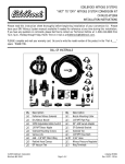
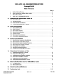
EDELBROCK NITROUS SYSTEMS
“DRY” TO “WET” NITROUS SYSTEM CONVERSION KIT
CATALOG #71883
INSTALLATION INSTRUCTIONS
Please read this instruction sheet thoroughly before beginning installation of your conversion kit. Please
have your DRY Nitrous System manual available if needed for reference at any time during this installation.
If you have any questions or comments, please feel free to contact our Technical Hotline at: 1-800-416-8628 from
7a.m.-5p.m., Monday through Friday, Pacific Time or e-mail us at [email protected].
BILL OF MATERIALS
Qty.
❑1
❑1
❑2
❑1
❑4
❑5
©2005 Edelbrock Corporation
Brochure #63-0399
Description
Performer Fuel Solenoid
E1 Nitrous Nozzle
4AN to 1/8”NPT Fuel Fitting
3AN to 1/8”NPT Fuel Fitting
Solenoid Mounting Screws
Various Jets
Page 1 of 4
Qty.
❑1
❑1
❑1
❑2
❑1
Description
Nozzle Mounting Collar
3AN 90° 15” Blue Line
3AN 90° 15” Red Line
Solenoid Bracket
4AN Red 18” Line
Catalog #71883
Rev. 05/05
INSTALLATION INSTRUCTIONS
This concludes the removal and disassembly of the dry
nitrous system. From this point on, we will be installing
components for the wet nitrous system. This includes
using both the new components that are supplied with this
kit, as well as re-using certain components that were
supplied with your dry nitrous system such as one of the
nitrous solenoids and the dry nitrous system wiring
harness.
WARNING!!!
Before performing any of these steps, turn off
the bottle valve and purge the nitrous system of
pressure. Failure to do so may cause engine
damage and/or personal injury.
DRY COMPONENTS REMOVAL
1. Remove the 3AN nitrous line currently installed
leading from the second nitrous solenoid to the dry
nitrous nozzle.
2. Remove the dry nitrous nozzle and installed jet from
the nozzle collar. Leave the nozzle collar in place for
the time being. Later on during the installation, we
will determine if the dry nozzles mounting location
will be suitable for the E1 nozzle mounting location
or if this will have to be re-located.
3. Disconnect the 4AN feed line from the nitrous
solenoids. Leave the line in place since this line will
be used for the wet system as well.
4. Disconnect the positive solenoid wires from the blue
wire coming from the relay wiring harness.
5. Disconnect the ground wire from the first solenoid.
Make sure that you do not damage the ring terminal
because this ground will be re-used when the
solenoid is re-installed.
6. Disconnect the ground wire from the second
solenoid leading to the fuel pressure safety switch.
7. Remove the fuel pressure safety switch.
8. Using Teflon Paste, install one of the supplied red
4AN to 1/8”NPT fittings into the port where the fuel
pressure safety switch used to be mounted.
9. Disconnect the vacuum lines that were installed for
the dry nitrous system installation and return the
vacuum routing to the fuel pressure regulator back
to the factory configuration.
10. Remove the nitrous solenoid assembly from the
engine compartment.
11. Disassemble the nitrous solenoid assembly
carefully. You will be re-using one of the nitrous
solenoids for your wet nitrous system installation so
take care not to damage the wiring or solenoid body
upon disassembly. You will also re-use the blue 4AN
to 1/8”NPT INLET fitting and the blue 3AN to
1/8”NPT OUTLET fitting, so be careful not to damage
the thread on these fittings when disassembling.
©2005 Edelbrock Corporation
Brochure #63-0399
WET COMPONENTS INSTALLATION
1. Using Teflon Paste, install the supplied red 3AN to
1/8”NPT fitting into the OUTLET of the Performer Fuel
Solenoid.
2. Using Teflon Paste, install the remaining red 4AN to
1/8”NPT fitting supplied with this kit into the INLET of
the Performer Fuel Solenoid.
3. Mount one of the new solenoid brackets supplied in
this kit to the bottom of the Performer Fuel Solenoid
using two of the supplied solenoid mounting screws.
4. Select which Performer Nitrous Solenoid you are going
to re-use. Using Teflon Paste, install the blue 4AN to
1/8”NPT fitting into the INLET side of the Performer
Nitrous Solenoid.
5. Using Teflon Paste, install the blue 3AN to 1/8”NPT
fitting into the OUTLET side of the Performer Nitrous
Solenoid.
6. Mount the remaining supplied solenoid bracket to the
bottom of the Performer Nitrous Solenoid using the
remaining two solenoid mounting screws.
7. Remove the intake boot to allow easy access to the
nozzle collar.
8. Verify the location of the nozzle collar. Make sure that
it is in a location where it has a fairly straight,
unobstructed shot into the manifolds plenum. Also,
make sure that the nozzle is located AFTER the MAF
sensor in the intake boot, if equipped. If the dry nozzle
collar is located in a good place, remove the dry
nozzle, dry nozzle collar and nut, and replace with the
supplied E1 nozzle mounting collar and nut. You will
need to enlarge the mounting hole in the intake boot
to allow the E2 collar to reach through the intake boot.
If the dry nozzle collar is located in a bad location,
such as before the MAF sensor, in the airbox, or far
upstream in the boot, use a 1/16” plug to fill the hole
and drill a new hole for the location of the E1 nozzle
collar and nut.
Page 2 of 4
Catalog #71883
Rev. 05/05 - DC/mc
9. Using Teflon Paste, install the E1 nozzle into the
nozzle collar in the intake boot. Be sure that the
outlet tip of the nozzle is facing into the intake
manifold. If the nozzle is mounted crooked or facing
the wall of the intake boot, fuel and nitrous will be
spraying directly against the wall of the boot, leading
to possible fuel puddling and potential for an intake
backfire.
10. Find a secure location to mount the Performer
Nitrous Solenoid within reach of the nitrous feed line
and the E2 nitrous nozzle using the blue 15” 90°
line. Make sure that this location is away from
moving objects and will not interfere with closure of
the hood.
11. Connect the nitrous feed line to the INLET fitting of
the Performer Nitrous Solenoid. DO NOT use any
thread sealant, since AN fittings are designed as
dry seal fittings.
12. Using the supplied blue 3AN 90° line, connect one
end of the line to the OUTLET fitting on the
Performer Nitrous Solenoid.
13. Using the jet map found at the end of this manual,
select which nitrous and fuel jet you will be using.
It is suggested that you start with the smallest
horsepower gain and build up to ensure proper
system operation.
14. Place the nitrous jet in the fitting labeled “N” on the
E1 nozzle. Attached the free end of the blue 3AN
90° line to this fitting with the jet in place. DO NOT
use any type of thread sealant for this
connection.
15. Find a secure location to mount the Performer Fuel
Solenoid within reach of the red 4AN fuel fitting
mounted in place of the schrader valve using the
supplied 18” 4AN red line and the E2 nitrous nozzle
using the red 15” 90° line. Make sure that this
location is away from moving objects and will not
interfere with closure of the hood.
16. Connect one end of the supplied 18” 4AN red line to
the INLET fitting of the Performer Fuel Solenoid. DO
NOT use any type of thread sealant.
17. Connect the remaining end of the 18” 4AN red line
to the 4AN fitting you installed earlier in the test port
of the fuel rail. DO NOT use any type of thread
sealant.
18. Using the supplied red 3AN 90° line, connect one
end to the OUTLET fitting on the Performer Fuel
Solenoid. DO NOT use any type of thread
sealant.
©2005 Edelbrock Corporation
Brochure #63-0399
19. Place the fuel jet in the fitting labeled “F” in the E2
nozzle. Attach the free end of the red 3AN 90° line to
this fitting with the jet in place. DO NOT use any
type of thread sealant.
This concludes the installation of the hardware for your
Wet Nitrous System. After performing these steps, it is
time to do a pressure check on all of the components that
you just installed before completing the system wiring:
1. You should check the fuel system. Start the engine.
With the engine running, inspect all of the fuel lines
and fittings that you just installed for fuel leaks. If
leaks are apparent, tighten these fittings until the
leaks seal. Also, listen to the sound of the engine. If
the engine starts to bog down, you may have a leak in
the solenoid. If this occurs, call our Edelbrock
Technical Helpline at 1-800-416-8628.
2. You should check the nitrous system. This should be
checked with the engine OFF. Make sure that all
fittings are tight. Slowly open the bottle valve and
walk back around to the engine compartment. Listen
carefully for leaks. Leaks can be noticed by a slight
hissing sound or by ice forming around fittings. You
should hear no sounds coming from fittings or lines if
everything is connected properly. If leaks are noticed,
tighten the fittings until the leaks seal.
FINAL WIRING
1. Connect one wire from each solenoid to the BLUE wire
routed from the relay wiring harness.
2. Ground each remaining wire from the solenoids.
Page 3 of 4
Performer
Fuel
Solenoid
Performer
Nitrous
Solenoid
To BLUE
wire from
harness
Ground
Catalog #71883
Rev. 05/05 - DC/mc
To test the wiring of your Performer Nitrous and
Performer Fuel Solenoids, make sure that the bottle
valve is in the “OFF” position. Turn the ignition key to the
“ACC.” position. With the arming switch in the “ON”
position, quickly tap the microswitch button to activate
the system. You should hear both solenoids “click” is
wired correctly. Make sure that you perform this test
with the valve OFF to prevent filling the manifold with
Nitrous Oxide.
JET MAP INFORMATION
Edelbrock Engineering has conducted extensive dyno
testing with the Edelbrock Universal Single E1 Nozzle
Wet Nitrous System on various vehicles to ensure the
horsepower increase with the nitrous system is safe and
functions as intended. On a typically stock 1.5L to 2.0L,
you can expect the following approximate horsepower
gains:
Nitrous Jetting
.026
.028
.030
Fuel Jetting
.024
.025
.026
Approx. HP Gains
40hp
60hp
80hp
NOTE: This jet map is intended to be used on a
vehicle running approximately 40 psi fuel
pressure.
On an engine of greater displacement, horsepower gains
may be slightly different.
ENGINE OPERATIONS CONSIDERATIONS:
When used correctly, nitrous oxide safely elevates cylinder
pressures and temperatures while increasing combustion
rate. These characteristics make the engine more
sensitive to detonation. To ensure proper performance,
engine and drive line life, the following tips are suggested:
System Jetting
Never exceed the recommended jetting! Excessive jetting
can result in sever engine damage.
Fuel Quality
Because Nitrous Oxide is an oxidizer, fuel selection is
critical. Both octane and fuel consistency affect fuel burn
rate. The oxidizer quality of Nitrous Oxide will accelerate
the burn rate, so we recommend a high quality of gasoline.
We also recommend you use the same grade of gasoline
every time you use your Nitrous Oxide system. This will
help to maintain the same fuel burn rate every time.
Ignition Components
Most aftermarket performance chips increase the vehicle’s
ignition timing, which can cause detonation with the use of
Nitrous Oxide. Please consult with your chip manufacturer
on information regarding the compatibility of your chip
with Nitrous Oxide use. Many power programmers
function using the same method. Contact your power
programmer manufacturer concerning the use of Nitrous
Oxide as well. Many power programmer manufacturers
have specific programs for Nitrous Oxide use.
If your vehicle is equipped with platinum type spark plugs,
we highly recommend they be removed and replaced with
the equivalent stardard-type spark plug.
Engine System Upgrades
With all performance modifications, complementary
system upgrades will always serve to elevate the
consistency and longevity of an engine, especially when
using Nitrous Oxide as a power adder. Modifications such
as ignition upgrades, free-flowing exhaust, camshafts,
cylinder heads, and manifolds can all add to the
performance of a Nitrous Oxide injected engine.
Edelbrock Corporation • 2700 California St. • Torrance, CA 90503
Tech-Line: 800-416-8628 • E-Mail: [email protected]
©2005 Edelbrock Corporation
Brochure #63-0399
Page 4 of 4
Catalog #71883
Rev. 05/05 - DC/mc