1
Ground Bond Tester
GCT-9040
USER MANUAL
GW INSTEK PART NO. 82CT-90400E01
ISO-9001 CERTIFIED MANUFACTURER
This manual contains proprietary information, which is protected by
copyright. All rights are reserved. No part of this manual may be
photocopied, reproduced or translated to another language without
prior written consent of Good Will company.
The information in this manual was correct at the time of printing.
However, Good Will continues to improve products and reserves the
rights to change specification, equipment, and maintenance
procedures at any time without notice.
Good Will Instrument Co., Ltd.
No. 7-1, Jhongsing Rd., Tucheng Dist., New Taipei City 236, Taiwan.
Table of Contents
Table of Contents
SAFETY INSTRUCTIONS ................................................... 5
GETTING STARTED ........................................................... 9
GCT-9040 Overview ............................. 10
Appearance .......................................... 14
Set Up .................................................. 19
OPERATION .................................................................... 25
Menu Tree ............................................ 26
Test Lead Connection ........................... 30
GB Manual Testing .............................. 36
Linked ACW/DCW/IR Tests .................. 57
Common Utility Settings ...................... 66
EXTERNAL CONTROL ..................................................... 74
External Control Overview .................... 75
REMOTE CONTROL ........................................................ 81
Interface Configuration ........................ 82
Command Syntax ................................. 86
Command List for GCT-9040 ................ 89
Error Messages .................................. 124
FAQ ............................................................................... 125
APPENDIX ..................................................................... 127
Fuse Replacement .............................. 127
Error Messages .................................. 128
GCT-9040 Specifications .................... 130
GCT-9040 Dimensions ....................... 131
Declaration of Conformity .................. 133
3
GCT-9040 User Manual
INDEX ............................................................................ 134
4
SAFETY INSTRUCTIONS
SAFETY INSTRUCTIONS
This chapter contains important safety
instructions that you must follow during
operation and storage. Read the following before
any operation to ensure your safety and to keep
the instrument in the best possible condition.
Safety Symbols
These safety symbols may appear in this manual or on the
instrument.
WARNING
Warning: Identifies conditions or practices that
could result in injury or loss of life.
CAUTION
Caution: Identifies conditions or practices that
could result in damage to the instrument or to
other properties.
Attention Refer to the Manual
Protective Conductor Terminal
Frame or Chassis Terminal
Earth (ground) Terminal
5
GCT-9040 User Manual
Do not dispose electronic equipment as unsorted
municipal waste. Please use a separate collection
facility or contact the supplier from which this
instrument was purchased.
Safety Guidelines
General
Guideline
CAUTION
Do not place any heavy object on the
instrument.
Avoid severe impact or rough handling that
leads to damaging the instrument.
Do not discharge static electricity to the
instrument.
Use only mating connectors, not bare wires, for
the terminals.
Do not block the cooling fan opening.
Do not disassemble the GCT-9040 unless you
are qualified.
(Measurement categories) EN 61010-1:2010 specifies the
measurement categories and their requirements as follows. The
GCT-9040 does not fall under category II, III or IV.
Measurement category IV is for measurement performed at the
source of low-voltage installation.
Measurement category III is for measurement performed in the
building installation.
Measurement category II is for measurement performed on the
circuits directly connected to the low voltage installation.
Power Supply
WARNING
6
AC Input voltage range:
100/120/220/230VAC ±10%
Frequency: 50Hz/60Hz
To avoid electrical shock connect the protective
grounding conductor of the AC power cord to
an earth ground.
SAFETY INSTRUCTIONS
Cleaning the
GCT-9040
Operation
Environment
Disconnect the power cord before cleaning.
Use a soft cloth dampened in a solution of mild
detergent and water. Do not spray any liquid.
Do not use chemicals containing harsh material
such as benzene, toluene, xylene, and acetone.
Location: Indoor, no direct sunlight, dust free,
almost non-conductive pollution (Note below)
Relative Humidity: ≤ 70% (no condensation)
Altitude: < 2000m
Temperature: 0˚C~40˚C
(Pollution Degree) EN 61010-1:2010 specifies the pollution degrees
and their requirements as follows. The GCT-9040 falls under degree
2.
Pollution refers to “addition of foreign matter, solid, liquid, or
gaseous (ionized gases), that may produce a reduction of dielectric
strength or surface resistivity”.
Pollution degree 1: No pollution or only dry, non-conductive
pollution occurs. The pollution has no influence.
Pollution degree 2: Normally only non-conductive pollution
occurs. Occasionally, however, a temporary conductivity caused
by condensation must be expected.
Pollution degree 3: Conductive pollution occurs, or dry, nonconductive pollution occurs which becomes conductive due to
condensation which is expected. In such conditions, equipment
is normally protected against exposure to direct sunlight,
precipitation, and full wind pressure, but neither temperature
nor humidity is controlled.
Storage
environment
Disposal
Location: Indoor
Temperature: -10°C to 70°C
Relative Humidity: ≤ 85% (no condensation)
Do not dispose this instrument as unsorted
municipal waste. Please use a separate collection
facility or contact the supplier from which this
instrument was purchased. Please make sure
discarded electrical waste is properly recycled to
reduce environmental impact.
7
GCT-9040 User Manual
Power cord for the United Kingdom
When using the tester in the United Kingdom, make sure the power
cord meets the following safety instructions.
NOTE: This lead/appliance must only be wired by competent persons
WARNING: THIS APPLIANCE MUST BE EARTHED
IMPORTANT: The wires in this lead are coloured in accordance with the
following code:
Green/ Yellow:
Earth
Blue:
Neutral
Brown:
Live (Phase)
As the colours of the wires in main leads may not correspond with
the coloured marking identified in your plug/appliance, proceed
as follows:
The wire which is coloured Green & Yellow must be connected to
the Earth terminal marked with either the letter E, the earth symbol
or coloured Green/Green & Yellow.
The wire which is coloured Blue must be connected to the terminal
which is marked with the letter N or coloured Blue or Black.
The wire which is coloured Brown must be connected to the
terminal marked with the letter L or P or coloured Brown or Red.
If in doubt, consult the instructions provided with the equipment
or contact the supplier.
This cable/appliance should be protected by a suitably rated and
approved HBC mains fuse: refer to the rating information on the
equipment and/or user instructions for details. As a guide, a cable
of 0.75mm2 should be protected by a 3A or 5A fuse. Larger
conductors would normally require 13A types, depending on the
connection method used.
Any exposed wiring from a cable, plug or connection that is
engaged in a live socket is extremely hazardous. If a cable or plug is
deemed hazardous, turn off the mains power and remove the cable,
any fuses and fuse assemblies. All hazardous wiring must be
immediately destroyed and replaced in accordance to the above
standard.
8
GETTING STARTED
GETTING STARTED
This chapter describes the safety tester in a
nutshell, including its main features and front /
rear panel introduction. After going through the
overview, please read the safety considerations in
the Set Up chapter.
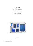
GCT-9040
Ground Bond Tester
PASS
FAIL
ESC
PAGE
READY
TEST
CAUTION
40A MAX.
START
POWER
STOP
REMOTE
SENSE H
MANU
EDIT/SAVE
UTILITY
SOURCE H
GB Rx
SENSE L
SOURCE L
GCT-9040 Overview ......................................................... 10
Introduction to the GCT-9040 ................................................................ 10
Main Features .......................................................................................... 11
Accessories ............................................................................................... 11
Package Contents .................................................................................... 13
Appearance ..................................................................... 14
Front Panel ............................................................................................... 14
Rear Panel ................................................................................................. 17
Set Up ............................................................................. 19
Line Voltage Connection and Power Up ............................................. 19
Installing the Optional GPIB Card ........................................................ 21
Workplace Precautions ........................................................................... 22
Operating Precautions ............................................................................ 23
9
GCT-9040 User Manual
GCT-9040 Overview
Introduction to the GCT-9040
GCT-9040 is a ground bond tester that can operate as a standalone
unit or in conjunction with a GPT-9000 Series safety tester to
perform additional ACW/DCW/IR tests before, after or
simultaneously(ACW/DCW only) with GB tests.
When the GCT-9040 operates with a GPT-9000 Series safety tester,
it uses a dedicated LINK port and remote commands to
communicate in a master-slave fashion. The GCT-9040 operates as
the master and the GPT-9000 Series unit operates as a slave.
The GCT-9040 can store up to 100 manual tests allowing the safety
testers to accommodate any number of safety standards, including
IEC, EN, UL, CSA, GB, JIS and others.
Note: Throughout this user manual, the terms ACW, DCW, IR and
GB refer to AC Withstanding, DC Withstanding, Insulation
Resistance and Ground Bond testing, respectively. GPT-9000 refers
to any of the GPT-98XX or GPT-99XX models, GPT-9000A refers to
any of the GPT-99XXA models. For information specific to the GPT9000, please see the GW Instek website, http://www.gwinstek.com.
10
GETTING STARTED
Main Features
Performance
GB: 3A~40A ac
Features
100 test conditions (MANU mode)
Over temperature, voltage and current
protection
Pass, Fail, Test, Caution and Ready indicators
PWM output (90% efficiency, increased
reliability)
Interlock (configurable).
Remote control start/stop interface terminal
USB interface for programming
Optional GPIB interface for programming
Signal I/O port for pass/fail/test monitoring
and start/stop control/interlock
LINK port to control slave units for ACW, DCW
and IR tests.
Interface
Accessories
Standard
Accessories
Part number
Description
Region dependent
Power cord
GTL-215 x1
GB Test leads
N/A
Remote terminal male plug
N/A
Interlock key
GTL-247
Type A-A USB cable
GTL-132
Link cable
11
GCT-9040 User Manual
Optional
Accessories
Options
12
Part number
Description
GTL-248
GPIB cable
GTL-251
GPIB-USB-HS (high speed)
GRA-417
Rack Adapter Panel (19”, 4U)
Part number
Description
Opt.01 GPIB Interface
GPIB card
GETTING STARTED
Package Contents
Check the contents before using the GCT-9040.
Opening the box
Contents
(single unit)
GCT-9040 unit
Quick Start guide
Note
Power cord x1 (region
dependent)
User manual CD
GTL-215 test leads x1
CTC (Calibration
Traceable Certificate)
GTL-132 LINK cable
Remote terminal male
plug
Interlock key
Type A-A USB cable
Keep the packaging, including the box, polystyrene
foam and plastic envelopes should the need arise
to return the unit to GW Instek.
13
GCT-9040 User Manual
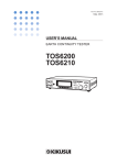
Appearance
Front Panel
PASS/FAIL indicators
Function keys
Directional keys
Display
GCT-9040
Ground Bond Tester
PASS
FAIL
ESC
PAGE
READY
READY indicator
TEST
CAUTION
40A MAX.
START
POWER
button
STOP
REMOTE
POWER
SENSE H
MANU
EDIT/SAVE
UTILITY
SOURCE H
GB Rx
SENSE L
TEST indicator
CAUTION
indicator
Sense H and L
terminals
SOURCE L
Source H and L
terminals
START button
REMOTE terminal
Scroll wheel
STOP button
Configuration keys
Display
240 X 64 dot matrix display (LCD)
Function keys
The function keys correspond to the soft-keys
directly above on the main display.
Pass/Fail
indicators
PASS
ESC key
ESC
PAGE key
Directional arrow
keys
14
PAGE
FAIL
The PASS and FAIL indicators
light up upon a PASS or FAIL test
result at the end of a manual test
or automatic test.
The ESC key is used to exit out of
a menu or cancel a setting.
The PAGE key is used in the EDIT
status to toggle the HI/LO setting
between mΩ & V.
The directional arrow keys are
used to navigate menus and
parameter settings.
GETTING STARTED
READY indicator
TEST indicator
CAUTION
indicator
The READY indicator is lit when
the tester is ready to begin testing.
The STOP button is used to put
the tester into READY status.
READY
The TEST indicator is lit when a
test is on. The START button is
used to put the tester into TEST
status.
TEST
The CAUTION indicator will light
up when the output terminals are
active. Only after the test has
finished or stopped will the
indicator turn off.
PAGE
CAUTION
40A MAX.
SENSE and
SOURCE
terminals
SENSE H
GB Rx
SOURCE H
The scroll wheel is used to edit
parameter values.
Scroll wheel
UTILITY key
EDIT/SAVE key
MANU key
SENSE L
SOURCE L
The SOURCE H, SOURCE L,
SENSE H and SENSE L
terminals are used for GB
testing.
UTILITY
Used to enter the Common Utility
menu.
EDIT/SAVE
Used to start editing MANU tests
as well as save settings and
parameters.
MANU
The MANU key is used to select
manual tests.
15
GCT-9040 User Manual
REMOTE
terminal
STOP button
START button
REMOTE
STOP
START
The REMOTE terminal is used to
connect to a remote controller.
The STOP button is used to
stop/cancel tests. The STOP
button will also put the tester in
the READY status to begin testing.
The START button is used to start
tests.
The START button can be used to
start tests when the tester is in the
READY status. Pressing the
START button will put the tester
in the TEST status.
POWER switch
16
POWER
Turns the power on. The tester
will always start up with the last
test setting from when the
instrument was last powered
down.
GETTING STARTED
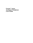
Rear Panel
SIGNAL I/O USB A port
LINK port
Fan
GND
WARNING
SIGNAL I / O
TO AVOID ELECTRIC SHOCK THE POWER CORD
PROTECTIVE GROUNDING CONDUCTOR MUST BE
CONNECTED TO GROUND.
FOR CONTINUED FIRE PROTECTION. REPLACE
ONLY WITH SPECIFIED TYPE AND RATED FUSE.
NO OPERATOR SERVICEABLE COMPONENTS INSIDE.
DO NOT REMOVE COVERS. REFER SERVICING TO
QUALIFIED PERSONNEL.
LINK
GND
GPIB
ENSURE THE POWER IS REMOVED FROM
THE INSTRUMENT BEFORE REPLACING THE FUSE
AC
POWER MAX.
700VA
LINEVOLTAGE RANGE
SELECTION (50/60Hz)
SER. NO. LB
Optional GPIB port
SIGNAL I/O port
SIGNAL I / O
LINK
198-242V
207-250V
Line voltage
FUSE
T 7A
250V
T 4A
250V
Fuse selector
The SIGNAL I/O port is used to
monitor the tester status (PASS,
FAIL, TEST) and input (START/
STOP signals). It is also used with
the Interlock key.
With the GCT-9040 acting as the
master unit, the LINK port is used
to control a GPT-9XXX slave unit to
perform additional ACW, DCW or
IR tests.
Exhaust fan. Allow enough room
for the fan to vent. Do not block the
fan openings.
Fan/Fan Vents
GND
90-110V
108-132V
220V
230V
Used for remote control and
firmware updates.
USB A port
LINK port
100V
120V
GND
Connect the GND (ground)
terminal to the earth ground.
17
GCT-9040 User Manual
120
220
230
Line voltage input
100
220
230
120
Line voltage fuse
100
Optional GPIB
port
18
GPIB
Line voltage input:
100/120/220/230VAC ±10%
Line voltage selector and fuse:
100V/120V
T7A 250V
220V/230V
T4A 250V
Optional GPIB interface for remote
control.
GETTING STARTED
Set Up
Line Voltage Connection and Power Up
Background
Steps
Before powering up the GCT-9040 ensure the
correct voltage has been selected on the rear
panel. The GCT-9040 supports line voltages of
100V/120V/220V and 230V.
1. Check the line voltage and the fuse Page 127
in the fuse holder.
The desired line voltage
should line up with the
arrow on the fuse holder.
120
100
120
100
Warning
220
230
3. If the power cord does not
have an earth ground,
ensure the ground
terminal is connected to an
earth ground.
230
2. Connect the power cord to
the AC voltage input.
220
GND
Ensure the power cord is connected to an earth
ground. Failure could be harmful to the operator
and instrument.
4. Press the Power button.
POWER
19
GCT-9040 User Manual
5. When the unit is powering up, all the LED
indicators will light. Check to make sure all 5
LED indicators are working.
6. Check to make sure the System Self Test passes
without errors.
S Y S T EM S E L F
TEST
S y s t em Ch e c k i n g . . .
Ha r dwa r e Che c k i ng . . .
F i r mw a r e C h e c k i n g . . .
After the System Self Test completes, the tester will
go into VIEW status and be ready to operate.
VIEW status
MANU = * * * - 0 0 2
MA NU _ N AME
FREQ= 6 0 H z
H I =0 . 800V
10 00
A
GBR =
mΩ R A M P
G-W
F CON T L I NK
WARNING
20
V
=000 . 1S
GB
REF # = 0 . 0 0 0 V
LO= 0 . 0 0 0V
V I EW
T I ME R = 0 0 1 . 0 S
See the Appendix on page 128 for details if a selftest error is detected.
GETTING STARTED
Installing the Optional GPIB Card
Background
WARNING
Steps
The optional GPIB is a user-installable option.
Follow the instructions below to install the
GPIB card.
Before installing the optional GPIB card ensure the
GCT-9040 is turned off and disconnected from
power.
1. Remove the screws from the rear panel cover
plate.
2. Insert the GPIB card into the two slots on either
side of the opening. Push the card gently until it
is fully inserted.
21
GCT-9040 User Manual
Workplace Precautions
Background
WARNING
The GCT-9040 is a high current instrument that
is capable of delivering up to 40A. The
following section describes precautions and
procedures that must be followed to ensure a
safe work environment.
The GCT-9040 generates high current in excess of
40A. Follow all safety precautions, warnings and
directions given in the following section when
using the instrument.
1. Only technically qualified personnel should be
allowed to operate the tester.
2. The operating workplace must be fully isolated,
especially when the instrument is in operation.
The instrument should be clearly labeled with
appropriate warning signage.
3. The operator should not wear any conductive
materials, jewelry, badges, or other items, such
wrist watches.
4. The operator should wear insulation gloves for
electrical protection.
5. Ensure the earth ground of the line voltage is
properly grounded.
6. When high current flows through the test leads
a strong magnetic field is produced. Ensure any
devices that are adversely affected by magnetic
fields are not placed near the tester.
22
GETTING STARTED
Operating Precautions
Background
WARNING
The GCT-9040 is a high current instrument. The
following section describes precautions and
procedures that must be followed to ensure that
the tester is operated in a safe manner.
The GCT-9040 generates outputs up to 40A ac.
Follow all safety precautions, warnings and
directions given in the following section when
using the instrument.
1. Never touch the tester, lead wires, terminals,
probes and other connected equipment when
the tester is testing.
2. After testing, any probes, terminals or ports
may become extremely hot due to the high test
current. Do not touch these points to avoid
burns.
3. Do not turn the tester on and off quickly or
repeatedly. When turning the power off, please
allow a few moments before turning the power
back on. This will allow the protection circuits
to properly initialize.
Do not turn the power off when a test is
running, unless in an emergency.
4. Only use those test leads supplied with the
instrument. Leads with inappropriate gauges
can be dangerous to both the operator and the
instrument.
Never use the Sense leads on the SOURCE
terminals.
23
GCT-9040 User Manual
5. Ensure the earth ground of the line voltage is
properly grounded.
6. Only connect the test leads to the SOURCE
H/SENSE H terminals before the start of a test.
Keep the test leads disconnected at all other
times.
7. Always press the STOP button when pausing
testing.
8. Do not leave the tester unattended. Always
turn the power off when leaving the testing
area.
9. When remotely controlling the tester, ensure
adequate safety measures are in place to
prevent:
24
Inadvertent output of the test current.
Accidental contact with the instrument during
testing. Ensure that the instrument and DUT are
fully isolated when the instrument is remotely
controlled.
OPERATION
OPERATION
Menu Tree ....................................................................... 26
Menu Tree Overview .............................................................................. 27
Test Lead Connection ...................................................... 30
GB Connection ......................................................................................... 30
Grounding Mode Note ........................................................................... 33
GB Manual Testing .......................................................... 36
Choose/Recall a Manual Test Number ................................................ 37
Edit Manual Test Settings ...................................................................... 38
Setting the GB Test Current ................................................................... 39
Setting the Test Frequency ..................................................................... 39
Setting the Upper and Lower Limits .................................................... 40
Setting a Reference Value ....................................................................... 42
Setting the Test Time (Timer) ................................................................ 43
Creating a MANU Test File Name ........................................................ 44
Saving and Exiting EDIT Status ............................................................ 45
Running a MANU Test ........................................................................... 47
PASS / FAIL MANU Test ...................................................................... 51
Zeroing of the Test Leads ....................................................................... 54
Linked ACW/DCW/IR Tests .............................................. 57
LINK Connection .................................................................................... 58
LINK Test Configuration ....................................................................... 60
Run LINK Test ......................................................................................... 63
25
GCT-9040 User Manual
Menu Tree
This section describes the overall structure of the operation statuses
and modes for the GCT-9040 ground bond safety tester. The tester
has one testing mode (MANU mode) and 5 main operation statuses
(VIEW, EDIT, READY, TEST and STOP).
PASS
FA I L
status
status
Press
START
Z E RO
TEST
status
status
Press
START
Short test leads
Press
STOP
Press
ZERO
soft-key
Press
STOP
Press
START
S TOP
status
Press
STOP
READY
Press
STOP
X2
status
Press
MANU
Common Utility
Settings1
Press
STOP
Press
UTILITY
V I EW
status
Press
EDIT/
SAVE
Toggle between
ref/HI/LO V and
ref/HI/LO Ω
Press
PAGE
Press
ESC
ED I T
status
1 Press EDIT/SAVE to save settings, or ESC to cancel and return to the previous screen.
26
Press
EDIT/
SAVE
Save the MANU
test
OPERATION
Menu Tree Overview
VIEW status
VIEW status is used to view the parameters of
the selected manual test. The VIEW status is
also used to select the MANU test number.
VIEW status is the default state of the unit.
VIEW status
MANU = * * * - 0 0 2
MA NU _ N AME
FREQ= 6 0 H z
H I =0 . 800V
10 00
A
GBR =
mΩ R A M P
G-W
F CON T L I NK
EDIT status
REF # = 0 . 0 0 0 V
LO= 0 . 0 0 0V
V
=000 . 1S
GB
V I EW
T I ME R = 0 0 1 . 0 S
EDIT status is used to edit the manual test
parameters. Pressing the EDIT/SAVE key will
save any changes. Pressing the ESC key will
cancel any changes.
EDIT status
MANU = * * * - 0 0 2
MANU _ NAME
FREQ= 6 0 H z
H I =0 . 800V
10 00
A
GBV = 0 . 8 0 0 V
G-W
F CON T L I NK
READY status
REF # = 0 . 0 0 0 V
LO= 0 . 0 0 0V
V
GB
ED I T
T I ME R = 0 0 1 . 0 S
H I / L O T I MER
When the tester is in READY status, it is ready
to begin testing. Pressing the START button
will begin testing and put the tester into TEST
status. Pressing the MANU key will return the
tester to VIEW status.
READY status
MANU = * * * - 0 0 2
MA NU _ N AME
FREQ= 6 0 H z
H I =0 . 800V
10 00
A
GBR =
mΩ R A M P
G-W
F CON T L I NK
V
=000 . 1S
GB
REF # = 0 . 0 0 0 V
LO= 0 . 0 0 0V
READY
T I ME R = 0 0 1 . 0 S
Z ERO
27
GCT-9040 User Manual
TEST status
TEST status is active when a MANU test is
running. Pressing STOP will cancel the test.
TEST status
MANU = * * * - 0 0 2
FREQ= 6 0 H z
MA NU _ N AME
H I =0 . 800V
10 00 0 051
A
G B R = 0 0 5 . 1 mΩ R A M P
G-W
F CON T L I NK
STOP status
V
=000 . 1S
GB
MA NU _ N AME
H I =0 . 800V
10 00 0 051
A
G B R = 0 0 5 . 1 mΩ R A M P
G-W
F CON T L I NK
V
=000 . 1S
GB
MA NU _ N AME
H I =0 . 800V
10 00 0 051
A
G B R = 0 0 5 . 1 mΩ R A M P
G-W
F CON T L I NK
V
=000 . 1S
GB
S TOP
T I ME R = 0 0 1 . 0 S
REF # = 0 0 0 . 0 V
LO= 0 . 0 0 0V
Z E RO
T I ME R = 0 0 1 . 0 S
Z ERO
When in the VIEW mode, you can select a
MANU test number with the scroll wheel.
MANU test number
MANU = * * * - 0 0 2
MA NU _ N AME
FREQ= 6 0 H z
H I =0 . 800V
10 00
A
GBR =
mΩ R A M P
G-W
F CON T L I NK
28
REF # = 0 . 0 0 0 V
LO= 0 . 0 0 0V
ZERO status is shown when performing a
zeroing test for the test leads. Performing a
zeroing test will automatically set the REF#
value for the selected test.
ZERO status
MANU = * * * - 0 0 2
FREQ= 6 0 H z
MANU test
number
TEST
T I ME R = 0 0 1 . 0 S
Z ERO
STOP status is shown when a manual test did
not finish running and has been stopped by the
operator. Pressing STOP will return the tester to
READY status.
STOP status
MANU = * * * - 0 0 2
FREQ= 6 0 H z
ZERO status
REF # = 0 . 0 0 0 V
LO= 0 . 0 0 0V
V
=000 . 1S
GB
REF # = 0 . 0 0 0 V
LO= 0 . 0 0 0V
V I EW
T I ME R = 0 0 1 . 0 S
OPERATION
Common Utility
Settings
This utility controls the LCD, buzzer, interface,
control and time settings. These settings are
system wide.
C O MMO N U T I L I T Y
L CD
L CD
L CD
Con t r a s t : 8
B r i g h t n e s s : BR I GH T
BUZ Z
I NTER
CTRL
CTRL
T I ME
29
GCT-9040 User Manual
Test Lead Connection
This section describes how to connect the GCT-9040 to a DUT for
ground bond testing. The DUT should be floating with respect to
ground and should be powered off.
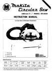
GB Connection
Background
Single GB
Connection
GB tests use the SENSE H/L and SOURCE H/L
terminals with the GTL-215 test leads.
GPT-9000
Source H
Sense H
Source L
Sense L
DUT
FLOATING
Ground bond tests are usually connected
between the ground pin (conductor terminal) of
the DUT’s power cord or power socket and a
conductive point on the DUT chassis.
ACW/DCW/IR
and GB
Connection
GPT-9XXX (ACW/DCW)
DUT
FLOATING
GCT-9XXX (GB tests)
High Voltage terminal
Source H
Sense H
Return terminal
Sense L
Source L
ACW, DCW and IR withstanding tests are
usually performed by testing the withstanding
potential (ACW/DCW) or resistance (IR) from
the neutral or live pin and the ground pin
(conductor terminal) of the DUT.
30
OPERATION
1. Turn the power off on the safety tester.
Steps for GB
Connection
(GCT-9040)
2. Using the GTL-215 GB test lead,
a.
Connect the Sense H lead to the SENSE
H terminal.
b. Connect the Sense L lead to the SENSE
L terminal.
c.
Connect the Source H lead to the
SOURCE H terminal.
d. Connect the Source L lead to the
SOURCE L terminal.
Sense H lead
Sense L lead
SENSE H
Source H lead
GB Rx
SOURCE H
SENSE L
Source L lead
SOURCE L
e.
Connect the H clip of the GB test lead
to a conductive point on the DUT
chassis.
f.
Connect L clip of the GB test lead to the
ground (conductor terminal) pin of the
DUT power cord or power socket.
Ground pin from power cord
or power socket
DUT
G
Conductive point
on the chassis
N
H clip
L
L clip
31
GCT-9040 User Manual
Steps for
ACW/DCW/IR
Connection
(GPT-9XXX)
1. Turn the power off on the GPT-9XXX safety
tester.
2. Using the GHT-114 test leads,
a.
Connect the high voltage test lead(red)
to the HIGH VOLTAGE terminal and
screw firmly into place.
b. Connect the return test lead(white) into
the RETURN terminal and screw the
protector bar into place, as shown
below.
HIGH VOLTAGE
Terminal
RETURN
Terminal
c.
Connect the high potential clip to
neutral or live pin of the power cord or
socket of the DUT that you want to test.
d. Connect the return clip to the ground
pin (conductor terminal) of the power
cord or socket.
32
OPERATION
Ground pin from power cord
or power socket
DUT
L clip
G
H clip
N
L
Live or neutral pin from
power cord or socket.
Grounding Mode Note
Background
The GCT-9040 operates with the SOURCE L
terminal floating with respect to the earth
ground. For the GCT-9040 and GPT-9XXX
Series, this is referred to as having the
GROUND MODE is set to OFF. On the GCT9040 this mode is fixed.
When performing additional ACW or DCW
tests, a slave GPT-9XXX Series unit can operate
with the GROUND MODE set to ON or OFF.
33
GCT-9040 User Manual
Overview
GROUND MODE = OFF
This mode is for DUTs that are floating and not
directly connected to an earth ground. When
GROUND MODE is set to OFF any stray
capacitance/resistance that leaks to the earth
ground from the DUT side of the testing circuit
are not measured. GB and IR tests must operate
with GROUND MODE = OFF.
GROUND MODE = ON
When GROUND MODE is set to ON, the GPT9XXX grounds the return terminal to the
ground. This mode measures the potential of
the HIGH VOLTAGE terminal with respect to
earth ground. This means that any stray
capacitance/resistance that leaks to earth
ground will also be measured.
For further details about the grounding mode
for the ACW, DCW and IR tests, please see the
GPT-9XXX user manual.
The ground mode icons represent the ground
mode settings.
Ground Mode
Icons
MA
2 A MANU _ NAME
MANU = * * * - 0 0 2
MANU _ NAME
RN
EU
F =# *= *0 *0 -. 00 00 m
L 0 S E T = 0 1 . 0 0mA
FREQ= 6 0 H z
L 0 S E T = 0 1 . 0 0mA F REQ = 6 0 H z
0 050
A CW
D CW
kV
RAMP
I R
mA
=000 . 1S
GB
I T
0E D050
kV
T I ME R = 0 0 1 . 0 S RAMP
AC
HWI / L O D C
TW
I MER I R
GROUND
MODE = OFF
34
mA
=000 . 1S
GB
RE F # = 0 0 . 0 0mA
ED I T
T I ME R = 0 0 1 . 0 S
H I / L O T I MER
GROUND
MODE = ON
OPERATION
Warning
The GCT-9040 is a floating device. The DUT
ground mode setup depends on the GPT-9XXX
ground mode setting.
GPT-9XXX (ACW/DCW)
GCT-9040 (GB tests)
DUT
High Voltage terminal
Source H
Sense H
Sense L
Return terminal
Source L
1
GROUND MODE =
ON or OFF
GPT-9XXX (ACW/DCW)
GROUND MODE = OFF
GROUNDED DUT
GCT-9040 (GB tests)
DUT
High Voltage terminal
Source H
Sense H
Sense L
Return terminal
Source L
1
GROUND MODE =
ON or OFF
2
DUT FLOATING
2
GROUND MODE = OFF
35
GCT-9040 User Manual
GB Manual Testing
This section describes how to create, edit and run a single GB safety
test. Each Manual setting described in this chapter only applies to the
selected manual test – no other manual tests are affected.
Each manual test can be created/stored/recalled to/from one of
100 memory locations.
Choose/Recall a Manual Test number → from page 37.
Edit Manual Test Settings → from page 38.
Setting the GB Test Current→ from page 39.
Setting the Test Frequency → from page 39.
Setting the Upper and Lower Limits → from page 40.
Setting a Reference Value → from page 42.
Setting the Test Time (Timer) → from page 43.
Creating a MANU Test File Name→ from page 44.
Saving and Exiting EDIT Status→ from page 45.
Running a MANU Test → from page 47.
PASS / FAIL MANU Test → from page 51.
Zeroing of the Test Leads → from page 54
Before operating the GCT-9040 please read the safety precautions
as outlined in the Set Up chapter on page 19.
36
OPERATION
Choose/Recall a Manual Test Number
Background
Steps
Up to 100 different manual tests can be
saved/recalled. MANU tests are selected in the
VIEW status.
1. Ensure that the tester is in VIEW status.
See the menu tree on page 26 for details on how
to enter the VIEW status.
VIEW status
MANU = * * * - 0 0 2
MA NU _ N AME
FREQ= 6 0 H z
H I =0 . 800V
10 00
A
GBR =
mΩ R A M P
G-W
F CON T L I NK
V
=000 . 1S
GB
REF # = 0 . 0 0 0 V
LO= 0 . 0 0 0V
V I EW
T I ME R = 0 0 1 . 0 S
2. Use the scroll wheel to choose the
MANU number.
MANU #
001~100
MANU test number
MANU = * * * - 0 0 2
MA NU _ N AME
FREQ= 6 0 H z
H I =0 . 800V
10 00
A
GBR =
mΩ R A M P
G-W
F CON T L I NK
Note
V
=000 . 1S
GB
REF # = 0 . 0 0 0 V
LO= 0 . 0 0 0V
V I EW
T I ME R = 0 0 1 . 0 S
The MANU number can only be chosen in VIEW
status. If in the EDIT status, switch to the VIEW
status by pressing the EDIT/SAVE or ESC key.
37
GCT-9040 User Manual
Edit Manual Test Settings
Background
To edit any of the manual test settings, the
tester must be in EDIT status.
Any settings or parameters that are edited only
apply to the currently selected MANU number.
Steps
1. Press the EDIT/SAVE key when in
VIEW status to enter the EDIT
status. This will enter the EDIT
status for the currently chosen test
number.
Currently selected
MANU test number
V I EW
MANU = * * * - 0 0 2
MANU _ NAME
FREQ= 6 0 H z
H I =0 . 800V
10 00
A
GBV = 0 . 8 0 0 V
G-W
F CON T L I NK
REF # = 0 . 0 0 0 V
LO= 0 . 0 0 0V
V
GB
EDIT/SAVE
ED I T
T I ME R = 0 0 1 . 0 S
H I / L O T I MER
2. The Status changes from VIEW to EDIT.
Note
38
Pressing the EDIT/SAVE key again will save the
settings for the current test and return back to
VIEW status.
OPERATION
Setting the GB Test Current
Background
Steps
The GB test current can be set from 3A to 40A
ac.
1. Ensure the tester is in EDIT status. Page 38
2. Press the UP / DOWN arrow keys
to bring the cursor to the current
setting.
MANU = * * * - 0 0 2
MANU _ NAME
FREQ= 6 0 H z
H I =0 . 800V
10 00
A
GBV = 0 . 8 0 0 V
G-W
F CON T L I NK
REF # = 0 . 0 0 0 V
LO= 0 . 0 0 0V
V
GB
ED I T
T I ME R = 0 0 1 . 0 S
H I / L O T I MER
cursor
3. Use the scroll wheel to set the
current level.
GB
Note
3.00A ~ 40.00A ac
The ground bond voltage (GBV) is calculated as
the HI limit voltage + REF voltage (or (HI limit Ω +
REFΩ) X test current).
Setting the Test Frequency
Background
Steps
A test frequency of 60Hz or 50Hz can be set,
regardless of the input line voltage.
1. Ensure the tester is in EDIT status. Page 38
39
GCT-9040 User Manual
2. Press the UP / DOWN arrow keys
to bring the cursor to the FREQ
setting.
MANU = * * * - 0 0 2
MANU _ NAME
FREQ= 6 0 H z
H I =0 . 800V
10 00
A
GBV = 0 . 8 0 0 V
G-W
F CON T L I NK
REF # = 0 . 0 0 0 V
LO= 0 . 0 0 0V
V
GB
ED I T
T I ME R = 0 0 1 . 0 S
H I / L O T I MER
cursor
3. Use the scroll wheel to set the test
frequency.
Frequency 50Hz, 60Hz
Setting the Upper and Lower Limits
Background
Steps
There is both a LO and HI judgment setting.
When the measured value is below the LO SET
setting, the test will be judged as FAIL. When
the value exceeds the HI SET setting the test
will be judged as FAIL. Any measurement
between the LO SET and HI SET setting is
judged as PASS. The LO SET limit cannot be
made greater than the HI SET limit.
1. Ensure the tester is in EDIT status. Page 38
2. Press the PAGE to choose the HI
and LO value units (voltage or
resistance).
40
PAGE
OPERATION
Note
Toggling the HI/LO units will also toggle the REF#
units as well (REF# mΩ, REF# V). The REF# units
and the HI/LO units are the same. If the units are
changed, the REF# value will need to be set again.
See page 42 for setting the REF# value.
3. Press the HI/LO soft-key or use
the UP / DOWN arrow keys to
bring the cursor to the HI limit
setting.
H I / LO
OR
4. Use the scroll wheel to set the HI
limit.
HI
000.1mΩ ~ 650.0mΩ
0.001V ~ 7.200V
5. Repeat steps 2 and 3 for the LO limit setting.
LO
Example: V units
000.0mΩ ~ 649.9mΩ
0.000V ~ 7.199V
MANU = * * * - 0 0 2
MANU _ NAME
FREQ= 6 0 H z
H I =0 . 800V
10 00
A
GBV = 0 . 8 0 0 V
G-W
F CON T L I NK
REF # = 0 . 0 0 0 V
LO= 0 . 0 0 0V
V
GB
HI limit
Example: Ω units
10 00
R E F # = 0 2 0 . 0 mΩ
L O = 0 0 0 . 0 mΩ
mΩ
GB
HI limit
Note
LO limit
MANU = * * * - 0 0 2
MANU _ NAME
FREQ= 6 0 H z
H I = 5 0 0 . 0 mΩ
A
GBV = 5 . 0 0 0 V
G-W
F CON T L I NK
ED I T
T I ME R = 0 0 1 . 0 S
H I / L O T I MER
ED I T
T I ME R = 0 0 1 . 0 S
H I / L O T I MER
LO limit
The LO SET setting is limited by the HI SET
setting. The LO SET limit cannot be greater than
the HI SET limit.
41
GCT-9040 User Manual
Setting a Reference Value
Background
Steps
The REF# acts as an offset. The REF# value is
subtracted from the measured current (ACW,
DCW) or measured resistance (IR, GB).
1. Ensure the tester is in EDIT status. Page 38
2. Press the PAGE soft-key to choose
the REF# value unit (voltage or
resistance).
Note
PAGE
Toggling the REF# units will also toggle the HI/LO
units (HI/LO mΩ, HI/LO V). The REF# units and
the HI/LO units are the same. If the units are
changed, the HI/LO settings will need to be set
again. See page 40 for setting the HI/LO values.
3. Press the UP / DOWN arrow keys
to bring the cursor to the
REF# setting.
4. Use the scroll wheel to set the
REF# value.
REF# (Ω)
REF# (V)
000.0mΩ ~ 650.0mΩ
0.000V ~ 7.200V
REF#
Example: V units
MANU = * * * - 0 0 2
MANU _ NAME
FREQ= 6 0 H z
H I =0 . 800V
10 00
A
GBV = 1 . 3 0 0 V
G-W
F CON T L I NK
42
REF # = 0 . 5 0 0 V
LO= 0 . 0 0 0V
V
GB
ED I T
T I ME R = 0 0 1 . 0 S
H I / L O T I MER
OPERATION
Example: Ω units
REF#
MANU = * * * - 0 0 2
MANU _ NAME
FREQ= 6 0 H z
H I = 5 0 0 . 0 mΩ
10 00
A
GBV = 5 . 2 0 0 V
G-W
F CON T L I NK
R E F # = 0 2 0 . 0 mΩ
L O = 0 0 0 . 0 mΩ
mΩ
GB
ED I T
T I ME R = 0 0 1 . 0 S
H I / L O T I MER
Note
Limitations:
((REF# (Ω) + HI Set (Ω) ) x I Set) < 7.2V.
((REF# (V) + HI Set (V)) < 7.2V.
Note
A reference offset can be automatically created
using the zeroing function. See page 54 for details.
Setting the Test Time (Timer)
Background
The TIMER setting is used to set the test time
for the current test. The test time determines
how long the test current is applied to the
DUT. The test time can be set from 0.5 to 999.9
seconds, with a resolution of 0.1 seconds.
Test I
Start I
TEST TIME
time
Initial time
(Approximately 100ms)
Note
Steps
Each test has an initial test time of approximately
100ms. This time cannot be edited.
1. Ensure the tester is in EDIT status. Page 38
43
GCT-9040 User Manual
2. Press the TIMER soft-key or use
the UP/DOWN arrow keys to
bring the cursor to the TIMER
setting.
MANU = * * * - 0 0 2
MANU _ NAME
FREQ= 6 0 H z
H I =0 . 800V
10 00
A
GBV = 0 . 8 0 0 V
G-W
F CON T L I NK
T I MER
OR
REF # = 0 . 0 0 0 V
LO= 0 . 0 0 0V
V
GB
ED I T
T I ME R = 0 0 1 . 0 S
H I / L O T I MER
cursor
3. Use the scroll wheel to set the
TIMER value.
GB
000.5s~999.9s
Creating a MANU Test File Name
Background
Each MANU test can have a user-defined test
file name (default: MANU_NAME) up to 10
characters long. See the character list below for
the allowed characters.
Character List:
01234
ABCDE
ab c de
+ - * / _
Steps
44
5678
FGH I
f gh i
= : Ω?
9
J K L MN O P Q R S T U VWX Y Z
j k l mn o p q r s t u v w x y z
( ) <> [ ]
1. Ensure the tester is in EDIT status. Page 38
OPERATION
2. Use the UP/DOWN arrow keys to
bring the cursor to the MANU test
file name at the top of the screen.
The test file name is initially set as
MANU_NAME.
cursor
MANU = * * * - 0 0 2
MANU _ NAME
FREQ= 6 0 H z
H I =0 . 800V
10 00
A
GBV = 0 . 8 0 0 V
G-W
F CON T L I NK
REF # = 0 . 0 0 0 V
LO= 0 . 0 0 0V
V
GB
ED I T
T I ME R = 0 0 1 . 0 S
H I / L O T I MER
3. Use the scroll wheel to scroll
through the available characters.
4. Press the Left/Right arrow keys to
go the next character.
5. The MANU test file name is set when the
current test setting is saved or when the cursor
is moved to another setting.
Saving and Exiting EDIT Status
Background
Steps
After all test parameters have been set, the test
can be saved.
1. When in EDIT status, press the
EDIT/SAVE key to save the
current test. This will enter the
VIEW status for the chosen test
number.
EDIT/SAVE
45
GCT-9040 User Manual
ED I T
MANU = * * * - 0 0 2
MA NU _ N AME
FREQ= 6 0 H z
H I =0 . 800V
10 00
A
GBR =
mΩ R A M P
G-W
F CON T L I NK
V
=000 . 1S
GB
REF # = 0 . 0 0 0 V
LO= 0 . 0 0 0V
V I EW
T I ME R = 0 0 1 . 0 S
2. The Status changes from EDIT to VIEW.
Note
46
Pressing the EDIT/SAVE key again will return the
tester back to EDIT status for the current test.
OPERATION
Running a MANU Test
Background
Note
A test can be run when the tester is in READY
status.
The tester cannot start to run a test under the
following conditions:
A protection setting has been tripped; when a
protection setting has been tripped the
corresponding error message is displayed on
the screen. See page 129 for a comprehensive
list of the all the setting errors.
The INTERLOCK function is ON and the
Interlock key is not inserted in the signal I/O
port (page 70).
The STOP signal has been received remotely.
If Double Action is ON, ensure the START
button is pressed immediately after the STOP
button (<0.5s).
Note
Steps
When a test is running the current output
cannot be changed.
1. Ensure the tester is in VIEW status Page 45
for the current test. Save the
current test if necessary.
VIEW status
MANU = * * * - 0 0 2
MA NU _ N AME
FREQ= 6 0 H z
H I =0 . 800V
10 00
A
GBR =
mΩ R A M P
G-W
F CON T L I NK
V
=000 . 1S
GB
REF # = 0 . 0 0 0 V
LO= 0 . 0 0 0V
V I EW
T I ME R = 0 0 1 . 0 S
47
GCT-9040 User Manual
STOP
2. Press the STOP button to put the
tester into the READY status.
READY status
MANU = * * * - 0 0 2
MA NU _ N AME
FREQ= 6 0 H z
H I =0 . 800V
10 00
A
GBR =
mΩ R A M P
G-W
F CON T L I NK
V
=000 . 1S
GB
REF # = 0 . 0 0 0 V
LO= 0 . 0 0 0V
READY
T I ME R = 0 0 1 . 0 S
Z ERO
3. The READY indicator will be lit
blue when in the READY status.
READY
START
4. Press the START button when the
tester is in the READY status. The
manual test starts automatically
and the tester goes into the TEST
status.
5. The TEST indicator will be lit
orange when in the TEST status.
TEST
TEST status
MANU = * * * - 0 0 2
FREQ= 6 0 H z
MA NU _ N AME
H I =0 . 800V
10 00 0 051
A
G B R = 0 0 5 . 1 mΩ R A M P
G-W
F CON T L I NK
V
=000 . 1S
GB
REF # = 0 . 0 0 0 V
LO= 0 . 0 0 0V
TEST
T I ME R = 0 0 1 . 0 S
Z ERO
6. The test will start by showing the remaining
test time. The test will continue until the test is
finished or the test is stopped.
48
OPERATION
Measured Ω/V
Test Current
MANU = * * * - 0 0 2
FREQ= 6 0 H z
TEST status
MA NU _ N AME
H I =0 . 800V
REF # = 0 . 0 0 0 V
LO= 0 . 0 0 0V
10 00 0 051
A
G B R = 0 0 5 . 1 mΩ R A M P
G-W
F CON T L I NK
V
=000 . 1S
GB
Measured Ω/V
Stop the Test
TEST
T I ME R = 0 0 1 . 0 S
Z ERO
Remaining test time
STOP
1. To stop the test at any time when it
is running, press the STOP button.
The test will stop immediately.
When the STOP button is pressed,
a judgment is not made on the test.
All panel keys except the STOP
button are locked when the tester
is in STOP status.
STOP status
MANU = * * * - 0 0 2
FREQ= 6 0 H z
MA NU _ N AME
H I =0 . 800V
10 00 0 051
A
G B R = 0 0 5 . 1 mΩ R A M P
G-W
F CON T L I NK
V
=000 . 1S
GB
REF # = 0 . 0 0 0 V
LO= 0 . 0 0 0V
S TOP
T I ME R = 0 0 1 . 0 S
2. To put the tester back into READY
status, press the STOP button
again.
Exit TEST Status
To exit testing, press the MANU
key when the tester is in the
READY status. The tester will
revert to the VIEW status for the
current test.
STOP
MANU
49
GCT-9040 User Manual
MANU = * * * - 0 0 2
MA NU _ N AME
FREQ= 6 0 H z
H I =0 . 800V
10 00
A
GBR =
mΩ R A M P
G-W
F CON T L I NK
Note
50
V
=000 . 1S
GB
REF # = 0 . 0 0 0 V
LO= 0 . 0 0 0V
V I EW
T I ME R = 0 0 1 . 0 S
Do not touch any terminals, test leads or any other
connections when the test is on.
OPERATION
PASS / FAIL MANU Test
Background
Note
If the test is allowed to run to completion (the
test is not stopped or a protection setting is not
tripped) then the tester will judge the test as
either PASS or FAIL.
The test will be judged PASS when:
The HI and LO limits have not been tripped
during the test time.
The test will be judged FAIL when:
Either the HI or LO limit has been tripped
during the test time.
A protection setting has been tripped during
the test time. See page 129 for a list of error
messages.
PASS Judgment
1. When the test is judged as PASS,
PASS will be displayed, the buzzer
will sound and the PASS indicator
will be lit green.
MANU = * * * - 0 0 2
FREQ= 6 0 H z
MA NU _ N AME
H I =0 . 800V
10 00 0 051
A
G B R = 0 0 5 . 1 mΩ R A M P
G-W
F CON T L I NK
V
=000 . 1S
GB
PASS
REF # = 0 . 0 0 0 V
LO= 0 . 0 0 0V
PASS
T I ME R = 0 0 1 . 0 S
Z ERO
2. The PASS judgment will be held on the display
until the STOP or START button is pressed.
Pressing the STOP button will
return the tester to the READY
status.
STOP
51
GCT-9040 User Manual
Pressing the START button will
restart the test.
Note
START
The buzzer will only sound if the Pass Sound is set
to ON. See page 67 for buzzer details.
The START button is disabled when the buzzer is
beeping.
PASS Timing
Diagrams
The timing diagrams below show the GB timing for
the START status, TEST status and PASS
judgment. All the test lines are active low.
GB PASS Timing
START
TEST
PASS
Output I
time
0.5s
Total Test Time
Initial time
(Approximately 100ms)
FAIL Judgment
Signal IO
Time
Cut =
Signal IO
OFF
Time Cut = ON
1. When the test is judged as FAIL,
FAIL will be displayed, the buzzer
will sound and the FAIL indicator
will be lit red.
As soon as a test is judged FAIL,
power is cut from the terminals.
52
FAIL
OPERATION
MANU = * * * - 0 0 2
FREQ= 6 0 H z
MA NU _ N AME
H I =0 . 800V
REF # = 0 . 0 0 0 V
LO= 0 . 7 0 0V
10 00 0 051
A
G B R = 0 0 5 . 1 mΩ R A M P
G-W
F CON T L I NK
V
=000 . 1S
GB
FA I L
T I ME R = 0 0 1 . 0 S
Z ERO
STOP
2. The FAIL judgment will be held on
the display until the STOP button
is pressed. Pressing the STOP
button twice will return the tester
to the READY status.
X2
3. The READY indicator will be lit
blue in the READY status.
READY
READY status
MANU = * * * - 0 0 2
MA NU _ N AME
FREQ= 6 0 H z
H I =0 . 800V
10 00
A
GBR =
mΩ R A M P
G-W
F CON T L I NK
Note
FAIL Timing
Diagrams
REF # = 0 . 0 0 0 V
LO= 0 . 7 0 0V
V
=000 . 1S
GB
READY
T I ME R = 0 0 1 . 0 S
Z ERO
The buzzer will only sound if Fail Sound is set to
ON. See page 67 for details.
The timing diagrams below show the GB timing for
the START status, TEST status and FAIL judgment.
All test lines are active low.
GB FAIL Timing
START
TEST
FAIL
Output I
0.5s
Total Test Time
Initial time
(Approximately 100ms)
time
Signal IO
Time Cut =
Signal IO
OFF
Time Cut = ON
53
GCT-9040 User Manual
Zeroing of the Test Leads
Background
Steps
The Zeroing function is used to determine the
resistance of the test leads for GB tests. When a
zero check is performed, the reference is
automatically set to the measured resistance of
the test leads.
1. Ensure the tester is in VIEW status Page 45
for the current GB test. Save the
current test if necessary.
MANU = * * * - 0 0 2
MA NU _ N AME
FREQ= 6 0 H z
H I =0 . 800V
10 00
A
GBR =
mΩ R A M P
G-W
F CON T L I NK
V
=000 . 1S
GB
REF # = 0 . 0 0 0 V
LO= 0 . 0 0 0V
V I EW
T I ME R = 0 0 1 . 0 S
2. Short the positive and negative alligator clips as
shown below.
3. Press the STOP button to put the
tester into the READY status.
54
STOP
OPERATION
4. The ZERO function can be
activated by pressing the
corresponding soft-key in the
READY status. The ZERO soft-key
will be highlighted.
Z ERO
START
5. Press the START button to perform
the zero check. The tester will go
into the ZERO status.
6. The TEST indicator will be lit
orange when in the ZERO status.
TEST
Measured Ω/V
ZERO status
MANU = * * * - 0 0 2
FREQ= 6 0 H z
MA NU _ N AME
H I =0 . 800V
REF # = 0 0 0 . 0 V
LO= 0 . 0 0 0V
10 00 0 051
A
G B R = 0 0 5 . 1 mΩ R A M P
G-W
F CON T L I NK
V
=000 . 1S
GB
Z E RO
T I ME R = 0 0 1 . 0 S
Z ERO
7. When the zero check has finished, the tester
will return back to the VIEW status. The
resistance of the test leads will be automatically
set as the Reference value.
Reference value
MANU = * * * - 0 0 2
MA NU _ N AME
FREQ= 6 0 H z
H I =0 . 800V
10 00
A
GBR =
mΩ R A M P
G-W
F CON T L I NK
Note
V
=000 . 1S
GB
REF # = 0 . 0 6 1 V
LO= 0 . 8 0 0V
READY
T I ME R = 0 0 1 . 0 S
Z ERO
Remember to replace the test leads to the proper
position on the DUT before testing.
55
GCT-9040 User Manual
I<SET
If SOURCE H/L terminals are open or poorly
connected, then an I<SET error will appear on the
screen. Stop the test and re-check the connection
again and try again.
I<SET error message
FAIL status
MANU = * * * - 0 0 2
FREQ= 6 0 H z
I
<
MA NU _ N AME
H I =0 . 800V
SET
G B R = 9 9 9 . 9 mΩ R A M P
G-W
F CON T L I NK
R=0
=000 . 1S
GB
REF # = 0 . 0 0 0 V
LO= 0 . 0 0 0V
FA I L
T I ME R = 0 0 1 . 0 S
Stop the test and perform the zero check again.
R = 0 error message
FAIL status
MANU = * * * - 0 0 2
FREQ= 6 0 H z
R
=
MA NU _ N AME
H I =0 . 800V
0
G B R = 0 0 0 . 0 mΩ R A M P
G-W
F CON T L I NK
56
REF # = 0 . 0 0 0 V
LO= 0 . 0 0 0V
FA I L
=000 . 1S
GB
T I ME R = 0 0 1 . 0 S
OPERATION
Linked ACW/DCW/IR Tests
This section describes how to perform additional ACW, DCW or IR
tests with a slave GPT-9XXX unit using the GCT-9040 as the master
unit. ACW and DCW tests can be performed before, after or
simultaneously with a GB test. IR tests can only be performed
before or after a GB test.
The LINK port on the GCT-9040 is used to control the linked slave
unit. The slave unit can be used in MANU or AUTO mode,
depending on the setup. In addition, remote commands can also be
issued to slave units via the GCT-9040.
LINK Connection → from page 58
LINK Test Configuration→ from page 60
Run LINK Test→ from page 63
Before operating the GCT-9040 please read the safety precautions
as outlined in the Set Up chapter on page 19 as well as the safety
information in the user manuals’ of the GPT-9XXX units that
function as the slave units when using the link connection.
57
GCT-9040 User Manual
LINK Connection
Background
Any GPT-98XX or GPT-99XX unit can be used
in conjunction with the GCT-9040 to perform
additional ACW, DCW or IR tests.
The LINK port on the GCT-9040 and the RS-232
port on the slave unit is used to connect both
devices. The GPT-9XXX interface should be
configured to the RS-232, with a baud of
115200.
Steps
1. Ensure the power is off on both the GCT-9040
and the GPT-9XXX slave unit.
2. Connect the LINK cable (GTL-132) to the LINK
port on the GCT-9040 and to the RS-232 port on
the GPT-9XXX unit.
3. Connect the DUT as shown on page 30.
Note: Stack the units vertically to use the cable.
LINK port
GCT-9040
master unit
LINK cable
RS-232 port
GPT-9XXX
slave unit
58
OPERATION
Note
No more than 2 units should be stacked vertically.
59
GCT-9040 User Manual
LINK Test Configuration
Note
Steps
First ensure the GPT-9XXX interface s set to RS232 and that the baud rate is set to 115200. See the
Remote Control chapter of the corresponding user
manual for configuration details. Not setting the
interface correctly will result in failure of the LINK
mode connection.
1. Turn on both units after the link cable has been
connected*.
2. The GCT-9040 will be in VIEW mode upon
startup.
Note
Load GB Test
*The GCT-9040 will perform a search to see if a
slave unit is connected with the LINK cable upon
startup. If the slave GPT-9XXX is found then the
LINK connection will automatically be activated at
startup. Note, however, that the GPT-9XXX unit will
need to have been fully powered on before the
GCT-9040 is powered on for the search to succeed.
3. Use the scroll wheel on the GCT9040 to select a MANU test
number. This will be the GB test
used.
MANU = * * * - 0 0 2
MA NU _ N AME
FREQ= 6 0 H z
H I =0 . 800V
10 00
A
GBR =
mΩ R A M P
G-W
F CON T L I NK
60
V
=000 . 1S
GB
REF # = 0 . 0 0 0 V
LO= 0 . 0 0 0V
V I EW
T I ME R = 0 0 1 . 0 S
OPERATION
4. The GPT-9XXX unit will automatically go into
the RMT-VIEW status upon startup when
connected with the link cable. The last used
MANU or AUTO mode test will be loaded on
startup.
MANU = * * * - 0 0 2
MA NU _ N AME
FREQ= 6 0 H z
H I S E T = 0 2 0 . 0mA
0 500
kV
D CW
A CW
RAMP
I R
mA
=000 . 1S
RE F # = 0 0 0 . 0mA
RM T
V I EW
T I ME R = 0 0 1 . 0 S
(GPT-9XXX screen)
Load ACW, DCW, 5. If you need to select a different
IR Test
ACW, DCW or IR test, follow the
steps below on the GPT-9XXX:
a.
STOP
Press the STOP button on
the GPT-9XXX to exit from
remote mode and return
the unit to READY status.
b. Press the MANU/AUTO
key to select a MANU test.
MANU/AUTO
OR
Hold the MANU/AUTO
key to select an AUTO
test.
c.
Use the scroll wheel to
select the desired MANU
or AUTO test.
6. Press the LINK soft-key on the
GCT-9040 if the LINK connection
is not already activated.
L I NK
61
GCT-9040 User Manual
The LINK soft-key will be highlighted when the
LINK connection is active.
MANU = * * * - 0 0 2
MA NU _ N AME
FREQ= 6 0 H z
H I =0 . 800V
10 00
A
GBR =
mΩ R A M P
G-W
F CON T L I NK
V
=000 . 1S
GB
REF # = 0 . 0 0 0 V
LO= 0 . 0 0 0V
V I EW
T I ME R = 0 0 1 . 0 S
The GPT-9XXX will enter the RMT-VIEW mode
if it wasn’t already.
7. On the GCT-9040 press the F1 softkey to toggle the order of the
testing mode:
G-W
GB then ACW/DCW/IR test.
W-G
ACW/DCW/IR then GB test.
G+W
Simultaneously test GB with ACW
or DCW. IR is not supported in this
mode.
8. Press the F2 soft-key to set the test
FAIL behavior:
62
G +W
F CON T
FCONT
If a test is judged FAIL, the tester
will continue to the next test.
FSTOP
If a test is judged FAIL, the test will
stop.
OPERATION
Run LINK Test
The operation for running a linked test is the
same as running a single GB test.
Background
The tester cannot start to run a test under the
following conditions:
Note
Any protection modes have been tripped.
The INTERLOCK function is ON and the
Interlock key is not inserted in the signal I/O
port (page 80).
The STOP signal has been received remotely.
If Double Action is ON, ensure the START
button is pressed immediately after the STOP
button (<0.5s).
Warning
Start Testing
Do not touch any terminals, test leads or the DUT
when a test is running.
1. Press the STOP button on the GCT9040 to put the tester into READY
status if it is not already (from the
VIEW status).
2. Press the START button on the
GCT-9040 to start the LINK tests.
STOP
START
TEST will be displayed on the
screen of the GCT-9040 or GPT9XXX when a particular test is
being run:
63
GCT-9040 User Manual
GCT-9040 (GB) Test Example:
MANU = * * * - 0 0 2
FREQ= 6 0 H z
MA NU _ N AME
H I =0 . 800V
10 00 0 051
A
G B R = 0 0 5 . 1 mΩ R A M P
G-W
F CON T L I NK
V
=000 . 1S
GB
REF # = 0 . 0 0 0 V
LO= 0 . 0 0 0V
TEST
T I ME R = 0 0 1 . 0 S
Z ERO
GPT-9XXX (ACW/DCW/IR) Test Example:
MANU = * * * - 0 0 2
MA NU _ N AME
FREQ= 6 0 H z
H I S E T = 0 2 0 . 0mA
0 500
A CW
D CW
kV
000 0
RAMP
I R
mA
=000 . 1S
RE F # = 0 0 0 . 0mA
RM T
TEST
T I ME R = 0 0 1 . 0 S
How the tests are performed depends on the
testing mode:
Stop a Running
Test
64
G-W
The ground bond test will run first
followed by the ACW/DCW/IR
manual or AUTO test(s).
W-G
ACW/DCW/IR manual or AUTO
test(s) run first followed by the
ground bond test.
G+W
Simultaneously run the ground
bond and the first ACW or DCW
test. Any remaining tests on the
slave unit will then run. IR is not
supported in this mode.
3. To stop the LINK test at any time
when it is running, press the STOP
button. The current test will stop
immediately. When the STOP
button is pressed, a judgment is
not made on the current test and
any remaining tests are aborted.
STOP
OPERATION
STOP
4. To put the tester back into READY
status, press the STOP button
again.
Exit Testing
To exit testing, press the MANU
key on the GCT-9040 when the
tester is in the READY status. The
tester will revert to the VIEW
status for the current test.
MANU = * * * - 0 0 2
MA NU _ N AME
FREQ= 6 0 H z
H I =0 . 800V
10 00
A
GBR =
mΩ R A M P
G-W
F CON T L I NK
Note
V
=000 . 1S
GB
MANU
REF # = 0 . 0 0 0 V
LO= 0 . 0 0 0V
V I EW
T I ME R = 0 0 1 . 0 S
All panel keys except the STOP and START buttons
are locked when the tester has been stopped.
All the results up until when the test was stopped
are shown on-screen; GB results on the GCT-9040
screen, ACW/DCW/IR results on the GPT-9XXX
slave unit.
Please see page 51 to see the PASS/FAIL details for
GB tests. Please see the GPT-9XXX user manual for
PASS/FAIL details for ACW, DCW and IT
MANU/AUTO tests.
65
GCT-9040 User Manual
Common Utility Settings
The Common Utility settings are system-wide settings that apply to
all the MANU tests.
The Common Utility menu includes the following settings:
LCD Settings → from page 66.
Buzzer Settings → from page 67.
Interface Settings → from page 68.
Control Settings → from page 70.
Signal Time Settings → from page 72.
LCD Settings
Description
Steps
The LCD settings include contrast and
brightness controls.
1. Ensure the tester is in VIEW status. Page 26
Save the current test if necessary.
2. Press the UTILITY key.
UTILITY
3. Press the LCD soft-key to bring up
the LCD Common Utility menu.
C O MMO N U T I L I T Y
L CD
L CD
L CD
Con t r a s t : 5
B r i g h t n e s s : BR I GH T
BUZ Z
I NTER
CTRL
T I ME
4. Use the UP/DOWN arrow keys to
choose a menu item: LCD
Contrast, LCD Brightness.
66
L CD
OPERATION
5. Use the scroll wheel to select a
parameter for the chosen menu
item.
LCD Contrast
LCD Brightness
1(low) ~ 8(high)
BRIGHT, DARK
6. Press EDIT/SAVE to save the
settings and exit to VIEW status.
Note
EDIT/SAVE
The ESC key can be pressed at any time to cancel
and exit back to VIEW status.
Buzzer Settings
Description
Steps
The Buzzer settings allow you to set whether
the buzzer will sound for PASS/FAIL
judgments. The buzzer time can also be set for
the PASS/FAIL judgments. The buzzer settings
are system-wide.
1. Ensure the tester is in VIEW status. Page 26
Save the current test if necessary.
2. Press the UTILITY key.
UTILITY
3. Press the BUZZ soft-key to bring
up the Buzzer Common Utility
menu.
BUZ Z
C O MMO N U T I L I T Y
Pa s s
Fa i l
L CD
S o u n d : ON
S o u n d : OF F
BUZ Z
I NTER
T I ME : 0 0 0 . 5
CTRL
S
T I ME
67
GCT-9040 User Manual
4. Use the UP/DOWN arrow keys to
choose a menu item: Pass Sound or
Fail Sound.
5. Use the scroll wheel to select a
parameter for the chosen menu
item.
Pass Sound
Fail Sound
ON (000.2s~999.9s), OFF
ON (000.2s~999.9s), OFF
6. Press EDIT/SAVE to save the
settings and exit to the VIEW
status.
EDIT/SAVE
Note
For linked tests, the Pass Sound and Fail Sound
settings also apply to the overall PASS/FAIL of the
all tests, not just each individual test.
Note
The ESC key can be pressed at any time to cancel
and exit back to VIEW status.
Interface Settings
Description
Steps
The interface settings choose the remote
interface configuration. USB and GPIB
(optional) can be selected.
1. Ensure the tester is in VIEW status. Page 26
Save the current test if necessary.
2. Press the UTILITY key.
3. Press the INTER soft-key to bring
up the Interface Common Utility
menu.
68
UTILITY
I NTER
OPERATION
C O MMO N U T I L I T Y
I n t e r f a c e : USB
L CD
Note
BUZ Z
ON L Y
I NTER
( 115200 )
CTRL
T I ME
By default the interface is fixed to USB with a baud
of 115200 when the GPIB interface is not installed.
4. Use the scroll wheel to select USB,
or GPIB (if installed).
5. For GPIB, use the UP/DOWN
arrow keys to choose Address.
6. Use the scroll wheel to select the
GPIB address.
GPIB address
0~30
7. Press EDIT/SAVE to save the
settings and exit to VIEW status.
EDIT/SAVE
Note
Ensure the GPIB address matches the host
machine.
Note
The ESC key can be pressed at any time to cancel
and exit back to VIEW status.
69
GCT-9040 User Manual
Control Settings
Description
The Control settings are accessed in the
COMMON UTILITY menu. The Control
settings include: Start Control, Double Action,
Key Lock and Interlock.
Start Control is used to determine how a test is
started. Tests can be started via the front panel
(START/STOP buttons), from a remote
controller or via the SIGNAL I/O port.
The Double Action function is a safety feature
used to prevent accidentally starting a test.
Normally to start a test, the START button is
pressed when the tester is in the READY status.
To start a test when Double Action is ON, the
STOP button must first be pressed, followed by
the START button within 500ms.
Key Lock disables the front panel keys from
changing the test number, mode or testing
parameters. Only the Utility menu and any
keys required for testing are not disabled.
The Interlock function is a safety feature. The
interlock function prevents a test from running,
unless the interlock pins on the signal I/O port
connector are shorted. The included interlock
key can be used for this purpose. See page 80
for details.
Steps
1. Ensure the tester is in VIEW status. Page 45
Save the current test if necessary.
2. Press the UTILITY key.
70
UTILITY
OPERATION
3. Press the CTRL soft-key to bring
up the Control Common Utility
menu.
CTRL
C O MMO N U T I L I T Y
S t a r t C t r l : F RON T P ANE L
Do u b l e A c t i o n : OF F
I N T ER L OCK : OF F
K e y L o c k : OF F
L CD
BUZ Z I NTER CTRL
T I ME
4. Use the UP/DOWN arrow keys to
choose a menu item: Start Ctrl,
Double Action, Key Lock or
INTERLOCK.
5. Use the scroll wheel to select the
setting for the chosen menu item.
Start Ctrl
Double Action
Key Lock
INTERLOCK
FRONT PANEL, REMOTE
CONNECT, SIGNAL IO
ON, OFF
ON, OFF
ON, OFF
6. Press EDIT/SAVE to save the
settings and exit to VIEW status.
Note
EDIT/SAVE
The Double Action setting is ignored when the
GCT-9040 is being controlled remotely using the
USB or GPIB interfaces.
71
GCT-9040 User Manual
Note
If a test is started with INTERLOCK ON, but the
interlock signal I/O pins are not shorted (either
with the included interlock key or manually), the
INTERLOCK OPEN message will be displayed,
preventing the test from starting.
Interlock open message
MANU = * * * - 0 0 2
MA NU _ N AME
FREQ= 6 0 H z
H I =0 . 800V
I N T ER L OCK OP EN
V
A
GBR =
mΩ R A M P = 0 0 0 . 1 S
G-W
F CON T L I NK
GB
10 00
REF # = 0 . 0 0 0 V
LO= 0 . 0 0 0V
READY
T I ME R = 0 0 1 . 0 S
Z ERO
Signal I/O Time Cut Settings
Description
The Signal I/O Time Cut setting determines
how the I/O fail signal is output for a FAIL or
PASS judgment.
When set to OFF, the fail/pass signal stays low
on a judgment.
Pass/Fail judgment
FAIL
or
PASS
time
When turned ON, the fail/pass signal is pulsed
(active low) for the duration of the signal I/O
time cut time + buzzer fail or pass time (see
page 67).
Judgment
I/O cut time + buzzer
pass/fail time
FAIL
time
Steps
72
1. Ensure the tester is in VIEW status. Page 26
Save the current test if necessary.
OPERATION
2. Press the UTILITY key.
UTILITY
3. Press the TIME soft-key to bring
up the Time Common Utility
menu.
T I ME
C O MMO N U T I L I T Y
S I GNA L
L CD
I O
T I ME
BUZ Z
CUT : 0 0 0 . 1
I NTER
CTRL
S
T I ME
4. Use the scroll wheel to set the time
or to turn the option OFF.
SIGNAL IO TIME CUT
OFF, 000.1 ~ 999.9
5. Press EDIT/SAVE to save the
settings and exit to VIEW status.
Note
EDIT/SAVE
The ESC key can be pressed at any time to cancel
and exit back to VIEW status.
73
GCT-9040 User Manual
EXTERNAL CONTROL
The External Control chapter covers the
REMOTE terminal and the SIGNAL I/O port.
External Control Overview ............................................... 75
Remote Terminal Overview....................................................................75
Remote Controller Operation .................................................................76
SIGNAL I/O Overview ...........................................................................77
Using the SIGNAL I/O to Start/Stop Tests .........................................79
Using the Interlock Key ...........................................................................80
74
EXTERNAL CONTROL
External Control Overview
The External Control section describes the front panel REMOTE
terminal connection and the rear panel SIGNAL I/O port.
Remote Terminal Overview
Overview
WARNING
Pin Assignment
and Connection
The REMOTE terminal connector is a standard
5-pin DIN terminal suitable for a remote
controller.
Keep any cables that are connected to the
REMOTE terminal away from the Source and
Sense terminals.
REMOTE
RMT_START
RMT_STOP
4
1
Pin Pin name
1
RMT_STOP
2
COM
3
Not used
4
RMT_START
5
Not used
Signal Properties
High level input voltage
Low level input voltage
Input period
2
5
3
Description
Remote Stop signal
Common line
Remote Start signal
2.4V~3.3V
0~0.8V
Minimum of 1ms
75
GCT-9040 User Manual
Remote Controller Operation
Description
The GCT-9040 accepts external remote
controllers with a START and STOP button. To
use the REMOTE terminal, the
GCT-9040 must first be configured to accept a
remote controller.
Operating a remote controller is the same as
operating the START and STOP buttons on the
front panel.
Steps
1. Insert the lead of the remote
controller into the REMOTE
terminal.
2. Configure the Start Ctrl option to
REMOTE CONNECT in the
Common Utility menu.
REMOTE
Page 70
3. The tester will now only be able to
start a test using a remote
controller.
NOTE
Even if the GCT-9040 is configured to use the
REMOTE CONNECT option, the STOP button on
the front panel can still be used to stop a test.
4. To return the operation control to Page 70
the front panel, configure the Start
Ctrl option to FRONT PANEL.
76
EXTERNAL CONTROL
SIGNAL I/O Overview
The SIGNAL I/O port can be used to remotely
start/stop tests and monitor the test status of
the instrument. The SIGNAL I/O port is also
used for the interlock function (page 70).
Overview
The SIGNAL I/O port uses a DB-9 pin female
connector.
Pin Assignment
6 7 8 9
1 234 5
Pin name
INTERLOCK1
INTERLOCK2
INPUT_COM
INPUT_START
INPUT_STOP
OUTPUT_TEST
OUTPUT_FAIL
OUTPUT_PASS
OUTPUT_COM
Interlock
connection
Pin
1
2
3
4
5
6
7
8
9
Description
When INTERLOCK is ON, a test is only allowed
to start when both INTERLOCK pins are shorted.
Common input line
Start signal input
Stop signal input
Indicates that a test is in progress
Indicates that a test has failed
Indicates that a test has passed
Common output line
PIN 1 INTERLOCK1
PIN 2 INTERLOCK2
Input Connection
PIN 3 INPUT_COM
PIN 4 INPUT_START
PIN 5 INPUT_STOP
77
GCT-9040 User Manual
Output
Connection
PIN 6 OUTPUT_TEST
PIN 7 OUTPUT_FAIL
PIN 8 OUTPUT_PASS
PIN 9 OUTPUT_COM
Signal Properties
78
Input Signals
High level input voltage
Low level input voltage
Low level input current
Input period
Output Signals
Output Type
Output Rated Voltage
Maximum output current
5V ~ 32V
0V ~ 1V
Maximum of -5mA
Minimum of 1ms
Relay form A
30VDC
0.5A
EXTERNAL CONTROL
Using the SIGNAL I/O to Start/Stop Tests
Background
Panel operation
To use the SIGNAL I/O port, the Start Ctrl
settings have to be set to SIGNAL I/O in the
Common Utility menu.
1. Set the Start Ctrl option to SIGNAL Page 70
I/O.
2. Connect the Input/Output signals
to the SIGNAL I/O port.
3. To start the testing, short the
INPUT_STOP and INPUT_COM
line for a minimum of 1ms to put
the tester into READY status.
4. To start the testing, short the
INPUT_START and INPUT_COM
lines for a minimum of 1ms.
5. To stop the testing, temporarily
short the INPUT_STOP and
INPUT_COM line again.
NOTE
Even if the GCT-9040 is configured to use the
SIGNAL I/O interface, the STOP button on the
front panel can still be used to stop a test.
79
GCT-9040 User Manual
Using the Interlock Key
Background
Panel operation
When the INTERLOCK function is set to ON,
tests are only allowed to start when both
Interlock pins on the signal I/O port are
shorted. Using the Interlock key will short the
INTERLOCK1 and INTERLOCK2 pins on the
signal I/O port.
See page 77 for the Signal I/O pin assignment.
1. Insert the Interlock
key into the SIGNAL
I/O port on the rear
panel.
2. Set the INTERLOCK option to ON Page 70
in the Common Utility.
Note
With INTERLOCK set to ON, the tester can now
only start a test when the Interlock key is
connected. Do not remove the interlock after
starting a test. It must be still be connected after a
test has started or is running.
Set INTERLOCK to OFF to disable this feature.
80
REMOTE CONTROL
REMOTE CONTROL
This chapter describes basic configuration of
IEEE488.2 based remote control. The remote
interface supports USB and GPIB.
Interface Configuration ................................................... 82
Command Syntax ............................................................ 86
Command List ................................................................. 89
Error Messages .............................................................. 124
81
GCT-9040 User Manual
Interface Configuration
USB Remote Interface
USB
Configuration
PC side
connector
Type A, host
GCT-9040 side Rear panel Type A
connector
USB Class
Panel operation
CDC (communications device
class) (VCP, Virtual Com Port)
1. Connect the USB cable to the rear
panel USB A port.
2. Set the interface to USB from the
Common Utility menu.
Note
Page 68
When USB is used for remote control, an RS232
port is simulated. Check the Windows Device
Manager for the baud rate and other RS232
settings.
Note the baud rate is fixed to 115200 baud when
using the USB interface.
82
REMOTE CONTROL
GPIB Remote Interface
The GPIB card is an optional extra. Please see page 21 for
installation details.
GPIB
Configuration
Panel operation
Address
0-30
1. Connect the GPIB cable to the
rear panel GPIB port.
2. Set the interface to GPIB and set
the GPIB address from the
Common Utility menu.
GPIB
Page 68
USB Remote Control Function Check
Functionality
check
Invoke a terminal application such as Hyper
Terminal.
To check the COM port number and other
settings, see the Device Manager in the PC. For
Windows 7; Control panel → Hardware and
Sound → Device Manager.
Run this query command via the terminal after
the instrument has been configured for USB
remote control (page 82).
*idn?
This should return the Model number, Serial
number, and Firmware version in the following
format:
GCT-9040, XXXXXXXXXXXX, V1.00
83
GCT-9040 User Manual
Model number : GCT-9040
Serial number :12 character serial number
Firmware version : V1.00
When the panel is being remotely controlled via
the USB or GPIB interfaces, RMT will be
displayed on the screen.
Display
MANU = * * * - 0 0 2
MA NU _ N AME
FREQ= 6 0 H z
H I =0 . 800V
10 00
A
GBR =
mΩ R A M P
G-W
F CON T L I NK
V
=000 . 1S
GB
REF # = 0 . 0 0 0 V
LO= 0 . 0 0 0V
RM T
V I EW
T I ME R = 0 0 1 . 0 S
Return to Panel Control
When the instrument is remotely controlled, all
panel keys except the STOP button are
disabled.
Background
Steps
1. When RMT is on the display, press
the STOP button. The panel goes to
the READY status.
STOP
2. From the READY status the tester
can go into one of two states: TEST
or VIEW.
84
To put the tester into VIEW status,
press the MANU key.
To put the tester in TEST status,
press the START button. This will
start the manual test. For more
details on running a manual test,
see page 47.
MANU
START
REMOTE CONTROL
Note
To put the tester back to RMT, simply issue another
remote control command.
85
GCT-9040 User Manual
Command Syntax
Compatible
Standard
Command
Structure
IEEE488.2
Partial compatibility
SCPI, 1999
Partial compatibility
SCPI commands follow a tree-like structure,
organized into nodes. Each level of the
command tree is a node. Each keyword in an
SCPI command represents each node in the
command tree. Each keyword (node) of an SCPI
command is separated by a colon (:).
For example, the diagram below shows an SCPI
sub-structure and a command example.
MANU
MANU:ACW:VOLTage
ACW
VOLTage
Command types
CHISet
CLOSet
There are a number of different instrument
commands and queries. A command sends
instructions or data to the unit and a query
receives data or status information from the
unit.
Command types
86
Setting
A single or compound
command with/without a
parameter
Example
MANU:STEP 1
REMOTE CONTROL
Command Forms
Query
A query is a simple or
compound command
followed by a question mark
(?). A parameter (data) is
returned.
Example
MANU1:ACW:VOLTage?
Commands and queries have two different
forms, long and short. The command syntax is
written with the short form of the command in
capitals and the remainder (long form) in lower
case.
The commands can be written in capitals or
lower-case, just so long as the short or long
forms are complete. An incomplete command
will not be recognized.
Below are examples of correctly written
commands.
Long form
SYSTem:BUZZer:KEYSound
SYSTEM:BUZZER:KEYSOUND
system:buzzer:keysound
Short form
SYST:BUZZ:KEYS
syst:buzz:keys
Command
Format
MANU:STEP 100 1.
2.
3.
1
Parameters
2 3
Command header
Space
Parameter
Type
Description
Example
<Boolean>
Boolean logic
0, 1
<NR1>
integers
0, 1, 2, 3
<NR2>
decimal
numbers
0.1, 3.14, 8.5
87
GCT-9040 User Manual
Message
Terminator
88
<NR3>
floating point
<NRf>
any of NR1, 2, 3 1, 1.5, 4.5e-1
<string>
ASCII text
string
CR, LF
4.5e-1, 8.25e+1
TEST_NAME
Carriage Return, Line feed code
REMOTE CONTROL
Command List for GCT-9040
System
Commands
SYSTem:LCD:CONTrast ........................................... 91
SYSTem:LCD:BRIGhtness ......................................... 91
SYSTem:BUZZer:PSOUND....................................... 92
SYSTem:BUZZer:FSOUND ....................................... 92
SYSTem:BUZZer:PTIMe ............................................ 92
SYSTem:BUZZer:FTIMe ............................................ 93
SYSTem:ERRor ........................................................... 93
SYSTem1:ERRor.......................................................... 94
SYSTem:GPIB:VERSion ............................................. 95
Function
Commands
FUNCtion:TEST .......................................................... 96
FUNCtion1:TEST ........................................................ 97
MEASure<x>............................................................... 97
MAIN1:FUNCtion ...................................................... 98
Manual
Commands
MANU:STEP ............................................................. 101
MANU1:STEP ........................................................... 101
MANU:NAME .......................................................... 101
MANU1:RTIMe ........................................................ 102
MANU1:EDIT:MODE .............................................. 102
MANU1:ACW:VOLTage......................................... 103
MANU1:ACW:CHISet ............................................. 103
MANU1:ACW:CLOSet ............................................ 104
MANU1:ACW:TTIMe .............................................. 105
MANU1:ACW:FREQuency..................................... 105
MANU1:ACW:REF .................................................. 106
MANU1:ACW:ARCCurrent ................................... 106
MANU1:DCW:VOLTage......................................... 107
MANU1:DCW:CHISet ............................................. 107
MANU1:DCW:CLOSet ............................................ 108
MANU1:DCW:TTIMe .............................................. 109
MANU1:DCW:REF .................................................. 109
MANU1:DCW:ARCCurrent ................................... 110
MANU1:IR:VOLTage .............................................. 110
89
GCT-9040 User Manual
MANU1:IR:RHISet ................................................... 111
MANU1:IR:RLOSet .................................................. 111
MANU1:IR:TTIMe ................................................... 112
MANU1:IR:REF ........................................................ 112
MANU:GB:CUTMode ............................................. 113
MANU:GB:CURRent ............................................... 113
MANU:GB:RHISet ................................................... 114
MANU:GB:RLOSet .................................................. 114
MANU:GB:VHISet ................................................... 115
MANU:GB:VLOSet .................................................. 115
MANU:GB:TTIMe .................................................... 116
MANU:GB:FREQuency ........................................... 116
MANU:GB:REF......................................................... 117
MANU:GB:ZEROCHECK ....................................... 117
MANU1:UTILity:ARCMode................................... 118
MANU1:UTILity:PASShold .................................... 118
MANU1:UTILity:FAILmode .................................. 118
MANU1:UTILity:MAXHold ................................... 119
MANU1:UTILity:GROUNDMODE ....................... 119
MANU<x>:EDIT:SHOW ......................................... 120
TESTok:RETurn ........................................................ 120
Auto Commands TESTok:RETurn ........................................................ 120
Common
Commands
*CLS............................................................................ 121
*IDN ........................................................................... 121
*IDN1 ......................................................................... 121
Remote
Commands
*RMTOFF................................................................... 123
Special Functions InterLock Key Open ................................................. 123
90
REMOTE CONTROL
System Commands
SYSTem:LCD:CONTrast ........................................................................ 91
SYSTem:LCD:BRIGhtness ...................................................................... 91
SYSTem:BUZZer:PSOUND.................................................................... 92
SYSTem:BUZZer:FSOUND .................................................................... 92
SYSTem:BUZZer:PTIMe ......................................................................... 92
SYSTem:BUZZer:FTIMe ......................................................................... 93
SYSTem:ERRor ........................................................................................ 93
SYSTem1:ERRor ...................................................................................... 94
SYSTem:GPIB:VERSion .......................................................................... 95
Set
SYSTem:LCD:CONTrast
Query
Description
Sets the contrast of the LCD display from 1 (low)
to 8 (bright).
Syntax
SYSTem:LCD:CONTrast <NR1>
Query Syntax
SYSTem:LCD:CONTrast?
Parameter/
<NR1> 1~8
Return parameter
Example
SYST:LCD:CONT 5
Sets the display contrast to 5.
Set
SYSTem:LCD:BRIGhtness
Query
Description
Sets the brightness of the LCD display from
1(dark) to 2(bright).
Syntax
SYSTem:LCD:BRIGhtness <NR1>
Query Syntax
SYSTem:LCD:BRIGhtness?
Parameter/
<NR1> 1 (dark), 2 (bright)
Return parameter
91
GCT-9040 User Manual
Example
SYST:LCD:BRIG 2
Sets the display brightness to bright.
Set
SYSTem:BUZZer:PSOUND
Query
Description
Turns the buzzer sound on or off for a PASS
judgment.
Syntax
SYSTem:BUZZer:PSOUND{ON|OFF}
Query Syntax
SYSTem:BUZZer:PSOUND ?
Parameter/
ON
PASS Sound on.
Return parameter OFF
PASS Sound off.
Example
SYST:BUZZ:PSOUND ON
Turns the buzzer sound on for PASS judgments.
Set
SYSTem:BUZZer:FSOUND
Query
Description
Turns the buzzer sound on or off for a FAIL
judgment.
Syntax
SYSTem:BUZZer:FSOUND{ON|OFF}
Query Syntax
SYSTem:BUZZer:FSOUND ?
Parameter/
ON
FAIL Sound on.
Return parameter OFF
FAIL Sound off.
Example
SYST:BUZZ:FSOUND ON
Turns the buzzer sound on for FAIL judgments.
Set
SYSTem:BUZZer:PTIMe
Query
Description
Sets the PASS sound duration in seconds.
Syntax
SYSTem:BUZZer:PTIMe <NR2>
Query Syntax
SYSTem:BUZZer:PTIMe?
Parameter/
<NR2> 0.2~999.9
Return parameter
92
REMOTE CONTROL
Example
SYST:BUZZ:PTIM 1
Sets the buzzer to 1 second for a PASS judgment.
Set
SYSTem:BUZZer:FTIMe
Query
Description
Sets the FAIL Sound duration in seconds.
Syntax
SYSTem:BUZZer:FTIMe <NR2>
Query Syntax
SYSTem:BUZZer:FTIMe?
Parameter/
<NR2> 0.2~999.9
Return parameter
Example
SYST:BUZZ:FTIM 1
Sets the buzzer to 1 second for a FAIL judgment.
SYSTem:ERRor
Description
Query
Returns any errors in the output buffer for the
GCT-9040. See the error code table below for
details.
Query Syntax
SYSTem:ERRor ?
Return parameter <string>
Returns an error string that includes
an error code and an error
description.
Error Code Table
Error code, Error description
0,No Error
20,Command Error
21,Value Error
22,String Error
23,Query Error
24,Mode Error
27,GBV > 7.2V
31,Current Setting Error
34,Resistance HI SET Error
35,Resistance LO SET Error
36,REF Setting Error
93
GCT-9040 User Manual
37,Frequency Setting Error
40,TEST Time Setting Error
41, LINK Setting Error (LINK GPT-9800/9900 Error)
42, Voltage HISet Error (GCT-9040 CUT V HI SET
Error)
43, Voltage LOSet Error (GCT-9040 CUT V LO SET
Error)
45, Buffer Error (Command buffer overflow)
Example
SYST:ERR ?
>0,No Error
Returns “0,No Error” as the error message.
SYSTem1:ERRor
Description
Query
Returns any errors in the output buffer of the slave
GPT-9XXX unit. See the error code table below for
details.
Query Syntax
SYSTem1:ERRor ?
Return parameter <string>
Returns an error string that includes
an error code and an error
description.
Error Code Table
Error code, Error description
0,No Error
20,Command Error
21,Value Error
22,String Error
23,Query Error
24,Mode Error
25,Time Error
26,DC Over 50W (GPT-98XX), DC Over 100W (GPT99XX/99XXA
27,GBV > 5.4V
30,Voltage Setting Error
31,Current Setting Error
32,Current HI SET Error
33,Current LO SET Error
94
REMOTE CONTROL
34,Resistance HI SET Error
35,Resistance LO SET Error
36,REF Setting Error
37,Frequency Setting Error
38,ARC Setting Error
39,RAMP Time Setting Error
40,TEST Time Setting Error
45,Buffer Error
60,Get Data = 0 (GPT-9900 only get SWEEP Data)
Example
SYST1:ERR ?
>0,No Error
Returns “0,No Error” as the error message.
SYSTem:GPIB:VERSion
Description
Query
Queries the GPIB version.
Query Syntax
SYSTem:GPIB:VERSion?
Return parameter <string>
Returns:
The GPIB version as a string
“GPIB,V1.00”
or
“No GPIB connected” if there is not a
GPIB device configured/connected.
Query Example
SYST:GPIB:VERS?
>GPIB,V1.00
Returns the GPIB version.
95
GCT-9040 User Manual
Function Commands
FUNCtion:TEST ........................................................................................96
FUNCtion1:TEST ......................................................................................97
MEASure<x> ............................................................................................97
MAIN1:FUNCtion....................................................................................98
Set
FUNCtion:TEST
Description
Query
Turns the currently selected test (output) on or off
for the GCT-9040. If a slave is connected using the
LINK cable, its output will also turn on, according
to the order of the test settings (G-W, W-G, G+W).
Setting the FUNCtion:TEST command to OFF at
the end of a test will also temporarily turn the
PASS/FAIL buzzer sound off.
Note: Setting the FUNCtion:TEST command to
OFF will not turn the test off for a connected slave
unit. Please use the FUNCtion1:TEST OFF
command.
Syntax
FUNCtion:TEST {ON|OFF}
Query Syntax
Parameter
FUNCtion:TEST?
ON
Turns the test on.
OFF
Turns the test off.
Return parameter TEST ON
Test is on.
TEST OFF
Test is off.
Example
FUNC:TEST ON
Turns the output on.
96
REMOTE CONTROL
Set
FUNCtion1:TEST
Description
Query
Turns the currently selected test (output) on or off
for a slave GPT-9XXX.
Setting the FUNCtion:TEST command to OFF at
the end of a test will also temporarily turn the
PASS/FAIL buzzer sound off.
Syntax
FUNCtion1:TEST {ON|OFF}
Query Syntax
Parameter
FUNCtion1:TEST?
ON
Turns the test on for the slave unit.
OFF
Turns the test off on for the slave
unit.
Return parameter TEST ON
Test is on for the slave unit.
TEST OFF
Test is off for slave unit.
Example
FUNC1:TEST ON
Turns the output on for the slave unit.
MEASure<x>
Description
Query
Returns the test parameters & results of the tester.
MANU mode: Returns the test parameters &
results of a MANU test for both the GCT-9040 and
the slave, if connected.
AUTO mode: Returns the test parameters & results
of the selected step (1-16) of the AUTO test of the
slave, if connected.
Return parameters: function, judgment/status, test
voltage, test current/resistance, test time (time of
completed test) or ramp time (elapsed time of test
that has not been completed.
Query Syntax
Parameter
(MANU mode)
MEASure<x>?
No parameter needed for MANU
mode.
97
GCT-9040 User Manual
Parameter
<x>
(AUTO mode)
Return parameter <string>LN
<string>
Function
Judgment
/Status
Test voltage
Test current
/Test resistance
Test time
/Ramp time
<NR1>1~16. Step number.
Returns a string with the test
status of the GCT-9040 test,
followed by another string of the
slave test, if connected, in the
following format:
function, judgment or status, test
voltage, test current or resistance,
test time or ramp time
ACW, DCW, IR, GB
PASS, FAIL
VIEW
voltage+unit
current+unit
resistance+unit
T=time+S
R=time+S
Example
MEAS?
(in MANU mode) > GB ,PASS ,03.00A ,000.0mohm,T=001.0S
ACW, FAIL , 0.024kV ,0.013 mA ,R=000.1S
Returns the test result of the current manual test first
(1st line) then the slave manual test(2nd line), if
connected.
Example
MEAS10?
(in AUTO mode) >IR, FAIL ,0.225kV ,999M ohm,T=010.3S
Returns step 10 of the automatic result of the
connected slave unit.
Set
MAIN1:FUNCtion
Query
Description
Changes the mode between AUTO and MANU on
the slave unit when in LINK mode.
Syntax
MAIN1:FUNCtion {MANU|AUTO}
Query Syntax
MAIN1:FUNCtion?
98
REMOTE CONTROL
Parameter/
MANU
Return parameter AUTO
Example
Puts the tester mode to MANU.
Puts the tester mode to AUTO.
MAIN1:FUNC MANU
Sets the tester to MANU mode for the slave unit.
99
GCT-9040 User Manual
Manual Commands
MANU:STEP ...........................................................................................101
MANU1:STEP .........................................................................................101
MANU:NAME........................................................................................101
MANU1:RTIMe ......................................................................................102
MANU1:EDIT:MODE............................................................................102
MANU1:ACW:VOLTage ......................................................................103
MANU1:ACW:CHISet...........................................................................103
MANU1:ACW:CLOSet ..........................................................................104
MANU1:ACW:TTIMe ...........................................................................105
MANU1:ACW:FREQuency ..................................................................105
MANU1:ACW:REF ................................................................................106
MANU1:ACW:ARCCurrent .................................................................106
MANU1:DCW:VOLTage ......................................................................107
MANU1:DCW:CHISet...........................................................................107
MANU1:DCW:CLOSet ..........................................................................108
MANU1:DCW:TTIMe ...........................................................................109
MANU1:DCW:REF ................................................................................109
MANU1:DCW:ARCCurrent .................................................................110
MANU1:IR:VOLTage ............................................................................110
MANU1:IR:RHISet.................................................................................111
MANU1:IR:RLOSet ................................................................................111
MANU1:IR:TTIMe .................................................................................112
MANU1:IR:REF ......................................................................................112
MANU:GB:CUTMode ...........................................................................113
MANU:GB:CURRent .............................................................................113
MANU:GB:RHISet .................................................................................114
MANU:GB:RLOSet ................................................................................114
MANU:GB:VHISet .................................................................................115
MANU:GB:VLOSet ................................................................................115
MANU:GB:TTIMe ..................................................................................116
MANU:GB:FREQuency .........................................................................116
MANU:GB:REF ......................................................................................117
MANU:GB:ZEROCHECK .....................................................................117
MANU1:UTILity:ARCMode ................................................................118
MANU1:UTILity:PASShold..................................................................118
MANU1:UTILity:FAILmode ................................................................118
100
REMOTE CONTROL
MANU1:UTILity:MAXHold ................................................................ 119
MANU1:UTILity:GROUNDMODE .................................................... 119
MANU<x>:EDIT:SHOW ...................................................................... 120
TESTok:RETurn ..................................................................................... 120
Set
MANU:STEP
Query
Description
Sets the MANU test number for the GCT-9040.
Syntax
MANU:STEP <NR1>
Query Syntax
MANU:STEP?
Parameter/
<NR1> 0~100.
Return parameter
Example
MANU:STEP 100
Sets the manual test number to 100.
Set
MANU1:STEP
Query
Description
Sets the MANU test number for the slave unit.
Syntax
MANU1:STEP <NR1>
Query Syntax
MANU1:STEP?
Parameter/
<NR1> 0~100.
Return parameter
Example
MANU1:STEP 100
Sets the manual test number to 100 for the slave unit.
Set
MANU:NAME
Description
Query
Sets or returns the test name for the selected
manual test. The test must be in MANU mode
before this command can be used.
Note only alphanumeric characters (A-Z, a-z, 0-9)
and the “_” underscore character can be used to set
the MANU test name.
101
GCT-9040 User Manual
Syntax
MANU:NAME <string>
Query Syntax
MANU:NAME?
Parameter/
<string> 10 character string. (first character must
Return parameter
be a letter)
Example
MANU:NAME test1
Sets the manual test name to “test1”.
Set
MANU1:RTIMe
Description
Query
Sets or returns the Ramp Time for the test in
seconds for the slave unit when in LINK mode.
Note: A “TIME ERR” will result if the Ramp Time
+ Test Time is ≥ 240 seconds when the HI SET limit
is over 30mA (GPT-98XX) or over 80mA (GPT99XX/99XXA). This applies to the ACW function
only.
Syntax
MANU1:RTIMe <NR2>
Query Syntax
MANU1:RTIMe?
Parameter/
<NR2> 0.1~999.9 seconds
Return parameter
Example
MANU1:RTIM 0.5
Sets the ramp time to half a second for the slave unit.
Set
MANU1:EDIT:MODE
Query
Description
Sets or returns the mode (ACW, DCW, IR) of the
selected manual test for the slave unit when in
LINK mode.
Syntax
MANU1:EDIT:MODE {ACW|DCW|IR}
Query Syntax
MANU1:EDIT:MODE?
Parameter/
ACW
AC Withstand mode
Return parameter DCW
DC Withstand mode
IR
Insulation Resistance mode
102
REMOTE CONTROL
Example
MANU1:EDIT:MODE ACW
Sets the mode to ACW for the slave unit.
Set
MANU1:ACW:VOLTage
Query
Description
Sets or returns the ACW voltage in kV for the slave
unit when in LINK mode. The test must first be in
ACW mode before this command can be used.
Syntax
MANU1:ACW:VOLTage <NR2>
Query Syntax
MANU1:ACW:VOLTage?
Parameter/
<NR2> 0.100 ~ 5.000 (kV)
Return parameter
Example
MANU1:ACW:VOLT 1
Sets the ACW voltage to 1 kV for the slave unit.
Set
MANU1:ACW:CHISet
Query
Description
Sets or returns the ACW HI SET current value in
milliamps for the slave unit when in LINK mode.
The test must first be in ACW mode before this
command can be used.
Syntax
MANU1:ACW:CHISet <NR2>
Query Syntax
MANU1:ACW:CHISet?
Parameter/
<NR2> 0.001 ~ 042.0 (GPT-98XX)
Return parameter
0.001 ~ 110.0 (GPT-99XX/99XXA)
Example
MANU1:ACW:CHIS 10.0
Sets the ACW HI SET current to 10 mA.
103
GCT-9040 User Manual
Set
MANU1:ACW:CLOSet
Description
Query
Sets or returns the ACW LO SET current value in
milliamps for the slave unit when in LINK mode.
The LO SET value must be less than the HI SET
value. The test must first be in ACW mode before
this command can be used.
The LO SET range must use the HI SET range. If all
the digits in the LO SET range are outside the HI
SET range, an error will be produced. All digits
outside the HI SET range are ignored and will not
be used.
For example:
HI SET value: 12.34
LO SET value1: 0.005 error
LO SET value2: 0.053 no error
In the example above LO SET value1 will produce
an error as all digits are outside the range of HI
SET. LO SET value2 will not produce an error, but
will return 0.05, not 0.053.
Syntax
MANU1:ACW:CLOSet<NR2>
Query Syntax
MANU1:ACW:CLOSet?
Parameter/
<NR2> 0.000 ~ 041.9 (GPT-98XX)
Return parameter
0.000 ~ 109.9 (GPT-99XX/99XXA)
Example
MANU1:ACW:CLOS 20.0
Sets the ACW LO SET current to 20 mA for the slave
unit.
104
REMOTE CONTROL
Set
MANU1:ACW:TTIMe
Description
Query
Sets or returns the ACW test time in seconds for
the slave unit when in LINK mode. The test must
first be in ACW mode before this command can be
used.
Note: A “TIME ERR” will result if the Ramp Time
+ Test Time is ≥ 240 seconds when the HI SET limit
is over 30mA (GPT-98XX) or over 80mA (GPT99XX/99XXA). This applies to the ACW function
only.
In special MANU mode, the TIMER can be turned
off.
Syntax
MANU1:ACW:TTIMe {<NR2>|OFF}
Query Syntax
Parameter
MANU1:ACW:TTIMe?
<NR2>
0.5 ~ 999.9 seconds
OFF
TIMER OFF (special MANU mode).
Return parameter <NR2>
0.5 ~ 999.9 seconds
TIME OFF
TIMER is OFF (special MANU
mode).
Example
MANU1:ACW:TTIM 1
Sets the ACW test time to 1 second for the slave unit.
Set
MANU1:ACW:FREQuency
Query
Description
Sets or returns the ACW test frequency in Hz for
the slave unit when in LINK mode. The test must
first be in ACW mode before this command can be
used.
Syntax
MANU1:ACW:FREQuency {50|60}
Query Syntax
MANU1:ACW:FREQuency?
Parameter/
50
50 Hz
Return parameter 60
60 Hz
105
GCT-9040 User Manual
Example
MANU1:ACW:FREQ 50
Sets the ACW test frequency to 50Hz for the slave
unit.
Set
MANU1:ACW:REF
Description
Query
Sets or returns the ACW reference value in mA for
the slave unit. The test must first be in ACW mode
before this command can be used.
The ACW reference value must be less than the HI
SET value.
The ACW reference value must use the same range
as the HI SET value.
Syntax
MANU1:ACW:REF <NR2>
Query Syntax
MANU1:ACW:REF?
Parameter/
<NR2> 0.000 ~ 041.9 (GPT-98XX)
Return parameter
0.000 ~ 109.9 (GPT-99XX/99XXA)
Example
MANU1:ACW:REF 0.01
Sets the ACW reference to 0.01 mA for the slave unit.
Set
MANU1:ACW:ARCCurrent
Description
Query
Sets or returns the ACW ARC current value in mA
for the slave unit when in LINK mode. ARC must
be enabled before the ARC current can be set. The
test must first be in ACW mode before this
command can be used.
ARC current uses the same range as the HI SET
value. The ARC current is limited to 2X the HI SET
value.
Syntax
MANU1:ACW:ARCCurrent <NR2>
Query Syntax
MANU1:ACW:ARCCurrent?
Parameter/
<NR2> 1.000 ~ 080.0 (GPT-98XX)
Return parameter
2.000 ~ 200.0 (GPT-99XX/99XXA)
106
REMOTE CONTROL
Example
MANU1:ACW:ARCC 0.04
Sets the ACW ARC value to 0.04 mA for the slave unit.
Set
MANU1:DCW:VOLTage
Description
Query
Sets or returns the DCW voltage in kV for the slave
unit. The test must first be in DCW mode before
this command can be used.
Note: A “DC Over 50W” error will result if the
DCW Voltage X HI SET value is > 50 watts (GPT98XX).
Note: A “DC Over 100W” error will result if the
DCW Voltage X HI SET value is > 100 watts (GPT99XX/99XXA).
Syntax
MANU1:DCW:VOLTage <NR2>
Query Syntax
MANU1:DCW:VOLTage?
Parameter/
<NR2> 0.100 ~ 6.100 (kV)
Return parameter
Example
MANU1:DCW:VOLT 6
Sets the DCW voltage to 6 kV for the slave unit.
Set
MANU1:DCW:CHISet
Description
Query
Sets or returns the DCW HI SET current value in
milliamps for the slave unit when in LINK mode.
The test must first be in DCW mode before this
command can be used.
Note: A “DC Over 50W” error will result if the
DCW Voltage X HI SET value is > 50 watts.
Note: A “DC Over 100W” error will result if the
DCW Voltage X HI SET value is > 100 watts (GPT99XX/99XXA)
Syntax
MANU1:DCW:CHISet <NR2>
Query Syntax
MANU1:DCW:CHISet?
107
GCT-9040 User Manual
Parameter/
<NR2>
Return parameter
Example
0.001 ~ 011.0 (GPT-98XX)
0.001 ~ 021.0 (GPT-99XX/99XXA)
MANU1:DCW:CHIS 5
Sets the DCW HI SET current to 5mA.
Set
MANU1:DCW:CLOSet
Description
Query
Sets or returns the DCW LO SET current value in
milliamps for the slave unit when in LINK mode.
The LO SET value must be less than the HI SET
value. The test must first be in DCW mode before
this command can be used.
The LO SET range must use the HI SET range. If all
the digits in the LO SET range are outside the HI
SET range, an error will be produced. All digits
outside the HI SET range are ignored and will not
be used.
For example:
HI SET value: 12.34
LO SET value1: 0.005 error
LO SET value2: 0.053 no error
In the example above LO SET value1 will produce
an error as all digits are outside the range of HI
SET. LO SET value2 will not produce an error, but
will return 0.05, not 0.053.
Syntax
MANU1:DCW:CLOSet<NR2>
Query Syntax
MANU1:DCW:CLOSet?
Parameter/
<NR2> 0.000 ~ 010.9 (GPT-98XX)
Return parameter
0.000 ~ 020.9 (GPT-99XX/99XXA)
Example
MANU1:DCW:CLOS 2.00
Sets the DCW LO SET current to 2mA for the slave
unit.
108
REMOTE CONTROL
Set
MANU1:DCW:TTIMe
Description
Query
Sets or returns the DCW test time in seconds for
the slave unit when in LINK mode. The test must
first be in DCW mode before this command can be
used.
In special MANU mode, the TIMER can be turned
off.
Syntax
MANU1:DCW:TTIMe {<NR2>|OFF}
Query Syntax
Parameter
MANU1:DCW:TTIMe?
<NR2>
0.5 ~ 999.9 seconds
OFF
TIMER OFF (special MANU mode).
Return parameter <NR2>
0.5 ~ 999.9 seconds
TIME OFF TIMER is OFF (special MANU mode).
Example
MANU1:DCW:TTIM 1
Sets the DCW test time to 1 second for the slave unit.
Set
MANU1:DCW:REF
Description
Query
Sets or returns the DCW reference value in mA for
the slave unit when in LINK mode. The test must
first be in DCW mode before this command can be
used.
The reference value must be less than the HI SET
value.
The reference value uses the same range as the HI
SET value.
Syntax
MANU1:DCW:REF <NR2>
Query Syntax
MANU1:DCW:REF?
Parameter/
<NR2> 0.000 ~ 010.9 (GPT-98XX)
Return parameter
0.000 ~ 020.9 (GPT-99XX/99XXA)
Example
MANU1:DCW:REF 0.01
Sets the DCW reference to 0.01 mA for the slave unit.
109
GCT-9040 User Manual
Set
MANU1:DCW:ARCCurrent
Description
Query
Sets or returns the DCW ARC current value in mA
for the slave unit when in LINK mode. ARC must
be enabled to set the ARC current. The test must
first be in DCW mode before this command can be
used.
ARC current uses the same range as the HI SET
value. The ARC current is limited to 2X the HI SET
value.
Syntax
MANU1:DCW:ARCCurrent <NR2>
Query Syntax
MANU1:DCW:ARCCurrent?
Parameter/
<NR2> 1.000 ~ 20.00 (GPT-98XX)
Return parameter
2.000 ~ 040.0 (GPT-99XX/99XXA)
Example
MANU1:DCW:ARCC 10
Sets the DCW ARC value to 10mA for the slave unit.
Set
MANU1:IR:VOLTage
Query
Description
Sets or returns the IR voltage in kV for the slave
unit when in LINK mode. The test must first be in
IR mode before this command can be used.
Syntax
MANU1:IR:VOLTage <NR2>
Query Syntax
MANU1:IR:VOLTage?
Parameter/
<NR2> 0.05 ~ 1 (0.05kV to 1kV: steps of .05)
Return parameter
*GPT-99XX/99XXA also includes a
0.125kV point.
Example
MANU1:IR:VOLT 1
Sets the IR voltage to 1 kV for the slave unit.
110
REMOTE CONTROL
Set
MANU1:IR:RHISet
Query
Description
Sets or returns the IR HI SET resistance value in
MΩ (GPT-98XX) or GΩ for the slave unit when in
LINK mode. The test must first be in IR mode
before this command can be used.
Syntax
MANU1:IR:RHISet <NR1>|NULL
Query Syntax
MANU1:IR:RHISet?
Parameter/
<NR1> GPT-98XX only:
Return parameter
2 ~ 9999 (unit = MΩ)
GPT-99XX/GPT-99XXA only:
Format A: 0.002 ~ 50.00 (unit = GΩ)
Format B: 0.002G ~ 50.00G
Format C: 2M ~ 50000M
NULL
Sets the HI SET value to ∞.
Example
(GPT-98XX)
MANU1:IR:RHIS 10
Example
(GPT-99XX/
99XXA)
MANU1:IR:RHIS 0.010
Sets the IR HI SET resistance to 10 MΩ for the slave
unit.
Sets the IR HI SET resistance to 10 MΩ for the slave
unit.
Set
MANU1:IR:RLOSet
Query
Description
Sets or returns the IR LO SET resistance value in
MΩ (GPT-98XX) or GΩ for the slave unit when in
LINK mode. The LO SET value must be less than
the HI SET value. The test must first be in IR mode
before this command can be used.
Syntax
MANU1:IR:RLOSet <NR1>
Query Syntax
MANU1:IR:RLOSet?
111
GCT-9040 User Manual
Parameter/
<NR1>
Return parameter
GPT-98XX only:
1 ~ 9999 (unit = MΩ)
GPT-99XX/GPT-99XXA only:
Format A: 0.001 ~ 50.00 (unit = GΩ)
Format B: 0.001G ~ 50.00G
Format C: 1M ~ 50000M
Example
(GPT-98XX)
MANU1:IR:RLOS 10
Example
(GPT-99XX/
99XXA)
MANU1:IR:RLOS 0.010
Sets the IR LO SET resistance to 10MΩ for the slave
unit.
Sets the IR LO SET resistance to 10MΩ for the slave
unit.
Set
MANU1:IR:TTIMe
Query
Description
Sets or returns the IR test time in seconds for the
slave unit when in LINK mode. The test must first
be in IR mode before this command can be used.
Syntax
MANU1:IR:TTIMe <NR2>
Query Syntax
MANU1:IR:TTIMe?
Parameter/
<NR2> 1.0 ~ 999.9 seconds
Return parameter
Example
MANU1:IR:TTIM 1
Sets the IR test time to 1 second for the slave unit.
Set
MANU1:IR:REF
Description
Query
Sets or returns the IR reference value in MΩ (GPT98XX) or GΩ for the slave unit when in LINK
mode. The test must first be in IR mode before this
command can be used.
The reference value must be lower than the HI SET
value.
Syntax
MANU1:IR:REF <NR1>
Query Syntax
MANU1:IR:REF?
112
REMOTE CONTROL
Parameter/
<NR1>
Return parameter
GPT-98XX only:
0000 ~ 9999 (unit = MΩ)
GPT-99XX/GPT-99XXA only:
Format A: 0 ~ 50.00 (unit = GΩ)
Format B: 0G ~ 50.00G
Format C: 0M ~ 50000M
Example
(GPT-98XX)
MANU1:IR:REF 900
Example
(GPT-99XX/
99XXA)
MANU1:IR:REF 0.900
Sets the IR reference to 900 MΩ for the slave unit.
Sets the IR reference to 900 MΩ for the slave unit.
Set
MANU:GB:CUTMode
Query
Description
Sets or returns the cutoff mode as resistance or
voltage. The cutoff mode determines whether pass
or fail testing is judged on resistance or voltage
limits. This is equivalent to the front panel
operation of using the PAGE key to select the
HI/LO units when in EDIT status (page 40).
Syntax
MANU:GB:CUTMode { CUT_R | CUT_V }
Query Syntax
MANU:GB:CUTMode?
Parameter/
CUT_R Cutoff mode is set to resistance.
Return parameter CUT_V Cutoff mode is set to voltage.
Example1
MANU:GB:CUTMode CUT_R
Sets the cutoff mode to resistance.
Example2
MANU:GB:CUTMode?
>CUT_R
The cutoff mode is set as resistance cutoff.
Set
MANU:GB:CURRent
Description
Query
Sets or returns the GB current in A. The test must
first be in GB mode before this command can be
used.
113
GCT-9040 User Manual
Syntax
MANU:GB:CURRent <NR2>
Query Syntax
MANU:GB:CURRent?
Parameter/
<NR2> 3.00~40.00
Return parameter
Example
MANU:GB:CURR 3.00
Sets the GB current to 3.00A.
Set
MANU:GB:RHISet
Query
Description
Sets or returns the GB HI SET resistance value in
mΩ. The test must first be in GB mode and the
cutoff mode must be set to CUT_R (see the
MANU:GB:CUTMode command) before this
command can be used.
Syntax
MANU:GB:RHISet <NR2>
Query Syntax
MANU:GB:RHISet?
Parameter/
<NR2> 000.1 ~ 650.0
Return parameter
Example
MANU:GB:RHIS 100.0
Sets the HI SET value to 100mΩ.
Note
If the (GB current x HI SET resistance) > 7.2V, then an
error will be generated (“GB Over”).
Set
MANU:GB:RLOSet
Query
Description
Sets or returns the GB LO SET resistance value in
mΩ. The LO SET value must be less than the HI
SET value. The test must first be in GB mode and
the cutoff mode must be set to CUT_R (see the
MANU:GB:CUTMode command) before this
command can be used.
Syntax
MANU:GB:RLOSet<NR2>
Query Syntax
MANU:IR:RLOSet?
114
REMOTE CONTROL
Parameter/
<NR2>
Return parameter
Example
0.000 ~ 649.9
MANU:GB:RLOS 50
Sets the GB LO SET resistance to 50mΩ.
Set
MANU:GB:VHISet
Query
Description
Sets or returns the GB HI SET voltage value in V.
The test must first be in GB mode and the cutoff
mode must be set to CUT_V (see the
MANU:GB:CUTMode command) before this
command can be used.
Syntax
MANU:GB:VHISet <NR2>
Query Syntax
MANU:GB:VHISet?
Parameter/
<NR2> 0.001 ~ 7.200
Return parameter
Example
MANU:GB:VHIS 2.000
Sets the HI SET voltage to 2V.
Note
REF# (V) + HI Set (V)) < 7.2V.
Set
MANU:GB:VLOSet
Query
Description
Sets or returns the GB LO SET voltage value in V.
The LO SET value must be less than the HI SET
value. The test must first be in GB mode and the
cutoff mode must be set to CUT_V (see the
MANU:GB:CUTMode command) before this
command can be used.
Syntax
MANU:GB:VLOSet<NR2>
Query Syntax
MANU:GB:VLOSet?
Parameter/
<NR2> 0.000V ~ 7.199V
Return parameter
115
GCT-9040 User Manual
Example
MANU:GB:VLOS 1.000
Sets the GB LO SET voltage to 1V.
Set
MANU:GB:TTIMe
Query
Description
Sets or returns the GB test time in seconds. The test
must first be in GB mode before this command can
be used.
Syntax
MANU:GB:TTIMe <NR2>
Query Syntax
MANU:GB:TTIMe?
Parameter/
<NR2> 0.5 ~ 999.9 seconds
Return parameter
Example
MANU:GB:TTIM 1
Sets the GB test time to 1 second.
Set
MANU:GB:FREQuency
Query
Description
Sets or returns the GB test frequency in Hz. The
test must first be in GB mode before this command
can be used.
Syntax
MANU:GB:FREQuency {50|60}
Query Syntax
MANU:GB:FREQuency?
Parameter/
50
50 Hz
Return parameter 60
60 Hz
Example
MANU:GB:FREQ 50
Sets the GB test frequency to 50Hz.
116
REMOTE CONTROL
Set
MANU:GB:REF
Description
Query
Sets or returns the GB reference value in mΩ. The
test must first be in GB mode before this command
can be used.
The GB reference value must be less than the HI
SET value.
Syntax
MANU:GB:REF <NR2>
Query Syntax
MANU:GB:REF?
Parameter/
<NR2> 0.000 ~ 649.9
Return parameter
Example
MANU:GB:REF 100
Sets the GB reference to 100 mΩ.
Set
MANU:GB:ZEROCHECK
Description
Query
Performs the zero check function. The test must
first be in GB mode and in the Ready Status before
this command can be used.
See page 54 for details on the ZERO function.
Syntax
MANU:GB:ZEROCHECK {ON|OFF}
Query Syntax
MANU:GB:ZEROCHECK?
Parameter/
ON
Zero function is active.
Return parameter OFF
Zero function is not active.
Example
MANU:GB:ZEROCHECK OFF
Activates the ZERO function.
117
GCT-9040 User Manual
Set
MANU1:UTILity:ARCMode
Query
Description
Sets or returns the ARC mode status for the
current test of the slave unit when in LINK mode.
The ARC mode cannot be set for the IR and GB
function.
Syntax
MANU1:UTILity:ARCMode {OFF|ON_CONT|
ON_STOP}
Query Syntax
MANU1:UTILity:ARCMode?
Parameter/
OFF
Turns ARC mode off.
Return parameter ON_CONT Sets ARC mode to ON and
CONTINUE.
ON_STOP Sets ARC mode to ON and STOP.
Example
MANU1:UTIL:ARCM OFF
Turns ARC mode OFF for the slave unit.
Set
MANU1:UTILity:PASShold
Query
Description
Sets or returns the PASS HOLD setting for the
current test of the slave unit when in LINK mode.
Syntax
MANU1:UTILity:PASShold {ON|OFF}
Query Syntax
MANU1:UTILity:PASShold?
Parameter/
OFF
Turns PASS HOLD off.
Return parameter ON
Turns PASS HOLD on.
Example
MANU1:UTIL:PASS OFF
Turns PASS HOLD OFF for the slave unit.
Set
MANU1:UTILity:FAILmode
Query
Description
Sets or returns the FAIL mode setting for the
current test for the slave unit when in LINK mode.
Syntax
MANU1:UTILity:FAILmode {CONT|HOLD|STOP}
Query Syntax
MANU1:UTILity:FAILmode?
118
REMOTE CONTROL
Parameter/
CONT
Return parameter HOLD
STOP
Example
Sets/returns the fail mode as continue.
Sets/returns the fail mode as hold.
Sets/returns the fail mode as stop.
MANU1:UTIL:FAIL CONT
Sets the fail mode to CONT (continue) for the slave
unit.
Set
MANU1:UTILity:MAXHold
Query
Description
Sets or returns the MAX HOLD setting for the
current test for the slave unit when in LINK mode.
Syntax
MANU1:UTILity:MAXHold {ON|OFF}
Query Syntax
MANU1:UTILity:MAXHold?
Parameter/
OFF
Turns MAX HOLD off.
Return parameter ON
Turns MAX HOLD on.
Example
MANU1:UTIL:MAXH ON
Turns MAX HOLD on for the slave unit.
Set
MANU1:UTILity:GROUNDMODE
Description
Query
Sets or returns the Grounding mode of the current
test for the slave unit when in LINK mode.
The Ground Mode setting cannot be turned on
with the IR and GB function.
Syntax
MANU1:UTILity:GROUNDMODE {ON|OFF}
Query Syntax
MANU1:UTILity:GROUNDMODE?
Parameter/
OFF
Turns ground mode off.
Return parameter ON
Turns ground mode on.
Example
MANU1:UTIL:GROUNDMODE ON
Turns GROUND MODE on for the slave unit.
119
GCT-9040 User Manual
MANU<x>:EDIT:SHOW
Description
Query
Returns the test parameters of a selected manual
test for the GCT-9040.
Query Syntax
MANU<x>:EDIT:SHOW?
Parameter/
<x>
<NR1> 000~100. Manual test number
Return parameter <string>
Returns a string in the following
format:
Test function, test voltage, HI SET
value, LO SET value, Ramp time, test
time.
Example
MANU1:EDIT:SHOW?
>GB ,09.14A ,H=598.8m ,L=000.0m ,V=5.473v,
T=000.5S
Returns the test parameters of manual test number 1.
Set
TESTok:RETurn
Description
Query
Allows “OK” to be displayed on the remote
terminal when a test has stopped (PASS/FAIL or
STOP). When used with a slave, “OK” is
displayed after all tested have stopped.
By default, TESTok:RETurn is set to OFF.
Syntax
TESTok:RETurn {ON|OFF}
Query Syntax
TESTok:RETurn?
Parameter/
ON
Enables the “OK” message to be
Return parameter
displayed.
OFF
Disables the message
Example
TEST:RET OFF
Disables the message.
120
REMOTE CONTROL
Common Commands
*CLS ......................................................................................................... 121
*IDN ........................................................................................................ 121
*IDN1 ...................................................................................................... 121
*CLS
Set
Description
The *CLS command clears the internal registers.
Syntax
*CLS
*IDN
Description
Query
Queries the model number, serial number, and
firmware version of the tester.
Query Syntax
*IDN?
Return parameter <string> Returns the instrument identification as a
string in the following format:
GCT-9040,XXXXXXXXXXXX,V1.00
Model number : GCT-9040
Serial number :12 character serial number
Firmware version : V1.00
*IDN1
Query
Description
Queries the model number, serial number, and
firmware version of the slave unit when in LINK
mode.
Query Syntax
*IDN1?
121
GCT-9040 User Manual
Return parameter <string> Returns the instrument identification as a
string in the following format:
GPT-9803,XXXXXXXXXXXX,V1.00
Model number : GPT-9803
Serial number :12 character serial number
Firmware version : V1.00
122
REMOTE CONTROL
Remote Commands
*RMTOFF................................................................................................ 123
*RMTOFF
Set
Description
This command can be used to terminate a remote
session. When this command is used “RMT” will
no longer be displayed on the front panel,
indicating that remote mode has been terminated.
Syntax
*RMTOFF
Special Functions
InterLock Key Open .............................................................................. 123
InterLock Key Open
Description
Set
This special function is not a command. When in
remote mode, the GCT-9040 will send the message,
“InterLock Key Open” if a test is started with
INTERLOCK set to ON, but the interlock signal
I/O pins are not shorted (either with the included
interlock key or manually).
This special function is analogous to the
“INTERLOCK OPEN”message that is displayed on
the front panel under the same conditions (page
72).
123
GCT-9040 User Manual
Error Messages
Background
124
The possible error messages returned from
SYST:ERR? or SYST1:ERR queries are listed
below.
Error
Error Code
Command Error
0x14
Value Setting Error
0x15
String Setting Error
0x16
Query Error
0x17
MODE Setting Error
0x18
Time Error
0x19
DC Over 50W (GPT-98XX only)
0x1A
DC Over 100W
0x1A
(GPT-99XX/99XXA only)
GBV Over
0x1B
FAQ
FAQ
• The tester will not turn on.
• The panel keys are not working.
• When I press the START button the tester will not start testing?
• The accuracy does not match the specification.
The tester will not turn on.
Ensure the power cord is connected. Ensure the line input is set to
the correct line voltage. Check to make sure the fuse is not blown.
See page 127.
The panel keys are not working.
Ensure the tester is not in remote mode, page 84.
Ensure the tester is not in SIGNAL I/O or Remote Connect mode,
page 70.
When I press the START button the tester will not start
testing?
The tester must first be in the READY status before a test can be
started. Ensure the tester displays READY before pressing the
START button, page 47 (manual test).
If “Double Action” is enabled, the START button must be pressed
0.5 seconds after the STOP button is pressed, otherwise the tester
will not start testing.
125
GCT-9040 User Manual
If “Interlock” is enabled, the interlock key must be inserted into the
signal I/O port on the rear before a test can be started. See page 80
for details.
Lastly, ensure that the Start Ctrl setting is correctly configured in
the Common Utility menu. For example, to enable the START
button to start a test, ensure that the Start Ctrl setting is set to
FRONT PANEL. See page 70 for details.
The accuracy does not match the specification.
Make sure the tester is powered on for at least 30 minutes, within
+15°C~+35°C. This is necessary to stabilize the unit to match the
specification.
For more information, contact your local dealer or GWInstek at
www.gwinstek.com / [email protected].
126
APPENDIX
APPENDIX
Fuse Replacement
1. Turn the instrument
off.
POWER
2. Remove the power
cord.
220
120
230
100
3. Remove the fuse
socket using a flat
screwdriver.
220
120
230
100
220
120
230
4. Replace the fuse in
the fuse holder.
100
Steps
5. Ensure the correct line voltage is lined up with
the arrow on the fuse holder. Insert the fuse
socket.
127
GCT-9040 User Manual
220
120
230
220
100
120
230
100
Rating
The fuse for the GCT-9040:
100V/120V
T7A 250V
220V/230V
T4A 250V
Error Messages
System Self Test
The following error messages or messages may appear on the GCT9040 screen during the Start-Up initialization. If any of these error
messages appear on the unit, please see an authorized GW Instek
distributor.
Error Messages
0x11
0x12
0x24
128
Description
EEPROM1 Error
EEPROM1 Error
GB-I Offset Error
APPENDIX
Test Errors
The following error messages or messages may appear on the GCT
screen when configuring or running tests.
Error Messages
SHORT
V=0
I<SET
I>SET
R=0
GBV OVER
Description
Voltage is too low or there is no High Voltage
output. Indicates that the DUT could be
shorted.
For GB tests. Voltage is equal to 0. Check to
see that the SENSE H or SOURCE H is not
open.
For GB tests. Current too low. Indicates that
the SOURCE L or SOURCE H test lead is open
or poorly connected. Test the test lead
connection with the DUT to confirm.
For GB tests. Current is too high.
For GB tests. Resistance = 0. This error
indicates that there is an error with the
measured resistance (0Ω). Perform the zeroing
function again.
GBV > 7.2V
129
GCT-9040 User Manual
GCT-9040 Specifications
The specifications apply when the GCT-9040 is powered on for at
least 30 minutes at 15˚C~35˚C.
Specifications
Environment
Range
Warranty
Operation
Storage
Installation Location
Ground Bond Test
Output Current Range
Output Current Accuracy
Output Current Resolution
Test Voltage
Frequency
Ohmmeter Measurement
Range
Temperature
15˚C ~ 35˚C
Humidity
≤70% (No
condensation)
≤70% (No
0˚C ~ 40˚C
condensation)
≤85% (No
-10˚C ~ 70˚C
condensation)
Indoors at an amplitude of up to 2000m.
03.00A~40.00A ac
(1% of setting +0.2A) when 3A≤I≤8A
(1% of setting +0.05A) when 8A<I≤40A
0.01A
Max. 8V ac (open-circuit)
50Hz/60Hz selectable
1m~650.0m
Current
40A
15A
3A
1mΩ 10mΩ 180mΩ
Ohmmeter Measurement
Resolution
Ohmmeter Measurement
Accuracy
Ohmmeter Judgment
Accuracy
Voltmeter Measurement
Resolution
130
0.1m
(1% of reading +2m)
(1% of setting +2m)
0.001V
480mΩ 650mΩ
Resistance
APPENDIX
Voltmeter Measurement
Accuracy
Voltmeter Judgment Accuracy
Window Comparator Method
TIMER (Test Time)
Test Method
Interface
Link
USB (Device)
GPIB
Remote Terminal (Front)
Signal I/O
Display
Power Source
Dimensions & Weight
Memory
(1% of reading +0.02V)
(2% of setting +0.05V)
Yes
0.5s~999.9s
Four Terminal
Standard
Standard
Option
Standard
Standard
240 x 64 Ice Blue Dot matrix LCD
AC100V/120V/220V/230V±10%, 50/60Hz
Power Consumption: Max 700VA
330(W) x 148(H) x 460(D) mm (Max.)
Approximately 17kg max
Single Step Memory (MANU: 100 blocks)
Table 1: Output Limitation in GCT-9040
Upper Current
GB
20A<I≤40A
Pause
Output Time
At least as long 999.9
as the output
time
3A≤I≤20A
Not necessary
NOTE: Output Time = Ramp Time + Test Time.
999.9
131
GCT-9040 User Manual
GCT-9040 Dimensions
395.9
PASS
FAIL
ESC
PAGE
READY
TEST
CAUTION
40A MAX.
START
POWER
STOP
REMOTE
SENSE H
MANU
322.0
329.7
132
EDIT/SAVE
UTILITY
SOURCE H
GB Rx
SENSE L
SOURCE L
147.7
Ground Bond Tester
134.0
GCT-9040
458.7
APPENDIX
Declaration of Conformity
We
GOOD WILL INSTRUMENT CO., LTD.
No. 7-1, Jhongsing Rd, Tucheng Dist., New Taipei City 236, Taiwan
GOOD WILL INSTRUMENT (SUZHOU) CO., LTD.
No. 69 Lushan Road, Suzhou New District Jiangsu, China.
declare that the below mentioned product
Type of Product: Electrical Safety Tester
Model Number: GCT-9040
are herewith confirmed to comply with the requirements set out in the
Council Directive on the Approximation of the Law of Member States
relating to Electromagnetic Compatibility (2004/108/EC & 2014/30/EU)
and Low Voltage Directive (2006/95/EC & 2014/35/EU).
For the evaluation regarding the Electromagnetic Compatibility and Low
Voltage Directive, the following standards were applied:
◎ EMC
EN 61326-1
Electrical equipment for measurement, control and
EN 61326-2-1
laboratory use –– EMC requirements (2013)
Conducted Emission
Electrostatic Discharge
Radiated Emission
EN 61000-4-2: 2009
EN55011: 2009+A1: 2010
Current Harmonics
Radiated Immunity
EN 61000-3-2: 2006+A2:2014
EN 61000-4-3: 2006 +A2:2010
Voltage Fluctuations
Electrical Fast Transients
EN 61000-3-3: 2013
EN 61000-4-4: 2004 +A2:2012
------------------------Surge Immunity
EN 61000-4-5: 2006
------------------------Conducted Susceptibility
EN 61000-4-6: 2014
------------------------Power Frequency Magnetic Field
EN 61000-4-8: 2010
------------------------Voltage Dip/ Interruption
EN 61000-4-11: 2004
Low Voltage Equipment Directive 2006/95/EC & 2014/35/EU
Safety Requirements
EN 61010-1: 2010
EN 61010-2-030: 2010
133
GCT-9040 User Manual
INDEX
Accessories ................................. 11
Caution symbol............................ 5
Cleaning the instrument ............. 7
Declaration of conformity ...... 133
Dimensions............................... 132
Disposal instructions................... 7
EN61010
measurement category .................. 6
pollution degree.............................. 7
Environment
safety instruction ............................ 7
Error messages ......................... 124
External control ......................... 74
Interlock key .................................. 80
overview ........................................ 75
remote operation .......................... 76
remote terminal ............................ 75
signal I/O operation .................... 79
signal I/O overview ..................... 77
FAQ ........................................... 125
Front panel diagram ................. 14
Fuse replacement ..................... 127
GB
test connection .............................. 30
GB testing ................................... 36
GPIB installation ........................ 21
Ground
symbol .............................................. 5
Ground mode ............................. 33
Interlock key .............................. 80
Line voltage selection................ 19
Link
test connection .............................. 30
Link tests
configuration ................................. 60
connection ...................................... 58
overview ........................................ 57
running link test ........................... 63
List of features ........................... 11
Manual tests
134
GB.................................................... 36
ground mode ................................. 33
results ............................................. 51
running a test ................................ 47
saving ............................................. 45
test filename .................................. 44
test frequency ................................ 39
test limits ........................................ 40
test reference ................................. 42
test selection .................................. 37
test settings .................................... 38
test time .......................................... 43
test voltage ..................................... 39
Marketing
contact .......................................... 126
Menu tree .................................... 26
Operating precautions .............. 23
Overview .................................... 10
Package contents ........................ 13
Power on/off
safety instruction ............................ 6
Rear panel diagram ................... 17
Remote control ........................... 81
Command list
GCT-9040 ........................................... 89
Command syntax ......................... 86
function check ............................... 83
interface configuration ................ 82
Self test error messages .......... 128
Service operation
about disassembly .......................... 6
contact .......................................... 126
Specifications ............................ 130
Test errors ................................. 129
Test lead connection .................. 30
UK power cord............................. 8
Utility settings
buzzer ............................................. 67
Control settings ............................. 70
double action ................................. 70
INDEX
GPIB ................................................ 68
interface .......................................... 68
key lock .......................................... 70
LCD ................................................. 66
Signal I/O Time ............................ 72
start control.................................... 70
USB ................................................. 68
Warning symbol ........................... 5
Workplace precautions ............. 22
Zeroing ........................................ 54
135