1
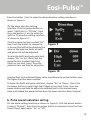
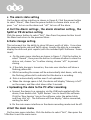
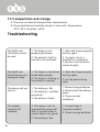
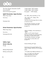
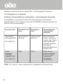
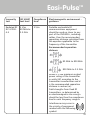
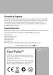
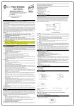
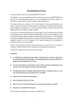
Warranty & Support
This product is provided with a one year warranty for problems found during
normal usage. Mistreating the Easi-Pulse or opening the unit will invalidate
this warranty. Any data stored on the unit and any consequential loss is not
covered by this warranty. The battery is not user replaceable.
Technical Support
Please visit www.tts-group.co.uk for the latest product information.
Email [email protected] for technical support.
TTS Group Ltd.
Park Lane Business Park
Kirkby-in-Ashfield
Nottinghamshire,
NG17 9GU, UK.
Freephone: 0800 318686 Freefax: 0800 137525
TTS Product Code:
Easi-Pulse
TM
WARNING: Do not dispose of this product in
household waste. Hand it over to a collection
point for recycling electronic appliances.
WARNING! Not suitable for children under 36
months due to small parts – choking hazard.
Made in China, on behalf of the TTS Group Ltd.
Nxxxxx
N448
EL00145
Easi-Pulse
TM
measures the pulse oxygen
saturation and pulse rate
USER GUIDE
www.tts-shopping.com
Instructions to User
Dear users, thank you very much for purchasing the Pulse Oximeter.
This Manual is written and compiled in accordance with the council directive
MDD93/42/EEC for medical devices and harmonized standards. In case of
modifications and software upgrades, the information contained in this
document is subject to change without notice.
The Manual describes, in accordance with the Pulse Oximeter’s features and
requirements, main structure, functions, specifications, correct methods
for transportation, installation, usage, operation, repair, maintenance and
storage, etc. as well as the safety procedures to protect both the user and
equipment. Refer to the respective chapters for details.
Please read the User Manual carefully before using this product. The User
Manual which describes the operating procedures should be followed
strictly. Failure to follow the User Manual may cause measuring abnormality,
equipment damage and human injury. The manufacturer is NOT responsible
for the safety, reliability and performance issues and any monitoring
abnormality, human injury and equipment damage due to users’ negligence
of the operation instructions. The manufacturer’s warranty service does not
cover such faults.
Owing to the forthcoming renovation, the specific products you received may
not be totally in accordance with the description of this User Manual. We
would sincerely regret for that.
This product is medical device, which can be used repeatedly.
2
Easi-Pulse
TM
WARNING:
n Uncomfortable or painful feeling may occur if using the device
continuously, especially for microcirculation barrier patients. It is
recommended that the sensor is applied for no longer than 2 hours.
n The device cannot be clipped on the edema or tender tissue.
n Do not attempt to look directly at the infra-red light emitter.
n Remove all cosmetics from the finger nail before use.
n Please refer to literature about the clinical restrictions and caution.
n This device is not intended for medical treatment.
The User Manual is published by Contec Medical Systems Co., LTD. All
rights reserved.
3
CONTENTS
4
1 Safety
5
1.1 Instructions for safe operation
5
1.2 Warnings
5
1.3 Attention
6
2 Overview
6
2.1 Features
6
2.2 Major applications and scope of application
7
2.3 Environment requirements
7
3 Principle
7
4 Technical specifications
8
4.1 Main performance
8
4.2 Main Parameters
8
5 Installation
9
5.1 View of the front panel
9
5.2 Battery installation
10
5.3 Accessories
10
6 Operating Guide
10
6.1 Application method
10
6.2 Operation
15
6.3 Clinical restrictions
15
7 Maintain transportation and storage
15
7.1 Cleaning
15
7.2 Maintainance
15
7.3 Transportation and storage
13
8 Troubleshooting
16
9 Key of Symbols
17
10 Function Specification
18
Appendix
19
Easi-Pulse
TM
1 Safety
1.1 Instructions for safe operations
Check the main unit and all accessories periodically to make sure that there
is no visible damage that may affect patient’s safety and check cables. It is
recommended that the device should be inspected once a week. When there
is obvious damage, stop using the device.
n Necessary maintenance must be performed by qualified service
engineers ONLY. There are no user serviceable parts and users are not
permitted to maintain it by themselves.
n The oximeter cannot be used together with devices not specified in
User’s Manual. Only the accessory that appointed or recommendatory
by manufacture can be used with this device.
n This product is calibrated before leaving factory.
1.2 Warning
n Explosive hazard—DO NOT use the oximeter in an environment with
inflammable gas such as some ignitable anesthetic agents.
n Ensure that the environment in which the device is operated is not
subject to any sources of strong electromagnetic interference, such as
radio transmitters, mobile telephones, etc.
n DO NOT use the oximeter during MRI and CT scans.
n Plastics contain rubber that some users may be allergic to.
n The disposal of the instrument and its accessories and packaging
(including battery, plastic bags, foams and paper boxes) should follow
the local laws and regulations.
n Please check the packing before use to make sure the device and
accessories are in accordance with the packing list.
n Please choose the accessories and probe which are approved or
manufactured by the manufacturer, other devices or accessories may
damage the device.
5
1.3 Attention
n Keep the oximeter away from dust, vibration, corrosive substances,
explosive materials, high temperature and moisture.
n If the oximeter gets wet, stop use.
n The Oximeter should be left to acclimatize to different environments.
n DO NOT the operate keys on front panel with sharp materials.
n High temperature or high pressure steam disinfection of the oximeter is
not recommended.
n Do not expose the Oximeter to liquids.
n When cleaning the device with water, the temperature should be lower
than 60°C.
n The update period of data is less than 5 seconds.
n Please read the measured value when the waveform on screen is equal
and steady. This measured value is optimal value.
n If some abnormal symbols appear on the screen during use, pull out
the finger and reinsert to restore normal use.
n This device has an alarm, users can check on this function according to
chapter 6.2 as a reference.
n A flexible circuit connects the halves of the device. Do not twist or pull
on the connection.
2 Overview
The pulse oxygen saturation is the percentage of HbO2 in the total Hb in
the blood, so-called the O2 concentration in the blood. It is an important
bio-parameter for respiration. A number of diseases relating to respiratory
system may cause a decrease of SpO2 in the blood.
2.1 Features
A. Operation of the product is simple and convenient.
B. The product is compact, light in weight and convenient to carry.
C. Low power consumption
2.2 Major applications and scope of application
The Pulse Oximeter can be used in measuring the pulse oxygen saturation
6
Easi-Pulse
TM
and pulse rate through finger. The product is suitable for being used at
home, in the hospital, at an oxygen bar, in community healthcare, and
for physical care in sports (it can be used before or after sports, it is not
recommended to use the device during sport) and etc.
2.3 Environment requirements
Storage Environment
a) Temperature :-40°C +60°C
b) Relative humidity :5% 95%
c) Atmospheric pressure :500hPa 1060hPa
Operating Environment
a) Temperature:10°C 40°C
b) Relative Humidity :30% 75%
c) Atmospheric pressure:700hPa 1060hPa
3 Principle
Principle of the Oximeter is as follows: using Lambert Beer Law and
according to Spectrum Absorption Characteristics of Reductive Hemoglobin
(Hb) and Oxyhemoglobin (HbO2) in glow & near-infrared zones. Operation
principle of the device is: Photoelectric Oxyhemoglobin Inspection
Technology is adopted in accordance with Capacity Pulse Scanning &
Recording Technology, so that two beams of different wavelength of lights
can be focused onto human nail tip through perspective clamp finger-type
sensor. Then the measured signal can be obtained by a photosensitive
element, information acquired through which will be shown on screen.
Glow and Infraredray Emission tube
Glow and Infraredray Receit tube
7
4 Technical specifications
4.1 Main performance
A. SpO2 value display
B. Pulse rate value display, bar graph display
C. Pulse waveform display
D. Low-voltage indication
E. Automatically power off: it will automatically power off within 5
seconds if the finger falls out of probe.
F. The display mode can be changed
G. A pulse rate sound indication
H. Alarm function
I. With SpO2 value and pulse rate data storage, the stored data can be
uploaded to computers
J. Data can be transmitted to computers
4.2 Main Parameters
A. Measurement of SpO2
Measuring range: 0% 100
Accuracy:
When the SpO2 measuring range is 70% 100,the permission of absolute
error is ±2
below 70% unspecified
B. Measurement of pulse rate
Measuring range:30bpm 250bpm
Accuracy: ±2 bpm or ±2% (select larger)
C. Resolution
SpO2 : 1%, Pulse rate: 1bpm.
8
Easi-Pulse
TM
D. Measurement Performance in Weak Filling Condition
SpO2 and pulse rate can be shown correctly when pulse-filling ratio is 0.4%.
SpO2 error is ±4%, pulse rate error is ±2 bpm or ±2% (select larger).
E. Resistance to surrounding light
The deviation between the value measured in the condition of man-made
light or indoor natural light and that of darkroom is less than ±1%.
F. Power supply requirement: 2.6 V DC ~ 3.6V DC.
G. Optical Sensor
Red light (wavelength is 660nm 6.65mW)
Infrared (wavelength is 880nm, 6.75mW)
H. Adjustable alarm range:
SpO2 0%~100%
Pulse Rate: 0bpm~250bpm
5 Installation
5.1 View of the front panel
9
5.2 Battery installation
A. Refer to Figure 3. and insert the two AAA size batteries with the
correct polarity.
B. Replace the cover.
Figure 3
5.3 Accessories
A. Lanyard
C. User manual
B. Two dry batteries (AAA)
(optional)
D. USB lead
E. CD (PC software)
6 Operating Guide
6.1 Application method
A.
a) Insert the two batteries
ensuring the correct
polarity, and then replace
the cover.
b) Open the clip as shown
in Figure 4.
c) Insert the finger into the
foam rubber cushions
of the clip (make sure
the finger is in the right
position), and then
release the clip onto the
finger.
10
d) The data can be read
directly from the screen
on the measuring
interface.
Figure 4 Put finger in position
Easi-Pulse
TM
B. Change display direction
On the measuring interface, press the button to change the display.
C. Pause alarm:
a) Alarm including can be set to sound for data going beyond the
predetermined limits, low battery, and finger removed.
c) To turn off the alarm, setting can be changed in the operation menu.
D. Data transmission setting
Firstly, please install the affiliated software onto the computer, two icons
will appear on the desktop after installation. SpO2 is a program for receiving
real-time data which is shown as Figure 5; the icon of SpO2 Review is a
program for receiving stored data which is shown as Figure 6.
a. Please connect the device to the computer with the USB lead , then
double click the “SpO2 “icon to start the program.
b. When you unplug the USB lead from the computer, a dialog box will
appear “Save data at view” on the desktop, at this point you will be
prompted to input basic user information if required.
E. Menu operations
Figure 5 SpO2 program
Figure 5 SpO2 Review program
11
On the measuring interface, the display direction can be changed by
pressing the power button quickly. There are six modes of data display that
can be viewed.
a. Adjusting the high and low limits of alarms
On the alarm setting interface, Click the power button to select “Dir”, then
Press and hold the power button (1
second) to enter the Settings Menu
Interface (see Figure 7).
The user can setup the following
parameters in the Settings Menu –
Turn on alarm; turn on pulse sound,
alarm high-low limits, data storage
(recording).
Please note in the Settings Menu:
Figure 7
CLICK = short press of power button
and PRESS = prolonged push of
power button (1sec)
a) Alarm setting
On the main menu interface, click
the power button to select “Alarm”,
Press the power button (1sec) to
enter the alarm setting interface as
shown in Figure 8:
Figure 8
12
Easi-Pulse
TM
Press the button (1sec) to enter the alarm direction setting interface as
shown in Figure 9:
On the alarm direction setting
interface, Click the power button to
select “SpO2 Alm”or “PR Alm”, then
Press the button (1 sec) to enter the
SpO2 or PR direction setting interface
as shown in Figure 10:
Click the power button to select “Dir”,
then Press the button to choose Up
or Down (this will be the direction the
value of the high-low limits of SpO2
and pulse rate will be adjusted)
Figure 9
To raise the SpO2 and pulse rate limit,
choose “Dir” as ‘Up’, then Click the
power button to select high limit
(High) or low limit (Low), Press the
power button and hold to adjust the
Figure 10
selected limit to the desired higher value and release the power button once
the higher limit has been reached.
To lower the SpO2 and pulse rate limit, choose “Dir” as ‘Down’, then Click
the power button to select high limit (High) or low limit (Low). Press the
power button and hold to adjust the selected limit to the desired lower
value and release the power button once the lower limit has been reached.
b. Pulse sound indication setting
On the alarm setting interface as shown in Figure 8, Click the power button
to select “Psound”, then Press the power button to choose to have the Pulse
Sound (heart beat) alarm “on” or “off”.
13
c. The alarm state setting
On the alarm setting interface as shown in Figure 8, Click the power button
to select “Alarm”, then Press the power button to choose alarm on or off,
press “ on” to turn on the alarm and “ off” to turn off the alarm.
d. Exit the Alarm settings , the alarm direction setting , the
SpO2 or PR direction setting
Click the power button to select “Exit”, then Press the power button to exit
the Menu and return to the previous Menu .
b Data storage setting
This instrument has the ability to store 24 hours worth of data. It can store
the measured pulse rate and SpO2 values, transfer the data to a computer,
display the data and print reports (with the included SpO2 Software - Green
Heart)
a. On the main menu interface as shown in Figure 7, Click the button to
select “Record”, then press the button to choose whether to store the
data or not, choose “on” to allow storing, choose “off ” to prevent
storing.
b. If the data storage is turned on, the main user interface will show a
flashing yellow dot.
c. Whilst recording the screen will be automatically shut down, with only
the flashing yellow dot to indicate that the device is recording.
d. Data is automatically written over if not uploaded.
e. When the storage space is full, the device will display “Memory is full”
on the screen, and then shut down after 3 seconds.
c Uploading the data to the PC after recording
a. Connect the device to a computer via the USB lead supplied with the
device, then double click “SpO2 Review” icon to launch the software.
Click the ‘New Session’ Icon in the software, enter the patient data
and then click ‘ok’. The Software will then display “device connected,
waiting for data”.
b. On the main menu interface on the device recording mode must be off.
d Exit the main menu
On the main menu interface, Click the button to select “Exit”, then press the
14 button to exit the main menu.
Easi-Pulse
TM
F. Power off
The device will power off automatically when it gets no signal for 5 seconds.
The device cannot power off when it is storing data.
6.2 Attention for operation
A. Please check the device before use.
B. The finger should be in a proper position (see the attached illustration
of Figure 4 for reference), or else it may result in an inaccurate
measurement.
C. The SpO2 sensor should not be used at a location or with a limb with
an arterial canal or blood pressure cuff or whilst receiving intravenous
injection.
D. Do not fix the SpO2 sensor with adhesive.
E. Excessive ambient light may affect the measuring result.
F. Strenuous action of the subject or extreme electrosurgical interference
may also affect the accuracy.
G. Please clean and disinfect the device after operating according to the
User Manual(7.1).
6.3 Clinical restrictions
A. Some medical conditions will affect the SpO2 reading by this monitor and
may be inaccurate.
7 Maintenance, transportation and storage
7.1 Cleaning and Disinfecting
Use medical alcohol to disinfect the device, nature dry or clean it with clean
soft cloth.
7.2 Maintenance
A. Please clean and disinfect the device before using according to the User
Manual(7.1).
B. Please change the battery when the screen shows.
C. Remove the battery from the device for long periods of storage.
15
7.3 Transportation and storage
A. There are not special transportation requirements.
B. The packed device should be stored in room with: Temperature:
-40°C~60°C; Humidity: ≤95%
Troubleshooting
The SpO2 and
Pulse Rate cannot
be read
1. The finger is not
properly positioned
1. Place the finger properly
and try again.
2. The patient’s SpO2 is
too low to be detected.
2. Try again; Go to a
hospital for a diagnosis
if you are sure the device
works all right.
The SpO2 and
Pulse Rate are not
displayed stably
1. The finger is not placed
inside deep enough.
1. Place the finger properly
and try again.
2. The finger is shaking or
the patient is moving.
2. Let the patient keep
calm.
The device will not
turn on
1. The battery is flat.
1.Please change batteries.
2.Please Install the battery
again.
2. The battery is installed
incorrectly.
3. The device is faulty.
The display
switches off
suddenly
1. This device is set to
automatically power off
after 5 seconds when it
cannot detect any signal.
2. The battery is flat.
16
3. Please contact
distributer.
1. Ensure finger is
correctly inserted
2. Please change batteries.
Easi-Pulse
TM
9 Key of Symbols
Warning – See User Manual
%SpO2
The pulse oxygen saturation(%)
PRbpm
Pulse rate (bpm)
Low-voltage
Open the alarm sound indication
Open the pulse sound indication
menu button/power button/function button
Type BF
SN
---
Serial number
1. the finger clip falls off ( no finger inserted)]
2. Probe error
3. Signal inadequacy indicator
battery positive
battery negative
USB
IPXI
Ingress of liquids rank
WEEE (2002/96/EC)
This item is compliant with Medical Device Directive
93/42/EEC of June 14, 1993, a directive of the
European Economic Community.
17
The Pulse Oxygen Saturation (SpO2)
2-digit digital OLED display
Pulse Rate(PR)
3-digit digital OLED display
Pulse Intensity (bar-graph)
bar-graph
SpO2 Parameter Specification
OLED display
Measuring range
0%-100%, (the resolution is 1%).
Accuracy
70%-100% ±2% , Below 70%
unspecified.
Average value
Calculate the Average value in every
4 measure value.
The deviation between average
value and true value does not
exceed 1%.
Pulse Parameter Specification
Measuring range
Accuracy
Average pulse rate
30bpm-250bpm, (the resolution is
1bpm)
±2bpm or±2% (select larger)
Moving calculate the Average pulse
rate every 4 cardio-beats cycle.
The deviation between average
value and true value does not
exceed 1%
Safety Type
Pulse Intensity
Interior Battery, BF Type
Range
Battery Requirement
Continuous bar-graph display, the
higher display indicates the stronger
pulse.
Battery working life
1.5V (AAA size) alkaline batteries × 2
18
Two 1.5V (AAA size) 600mAh
alkaline batteries can work
continually for 24 hours
Easi-Pulse
TM
Dimensions and Weight
Dimensions
58.5(L) × 31(W) × 32 (H) mm
Weight
About 52g (with the batteries)
Appendix
Guidance and manufacturer’s declaration – electromagnetic emissionsfor all Equipment and Systems
Guidance and manufacturer’s declaration – electromagnetic emission
The CMS50D+ is intended for use in the electromagnetic environment
specified below. The customer of the user of the CMS50D+ should assure that
it is used in such and environment.
Emission test
Compliance
Electromagnetic environment –
guidance
RF emissions
CISPR 11
Group 1
The CMS50D+ uses RF energy only
for its internal function. Therefore,
its RF emissions are very low and are
not likely to cause any interference in
nearby electronic equipment.
RF emission
CISPR 11
Class B
The CMS50D+ is suitable for use in all
establishments other than domestic
and those directly connected to a low
voltage power supply network which
supplies buildings used for domestic
purposes.
19
Guidance and manufacturer’s declaration – electromagnetic immunity –
for all Equipment and Systems
Guidance and manufacturer’s declaration – electromagnetic immunity
The CMS50D+ is intended for use in the electromagnetic environment
specified below. The customer or the user of CMS50D+ should assure that it is
used in such an environment.
Immunity test
IEC 60601 test
level
Compliance
level
Electromagnetic
environment guidance
Electrostatic
discharge (ESD)
±6 kV contact
±8 kV air
±6 kV contact
±8 kV air
Floors should be
wood, concrete or
ceramic tile. If floor
are covered with
synthetic material,
the relative
humidity should be
at least 30%.
3A/m
3A/m
Mains power
quality should be
that of a typical
commercial
or hospital
environment.
IEC 61000-4-2
Power
frequency
(50/60Hz)
magnetic field
IEC 61000-4-8
NOTE UT is the a.c. mains voltage prior to application of the test level.
20
Easi-Pulse
TM
Immunity
test
IEC 60601
test level
Compliance
level
Electromagnetic environment guidance
Radiated RF
IEC 610004-3
3 V/m
80 MHz to
2.5 GHz
3 V/m
Portable and mobile RF
communications equipment
should be used no closer to any
part of the CMS50D+, including
cables, than the recommended
separation distance calculated from
the equation applicable to the
frequency of the transmitter.
Recommended separation
distance
80 MHz to 800 MHz
800 MHz to 2.5 GHz
Where P is the maximum output
power rating of the transmitter
in watts (W) according to the
transmitter manufacturer and d
is the recommended separation
distance in metres (m).
Field strengths from fixed RF
transmitters, as determined by
an electromagnetic site survey,a
should be less than the compliance
level in each frequency range b.
Interference may occur in
the vicinity of equipment
marked with the following
symbol:
21
NOTE 1 At 80 MHz and 800 MHz, the higher frequency range applies.
NOTE 2 These guidelines may not apply in all situations. Electromagnetic
propagation is affected by absorption and reflection from structures, objects
and people.
a Field strengths from fixed transmitters, such as base stations for radio
(cellular/cordless) telephones and land mobile radios, amateur radio,
AM and FM radio broadcast and TV broadcast cannot be predicted
theoretically with accuracy. To assess the electromagnetic environment
due to fixed RF transmitters, an electromagnetic site survey should
be considered. If the measured field strength in the location in which
the CMS50D+ is used exceeds the applicable RF compliance level
above, the CMS50D+ should be observed to verify normal operation.
If abnormal performance is observed, additional measures may be
necessary, such as reorienting or relocating the CMS50D+.
b Over the frequency range 150 kHz to 80 MHz, field strengths should be
less than 3 V/m.
22
Easi-Pulse
TM
Recommended separation distances between portable and mobile RF
communications equipment and the CMS50D+
The CMS50D+ is intended for use in an electromagnetic environment in
which radiated RF disturbances are controlled. The customer or the user of
the CMS50D+ can help prevent electromagnetic interference by maintaining
a minimum distance between portable and mobile RF communications
equipment (transmitters) and the CMS50D+as recommended below, according
to the maximum output power of the communications equipment.
Rated maximum
output power of
transmitter
(W)
Separation distance according to
frequency of transmitter (m)
80 MHz to 800 MHz
800 MHz to 2.5 GHz
0.01
0.12
0.23
0.1
0.37
0.74
1
1.17
2.33
10
3.69
7.38
100
11.67
23.33
For transmitters rated at a maximum output power not listed above, the
recommended separation distance d in metres (m) can be estimated using
the equation applicable to the frequency of the transmitter, where P is the
maximum output power rating of the transmitter in watts (W) according to the
transmitter manufacturer.
NOTE 1 At 80 MHz and 800 MHz, the separation distance for the higher
frequency range applies.
NOTE 2 These guidelines may not apply in all situations. Electromagnetic
propagation is affected by absorption and reflection from structures, objects
and people.
23