1
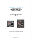
Flybox
®
Electronic Flap Controller
EFC-P
Revision# 3.1 17/7/2015
For firmware version 1.5
Page intentionally left blank
SECTIONS
MECHANICAL INSTALLATION
TRANSDUCER & ACTUATOR INSTALLATION
ELECTRICAL INSTALLATION
USE OF THE INSTRUMENT
TECHNICAL SPECIFICATIONS
FLYBOX®
Introduction
Thank you for purchasing a Flybox® product. We hope
it fully satisfy you and makes your flights pleasant and
secure.
Developing EFC-P, our intent was to create a compact
and lightweight flap controller, easy to install and use.
SYMBOLS USED IN THE MANUAL
NOTE: Used to highlight important informations.
CAUTION: Used to warn the user and indicate a potentially
hazardous situation or improper use of the product.
WARNING: Used to indicate a dangerous situation that can
cause personal injury or death if the instruction is
disregarded.
EFC-P - User’s manual
Rev. 3.1
FLYBOX
®
Important notices & warnings
NOTE: Although the EFC-P has been heavily tested to
ensure the maximum safety in every condition, the correct
operation depends also by installation and wiring, that must
be accurately made and verified reading completely this
manual.
NOTE: Keep this manual in the aircraft.
This document must accompany the instrument in the event
of change of ownership.
NOTE: This device is intended for installation onto non type
certified aircraft only, because it has no aviation certifications.
Refer to your local aviation authorities to check if this device
may be installed in your aircraft.
CAUTION: Read entirely this manual before installing the
instrument in your aircraft, and follow the installation and
operating instructions described here.
CAUTION: The pilot must understand the operation of this
instrument prior to flight, and must not allow anyone to use
it without knowing the operation. Don't use this instrument
in flight until you are sure of the correct operating of the same.
CAUTION: When the installation is finished you must do a
test, prior to flight, switching on all the possible source of
electric noise and checking the properly operation of this
instrument.
CAUTION: Using this instrument over the maximum
allowable ranges can cause malfunction or wrong indications.
EFC-P - User’s manual
Rev. 3.1
Important notices & warnings
FLYBOX®
WARNING: the EFC-P must be turned off in case of start
with booster. open the corresponding breaker before starting.
warranty shall not apply for damage to the EFC-P for this
reason.
WARNING: The EFC-P is attached directly to the flaps
actuator: the non-respect of the notices above or a damage
to the EFC-P may result in unexpected movements of the
flaps. In this situation you must immediately disable the
EFC-P by turning the switch in the “MANUAL” position (see
chap.4.4 “Use in MANUAL mode”).
WARNING: Responsibility for installation lies entirely with the
installer. Responsibility for operations lies entirely with the
operator.
IMPORTANT: If you do not agree with the notices above
do not install this instrument in your aircraft, but return
the product for a refund.
Microel s.r.l. reserves the right to change or improve its
products. Information in this document is subject to changes
without notice.
EFC-P - User’s manual
Rev. 3.1
FLYBOX
®
Index
SECTION 1
1.1 Mechanical installation
Rectangular panel version
2”¼ round panel version
9
9
10
SECTION 2
2.1 Transducer installation
2.2 Actuator installation
13
SECTION 3
3.1 Electrical installation
15
3.2
3.3
3.4
3.5
Wiring diagram for actuator with no
internal limit switches
Wiring diagram for actuator with
internal limit switches
Wiring diagram for actuator with
internal limit switches and external
wires
Wirings check
EFC-P - User’s manual
Rev. 3.1
11
17
17
18
19
FLYBOX®
Index
SECTION 4
4.1 Panel indicators and commands
4.2 Operation instructions
4.3 Use in AUTOMATIC mode
4.4 Use in MANUAL mode
4.5 Troubleshooting and
error code
25
SECTION 5
5.1 Technical specifications
26
Warranty
20
21
23
24
27
EFC-P - User’s manual
Rev. 3.1
FLYBOX
®
Mechanical installation
SECTION 1
1.1 MECHANICAL INSTALLATION
Ractangular panel version (EFC-P)
Dimensions in millimeters
Panel cut-out
EFC-P - User’s manual
Rev. 3.1
9
FLYBOX®
Mechanical installation
2”1/4 round panel version (EFC57-P)
Dimensions in millimeters
10
EFC-P - User’s manual
Rev. 3.1
FLYBOX
®
Transducer installation
SECTION 2
2.1 TRANSDUCER INSTALLATION
(only if using actuator without
integrated transducer)
The installation consists in the mechanical coupling
between the flaps actuator (motor) and the transducer
(potentiometer) which permits the EFC-P to know the
actual flaps position.
Example of mechanical installations actuator-transducer
EFC-P - User’s manual
Rev. 3.1
11
FLYBOX®
Transducer installation
NOTE:
- The transducer's travel must be at least 10mm more
then the actuator's travel.
- The electrical resistance of the transducer must be
from 1 to 10 Kohm.
- The transducer must be centered over the actuator's
travel so that it isn't possible to exit from the limits, with
consequently damage to the position's transducer.
12
EFC-P - User’s manual
Rev. 3.1
FLYBOX
®
Actuator installation
2.2 ACTUATOR INSTALLATION
If the actuator doesn't have any internal limit switches
it's necessary to install them externally.
To avoid the possibility of mechanical and electrical
damage, the actuator travel must match exactly with
the flaps travel: with the actuator completely retracted
(limit switch reached) the flaps must be completely
retracted (or completely extracted for inverse
mechanical coupling); with the actuator completely
extracted the flaps must be completely extracted (or
completely retracted for inverse mechanical coupling).
Adjust your actuator travel if it does not coincide with
the flaps travel, for example using an arm/lever with an
appropriate length.
If the condition above indicated is not satisfied the
actuator is not protected against possible overtravel
during flap extension and retraction, therefore a pilot
that drive the flaps manually (for example
using
“Manual” mode of the EFC-P) can cause mechanical
damage if he don't stop exactly when the flaps have
reached the up and down positions.
EFC-P - User’s manual
Rev. 3.1
13
FLYBOX®
Actuator installation
Correct installation: actuator travel exactly match flaps
travel.
IMPORTANT NOTES ON USING ACTUATORS WITH
INTEGRATED TRANSDUCER:
- The electrical resistance of the transducer must be from 1
to 10 Kohm.
- Choose a model that use the maximum electrical
resistance range. For example if you choose an actuator
with 10 Kohm transducer, verify that the stroke that you are
going to use provide at least a variation of half the
transducer's resistance, i.e. 5 Kohm.
14
EFC-P - User’s manual
Rev. 3.1
FLYBOX
®
Electrical installation
SECTION 3
3.1 ELECTRICAL INSTALLATION
In the backpanel there is a 10-poles plug connector (model:
MOLEX Mini-Fit JR.); the corresponding socket connector is
delivered with your EFC-P.
Backpanel plug
Socket view (from wire'insertion side)
EFC-P - User’s manual
Rev. 3.1
15
FLYBOX®
Electrical installation
Connector pinout:
1 – Motor out (-)
2 – Power input (+12V)
3 - Positive voltage (+5V) for the position's transducer
4 – Position's transducer signal
5 – Ground for the position's transducer
6 – Motor out (+)
7 – Power input (GND)
8 – “DOWN” limit switch
9 – Limit switches common connection
10 – “UP” limit switch
NOTE: Insert a breaker to the power lead (+12V);
choose a correct amperage depending on the actuator
installed.
Use avionic cable.
It’s recommendend to use shielded cable
poles+shield) for the motor output (pin#1 &
connecting the shield of the cable to ground on
EFC-P side and leaves disconnected the shield on
actuator side.
(2
6),
the
the
WARNING: Voltage peaks higher than 15 Volt on the
supply line can damage the device.
WARNING: The EFC-P must be turned off in case of
start with booster. Open the corresponding breaker
before starting.
16
EFC-P - User’s manual
Rev. 3.1
FLYBOX
®
Electrical installation
3.2 WIRING DIAGRAM FOR ACTUATOR WITH
NO INTERNAL LIMIT SWITCHES
If the actuator used has no internal limit switches you must
install them externally and follow the wiring diagram below.
The UP and DOWN switches must be normally closed; diodes
max current must be at least 3 Ampere.
Pay attention to the UP and DOWN limit switches mechanical
and electrical installation, because a wrong connection can
prevent the EFC-P from turn off the actuator before the
mechanical stop, with possible damage to the actuator itself.
Wiring diagram for actuator with no internal limit switches
3.3 WIRING DIAGRAM FOR ACTUATOR WITH
INTERNAL LIMIT SWITCHES
If the actuator used has integrated limit switches and wiring
(no external wires) use the wiring diagram above, connecting
pin #1 and #6 of the EFC-P connector directly to the actuator.
EFC-P - User’s manual
Rev. 3.1
17
FLYBOX®
Electrical installation
3.4 WIRING DIAGRAM FOR ACTUATOR WITH
INTERNAL LIMIT SWITCHES AND
EXTERNAL WIRES
If the actuator used has 3 wires for the limit switches
connection, probably one wire is the common contact for the
limit switches, so the wiring diagram to the EFC-P is the
following:
Wiring diagram for actuator with internal limit switches and external wires.
Note that the common contact of the limit switches is connected to pin
#9.
18
EFC-P - User’s manual
Rev. 3.1
FLYBOX
®
Electrical installation
3.5 WIRINGS CHECK
FIRST CHECK:
When finished all the wirings turn the Auto/Manual switch in
Manual position and check the flaps movement with the
UP/DOWN switch: press in “DOWN” position and check that
the flaps go down, press in “UP” position and check that the
flaps go up. If directions are reversed swap the two actuators
wire (pin 1 and 6 on the EFC-P connector).
SECOND CHECK:
The wiring between the transducer and the EFC-P connector
(pins 3-5) depends on the actuator-transducer mechanical
coupling (i.e. flaps down-->transducer's shaft extracted or
flaps down-->transducer's shaft retracted).
To check if the wirings are ok measure the voltage between
ground (pin#7) and pin #4 of the EFC-P connector:
with the flaps completely down the voltage must be to its
maximum value, with the flaps completely up the voltage
must be to its minimum. If this doesn't occur, or if the EFC-P
does not work correctly, swap the two wires on pins #3 and
#5 of the EFC-P connector.
EFC-P - User’s manual
Rev. 3.1
19
Panel indicators & commands
FLYBOX®
SECTION 4
4.1 PANEL INDICATORS AND COMMANDS
LED 1
LED 2
A/M switch
(Auto/Manual)
U/D switch
(Up/Down)
LED 3
LED 4
NOTE: The Auto/Manual switch has a safety lock to
avoid accidental operation: it must first pulled on the
outside and then moved to the desired position.
20
EFC-P - User’s manual
Rev. 3.1
FLYBOX
®
Operation instructions
4.2 OPERATION INSTRUCTIONS
The EFC-P can work in two modes: Automatic or Manual.
For normal operations use the “Automatic” mode; the
“Manual” mode must be used only in case of emergency or
failure of the EFC-P.
NOTE: Before using the device for the first time you must
program the four position that the EFC-P store in memory
and use in Automatic mode. Follow this steps to perform the
programming:
● With the device powered off turn the A/M switch in the
“Automatic” position, then press and hold the U/D switch
in the “UP” position..
● Power on the EFC-P and wait 10 seconds until the LED1
and the LED4 come on steady.
● Release the U/D switch (LED1 and LED4 start flashing).
NOTE: The EFC-P doesn't enter in the programming
mode if a limit switch is open (UP or DOWN limit switch);
if this occour you must turn in “Manual” mode and move
the flaps until the limit switch will de-activate, then repeat
the programming sequence from the beginning.
EFC-P - User’s manual
Rev. 3.1
21
FLYBOX®
Operation instructions
● Make this sequence using the U/D switch: 2 click in the
UP position, 2 click in the DOWN position and 1 click in
UP; if the sequence is correct the EFC-P enters in
programming mode and the LED2/LED3 briefly flash.
● Now the first led is flashing indicating that you can adjust
the flaps in the desired position (using the U/D switch).
To store the position, briefly move the A/M switch in
“Manual” and then return in “Automatic”.
● Now the second led is flashing and you can adjust and
then store the second position in the same way explained
in the previous step (U/D switch to adjust then A/M
switch to store the position). Repeat again the step for
the third and fourth position.The EFC-P will automatically
exit from the programming mode and become operative
once the last position is correctly stored in memory.
NOTE: If the EFC-P is powered on the first time without enter
in the programming mode the four LED will simultaneously
flash.
The positions remains stored in memory also without
power supply.
22
EFC-P - User’s manual
Rev. 3.1
FLYBOX
®
Use in AUTOMATIC mode
4.3 USE IN AUTOMATIC MODE
In AUTOMATIC mode you can move the flaps choosing one
of the four stored position; the maximum travel of the motor
is defined by the two limit switches UP and DOWN.
The LEDs show the status of the flaps:
LED on: indicate the current position of the flaps
LED flashing: indicate the position that the flaps are reaching
-EXAMPLE OF USEThe flaps are in the first position (LED1 on, all other LEDs
off):
to move the flaps in the third position press two times the U/D
switch in the DOWN position; the flaps start moving and the
third LED is flashing, indicating the position that the flaps are
reaching.
When the flaps reaches the second position the first LED turn
off while the second turn on; when they reaches the third
position the second LED turn off and the third turn on. The
flaps have reached the selected position and the EFC-P
return to steady state, waiting for another command.
Pressing the U/D switch in the UP position for more than 1
second move automatically the flaps to the first position
(regardless of the current position).
EFC-P - User’s manual
Rev. 3.1
23
FLYBOX®
Use in MANUAL mode
4.4 USE IN MANUAL MODE
In this mode the flaps position are not fixed between the four
programmed positions but the movement are continuous;
however it's recommended to use the MANUAL mode only
in case of device's electronic failure, because this mode
bypass the internal electronic circuits and connect directly
the motor to the U/D switch.
To control the flaps simply use the U/D switch: press and hold
in a position (UP or DOWN) and release when the motor have
reached the desired position.
24
EFC-P - User’s manual
Rev. 3.1
FLYBOX
®
Troubleshooting and error code
4.5 TROUBLESHOOTING AND ERROR CODE
● All the four LEDs flashing: no positions' programming
have been made (see chap. 4.2)
● LED1 and LED2 flashing: it means that the EFC-P try
to move the motor but there is no feedback from the
transducer: can be a wrong connections on the motor's
wiring or on the transducer's wiring.
To exit from this condition you must turn off the device
and remove the cause of failure.
● LED1 and LED3 flashing: it means that the connection
motor/transducer are not correct; maybe the motor's
wire reversal or a wrong tranducer wiring.
To exit from this condition you must turn off the device
and remove the cause of failure.
● LED2 and LED4 flashing: it means that the EFC-P has
detected an over-current condition. Check that wirings
of the actuator motor have no short circuits or check
that the actuator is working correctly.
EFC-P - User’s manual
Rev. 3.1
25
Technical specifications
FLYBOX®
SECTION 5
5.1 TECHNICAL SPECIFICATIONS
● Frontpanel dimensions:
61.8 x 71.8 mm (rectangular panel version).
60.0 x 60.0 mm (2”1/4 round panel version).
● Depth:
46 mm (rectangular panel version).
52 mm (2”1/4 round panel version).
● Weight: 125 g.
● Power requirements: 12 ~ 20 V=, 80 mA.
● Maximum current supplied to the motor: 7 Ampere.
● Operating temperature range: -20 ~ +70 °C.
● Relative humidity: 10% ~ 90% without condensation.
26
EFC-P - User’s manual
Rev. 3.1
FLYBOX
®
WARRANTY:
This product is warranted to be free from defects for a
period of 12 months from the user invoice date.
The warranty only cover the manufacture's defects; shall
not apply to product that has been improper installed,
misused or incorrect maintenance, repaired or altered
by non-qualified person.
Date
06/2011
11/2014
7/2015
Revision
2.8
3.0
3.1
Description
First release
Layout update
Updated chap.4.2
WARNING: All photos, data, drawings, instruments layouts, technical solutions and
data representation you find in this document or watching at FLYBOX® instruments
working and/or you can access by means of any other media, including web sites,
are sole property of MICROEL s.r.l., cannot be copied or imitate without a written
permission of MICROEL s.r.l. itself and are protected by law, even by means of
extended international copyright and/or specific patents deposited. Any infringement
of this statement and of MICROEL s.r.l. intellectual property will be prosecuted.
©2015 Microel s.r.l. – all rights reserved.
EFC-P - User’s manual
Rev. 3.1
27
MICROEL s.r.l.
Via Mortara 192-194
27038 Robbio (PV) - ITALY
Tel +39-0384-670602 - Fax +39-0384-671830
www.flyboxavionics.it