1
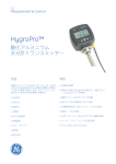
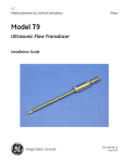
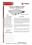
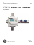
GE
Sensing & Inspection Technologies
HygroPro
Moisture Transmitter
User’s Manual
916-099C
October 2008
GESensingInspection.com
©2008 General Electric Company. All rights reserved.
Technical content subject to change without notice.
GE
Sensing & Inspection Technologies
HygroPro
Moisture Transmitter
User’s Manual
©2008 General Electric Company. All rights reserved.
Technical content subject to change without notice.
916-099C
October 2008
Page 1
Contents
Chapter 1: Installation
1.1 Introduction . . . . . . . . . . . . . . . . . . . . . . . . . . . . . . . . . . . . . . . . . .5
1.2 Sample System Guidelines . . . . . . . . . . . . . . . . . . . . . . . . . . . . . .6
1.3 Mounting the Transmitter . . . . . . . . . . . . . . . . . . . . . . . . . . . . . . .8
1.4 Wiring the Transmitter . . . . . . . . . . . . . . . . . . . . . . . . . . . . . . . . .9
1.4.1 Standard Wiring Connections . . . . . . . . . . . . . . . . . . . . . .10
1.4.2 Hazardous Area Wiring Connections . . . . . . . . . . . . . . . .15
Chapter 2: Operation
2.1 Powering Up & Programming. . . . . . . . . . . . . . . . . . . . . . . . . . .23
2.1.1 Menu Map . . . . . . . . . . . . . . . . . . . . . . . . . . . . . . . . . . . . .24
2.1.2 Keypad. . . . . . . . . . . . . . . . . . . . . . . . . . . . . . . . . . . . . . . .25
2.2 Basic Setup . . . . . . . . . . . . . . . . . . . . . . . . . . . . . . . . . . . . . . . . .25
2.2.1 Unlocking the Display . . . . . . . . . . . . . . . . . . . . . . . . . . . .25
2.2.2 Entering the Setup Program. . . . . . . . . . . . . . . . . . . . . . . .26
2.2.3 Selecting Measurement Parameters. . . . . . . . . . . . . . . . . .27
2.2.4 Setting Up the Display. . . . . . . . . . . . . . . . . . . . . . . . . . . .29
2.2.5 Setting Up the Analog Output . . . . . . . . . . . . . . . . . . . . . .30
2.2.6 Entering the Node ID. . . . . . . . . . . . . . . . . . . . . . . . . . . . .32
2.2.7 Setting Up the RS485 Output . . . . . . . . . . . . . . . . . . . . . .33
2.3 Advanced Setup. . . . . . . . . . . . . . . . . . . . . . . . . . . . . . . . . . . . . .34
2.3.1 Setting Up the Pressure/Temperature Displays . . . . . . . . .34
2.3.2 Entering Sensor Calibration Data . . . . . . . . . . . . . . . . . . .35
2.3.3 Locking and Unlocking the Keypad . . . . . . . . . . . . . . . . .37
2.3.4 Locking and Unlocking the Menus . . . . . . . . . . . . . . . . . .37
HygroPro User’s Manual
Page 3
Contents
Chapter 3: Service & Maintenance
3.1 The Service Menus . . . . . . . . . . . . . . . . . . . . . . . . . . . . . . . . . . 39
3.2 Moisture Probe Error Conditions. . . . . . . . . . . . . . . . . . . . . . . . 40
3.3 Cleaning the Moisture Probe . . . . . . . . . . . . . . . . . . . . . . . . . . . 40
3.3.1 Preparing to Clean the Probe . . . . . . . . . . . . . . . . . . . . . . 40
3.3.2 Replacing the RTE . . . . . . . . . . . . . . . . . . . . . . . . . . . . . . 41
3.3.3 Removing the Transmitter from the System . . . . . . . . . . 42
3.3.4 Removing the Probe from the Transmitter. . . . . . . . . . . . 42
3.3.5 Cleaning the Sensor and the Shield . . . . . . . . . . . . . . . . . 44
3.3.6 Installing the Probe in the Transmitter . . . . . . . . . . . . . . . 45
3.3.7 Evaluating the Cleaned Probe . . . . . . . . . . . . . . . . . . . . . 45
Chapter 4: Specifications
4.1 General. . . . . . . . . . . . . . . . . . . . . . . . . . . . . . . . . . . . . . . . . . . . 47
4.2 Electrical . . . . . . . . . . . . . . . . . . . . . . . . . . . . . . . . . . . . . . . . . . 48
4.3 Mechanical. . . . . . . . . . . . . . . . . . . . . . . . . . . . . . . . . . . . . . . . . 49
4.4 Moisture Sensor . . . . . . . . . . . . . . . . . . . . . . . . . . . . . . . . . . . . . 50
4.5 Built-In Temperature Sensor . . . . . . . . . . . . . . . . . . . . . . . . . . . 50
4.6 Built-In Pressure Sensor . . . . . . . . . . . . . . . . . . . . . . . . . . . . . . 51
4.7 Certifications . . . . . . . . . . . . . . . . . . . . . . . . . . . . . . . . . . . . . . . 52
Page 4
HygroPro User’s Manual
Chapter 1: Installation
1.1 Introduction
The HygroPro Moisture Transmitter is a compact, intrinsically-safe,
loop-powered, 4-20 mA transmitter that provides accurate dew/frost
point measurements over a range of –110 to 20°C (-166 to 68°F). It
features an integrated display and a six-button keypad, and it is
housed in an IP67/Type 4X enclosure.
The HygroPro transmitter uses an aluminum oxide moisture sensor,
and it includes a temperature thermistor and a pressure transducer on
a common mount for calculation of parameters such as:
•
ppmv in gases
•
ppmw in liquids
•
pounds per million standard cubic feet in natural gas
•
process relative humidity.
IMPORTANT: To install the HygroPro in a hazardous (classified) area,
see Hazardous Area Wiring Connections on page 15.
HygroPro User’s Manual
Page 5
Chapter 1: Installation
1.2 Sample System Guidelines
The HygroPro transmitter can be installed in a sample system or
directly in the process line. However, GE recommends that the unit be
installed in a sample system to protect the probe from potentially
damaging components in the process stream. Figure 1 below shows a
typical sample system.
Flow
HygroPro
Needle
Valve 1
Probe
Needle
Valve 2
Intake near the center of the
pipe is recommended.
Flow Cell
See note below
Figure 1: A Typical Sample System
Note: At least 5 ft (1.5 m) of 1/4” (6 mm) tubing vented to
atmosphere will ensure an accurate process sample and avoid
diffusion of ambient air moisture back into the process.
Page 6
HygroPro User’s Manual
Chapter 1: Installation
1.2 Sample System Guidelines (cont.)
In the sample system shown in Figure 1 on the previous page, fully
open Valve 1 and use Valve 2 to regulate the sample flow for
measurements at process system pressure. For measurements at
atmospheric pressure, fully open Valve 2 and use Valve 1 to regulate
the sample flow.
Before constructing a sample system, consult a GE application
engineer and observe the following guidelines:
•
The sample system should be very simple and should contain as
few components as possible. All or most of those components
should be located downstream of the measurement point.
•
Sample system components must not affect moisture readings.
Most common filters and pressure regulators are not suitable for
sample systems because the wetted parts adsorb moisture or
release moisture into the sample system. They may also allow
ambient contamination to enter the sample system. If possible, use
stainless steel for all wetted parts.
•
The HygroPro probe should be oriented perpendicular to the
sample system inlet. For dimensions and other sample system
requirements see Mechanical Specifications on page 46.
•
Sample systems should be tested for leaks prior to operation, using
a Snoop leak detector, to verify the integrity of connections,
components and fittings.
IMPORTANT: When pressurizing or depressurizing the sample system,
be careful to avoid shock damage to the moisture sensor.
HygroPro User’s Manual
Page 7
Chapter 1: Installation
1.3 Mounting the Transmitter
!CAUTION!
If the HygroPro will be installed directly into the process
line, consult GE for proper installation instructions and
precautions before proceeding.
Refer to Figure 2 below and complete the steps on the next page to
install the HygroPro transmitter.
Probe Hex Nut
3/4-16 UNF-2A
Shield
Figure 2: HygroPro Installation
Page 8
HygroPro User’s Manual
Chapter 1: Installation
1.3 Mounting the Transmitter (cont.)
1. Make sure the sintered or stainless-steel shield is in place over the
sensor. This shield protects the aluminum oxide sensor from
damage during operation.
2. Using the integral 3/4-16 straight male thread, screw the probe end
of the transmitter into the process or sample system fitting. Make
sure not to damage the threads.
Note: A 3/4-16 to G 1/2 thread adapter is available from GE.
3. Using a 1-1/8” wrench on the probe hex nut, tighten the probe
securely into the process or sample system fitting.
!CAUTION!
Do not apply torque to the transmitter electronic module
to tighten the unit into its fitting.
Note: If there is insufficient space to rotate the HygroPro during
installation, remove the Replaceable Transducer Element (RTE)
from the transmitter, install it in the fitting, then re-install the
the transmitter onto the RTE.
1.4 Wiring the Transmitter
Proceed to the appropriate section for instructions on:
•
Standard Wiring Connections (proceed to next page)
•
Hazardous Area Wiring Connections (proceed page 15)
HygroPro User’s Manual
Page 9
Chapter 1: Installation
1.4.1 Standard Wiring Connections
The HygroPro is a 4-20 mA loop-powered device that can use the
same two wires for its measurement signal lines and its power supply
lines. Follow the instructions in this section only for units not
requiring hazardous (classified) area protection.
IMPORTANT: To install the HygroPro in a hazardous (classified) area,
see Hazardous Area Wiring Connections on page 15.
The transmitter must be wired using the factory-supplied, 2-meter
cable. If a different cable length is required, please contact the factory
for assistance.
Note: If a longer cable is required, you may splice an extension onto
the standard cable. Be sure to connect leads of the same color
together. For example, connect blue lead to blue lead, brown
lead to brown lead, etc.
The HygroPro may be connected to either of the following types of
external systems:
•
an external device that can provide the loop power to the
HygroPro and can also receive and display the 4-20 mA
measurement output from the HygroPro (proceed to next page)
•
an external power supply to provide power to the HygroPro plus a
personal computer (PC) running GE’s PanaView™ interface
software (proceed to page 13)
Page 10
HygroPro User’s Manual
Chapter 1: Installation
1.4.1a Standard Connections - Without a PC
IMPORTANT: To install the HygroPro in a hazardous (classified) area,
see Hazardous Area Wiring Connections on page 15.
Refer to Figure 3 on the next page and Table 1 below, and complete
the following steps to wire the transmitter.
Table 1: Cable Leads - Without a PC
Lead
Connection Description
Blue
Power Supply (+) [12-28 VDC]
Brown
Power Supply (–) [Return]
Shield
Earth Ground [recommended]
1. Push the female connector end of the factory-supplied cable into
the mating male connector on the transmitter module. Make sure
the pins are properly aligned. Then, secure the connectors together
by sliding the metal sleeve on the cable over the connectors and
turning it clockwise until it is tight.
2. Using the flying leads at the other end of the factory-supplied
cable, connect the transmitter to the external system.
Note: The blue and brown leads also carry the measurement signal
current output of 4-20 mA.
3. Trim any unused leads even with the outer cable jacket to remove
any bare wire and prevent accidental short circuits.
HygroPro User’s Manual
Page 11
Chapter 1: Installation
1.4.1a Standard Connections - Without a PC (cont.)
Shield
brown
Return
12-28 VDC
blue
+
–
Power and
Measurement
Circuits
Earth
Ground
Figure 3: Standard Connections - Without a PC
Page 12
HygroPro User’s Manual
Chapter 1: Installation
1.4.1b Standard Connections - With a PC
IMPORTANT: To install the HygroPro in a hazardous (classified) area,
see Hazardous Area Wiring Connections on page 15.
Refer to Figure 4 on the next page and Table 2 below, and complete
the following steps to wire the transmitter.
Lead
Table 2: Cable Leads - With a PC
Connection Description
Blue
Power Supply (+) [12-28 VDC]
Brown
Power Supply (–) [Return]
White
RS485-RS232 Converter (+) [positive]
Black
RS485-RS232 Converter (–) [negative]
Ground
Earth Ground
1. Connect an RS485-RS232 converter (customer-supplied) to an
available serial port on the PC.
2. Push the female connector end of the factory-supplied cable into
the mating male connector on the transmitter module. Make sure
the pins are properly aligned. Then, secure the connectors together
by sliding the metal sleeve on the cable over the connectors and
turning it clockwise until it is tight.
3. Using the flying leads at the other end of the factory-supplied
cable, connect the transmitter to the external system.
4. Trim any unused leads even with the outer cable jacket to remove
any bare wire and prevent accidental short circuits.
HygroPro User’s Manual
Page 13
Chapter 1: Installation
1.4.1b Standard Connections - With a PC (cont.)
Power
Supply
24 VDC
Earth
Ground
Brown
–
– Black
+ White
Blue
+
RS485 – RS232
Converter Box
RS232
PanaView
Figure 4: Standard Connections - With a PC
Page 14
HygroPro User’s Manual
Chapter 1: Installation
1.4.2 Hazardous Area Wiring Connections
Before installing and using the HygroPro in a hazardous (classified)
area, be sure to read and understand all applicable reference materials.
This includes:
•
all EU or North American Standards and Directives (see Table 3
and Table 4 on page 17)
•
all local safety procedures and practices
•
the FM Schematic drawing (see Figure 5 on the next page)
•
this user’s manual
Note: It is the installer’s responsibility to follow all applicable
standards and procedures.
!WARNING!
The procedures in this section must be performed only
by trained technicians who have the necessary skills
and qualifications.
HygroPro User’s Manual
Page 15
Page 16
black
white
blue
brown
Use cable P/N 230-049-01
3. Galvanically Isolated FM Approved (US) or Canadian Certified (for Canada)
associated apparatus installed in accordance with the manufactruer's instructions.
2. The subject equipment is FM Approved, and FM Approved for Canada for the
following Hazardous (Classified) Locations and Protection Methods:
Intrinsically Safe, Class I, II, III, Division 1, Group ABCDEFG, T4
T Ambient: -40 C to 60 C
Enclosure: IP 67
1. Installation shall be in accordance with the National Electrical Code
(ANSI/NFPA 70) or Part One of the Canadian Electrical Code (C221),
as applicable.
Notes:
RS485 Comm Terminal
Safety Entity Parameters:
Vmax = 3.72 V
Imax = 228 mA
Pi = 212 mW
Ci = 0
Li = 62 uH
Loop Terminal
Safety Entity Parameters:
Vmax = 28 V
Imax = 93.3 mA
Pi = 0.653 W
Ci = 0
Li = 62 uH
HygroPro
Hazardous or Non-Hazardous Location
Class I, Division 1, Group ABCD
Class II, Division 1, Group EFG
Class III, Division 1
RS485 Comm
Note 4
Loop-Power Device
Note 4
5. Maintain the following relationship between Intrinsic Safety (Entity)
Parameters of HygroPro and associated apparatus:
HygroPro Vmax > associated apparatus Voc
HygroPro Imax > associated apparatus Isc
HygroPro Pi > associated apparatus Po
HygroPro Ci + Ccable < associated apparatus Ca
HygroPro Li + Lcable < associated apparatus La
4. Equipment to which associated apparatus is connected shall not
use or generate in excess of 250V.
Associated Apparatus
Note 3
Associated Apparatus
Note 3
Non-Hazardous Location
Chapter 1: Installation
1.4.2 Hazardous Area Wiring Connections (cont.)
Figure 5: FM Schematic (ref. dwg #752-262)
HygroPro User’s Manual
Chapter 1: Installation
1.4.2a Applicable Standards and Directives
When the HygroPro is installed in hazardous areas with potentially
explosive atmospheres, it complies with the ATEX directive 94/9/EC,
the EU standards listed in Table 3 below, and the North American
FM/CSA and IEC standards listed in Table 4 below.
Table 3: European Union (EU) Standards
Title
Number
General requirements
Intrinsic safety “i”
Group II, Category 1G, Zone 0 equipment
Date
EN 60079-0
2000
EN 50020
2002
EN 60079-26
2004
Table 4: North American Standards
Title
Number
Date
Class No. 3600
Nov. 1998
Intrinsically Safe Apparatus and Associated Class No. 3610
Apparatus for use in Class I, II, & III,
Division 1, and Class I, Zone 0 & 1
Hazardous (Classified) Locations
Oct. 1999
Electrical Equipment for Measurement,
Control and Laboratory Use
Class No. 3810
Jan. 2005
Intrinsically Safe and Non-incendive
Electrical for Use in Hazardous Locations
CSA-C22.2
No. 157
1992,
Reaffirmed
2002
Safety Requirements for Electrical
Equipment for Measurement, Control, and
Laboratory Use - Part 1: General
Requirements (Adopted IEC 61010-1:2001,
MOD) (Tri-National standard, with UL
61010-1 and ISA 82.02.01)
CSA-C22.2
No. 61010-1
July 2004
Degrees of Protection Provided by
Enclosures (IP Code)
ANSI/IEC
60529
2004
Degrees of Protection Provided by
Enclosures (IP Code)
CSA-C22.2
No. 60529
2005
Electrical Equipment for Use in Hazardous
(Classified) Locations General
Requirements
HygroPro User’s Manual
Page 17
Chapter 1: Installation
1.4.2b Compliance Requirements
The HygroPro installation must comply with EN 60079-14 in Europe
and with the National Electrical Code (ANSI/NFPA 70) or part one of
the Canadian Electrical Code (C22.1), as applicable, in North
America. In other regions, additional local codes may also apply.
1.4.2c Electrical Connections
The HygroPro transmitter is certified intrinsically-safe for use in
zone 0. However, the external power must be provided by one of the
following methods:
•
an isolated, intrinsically-safe, 24 VDC power supply mounted in
the safe area
•
an isolated zener barrier mounted in the safe area and installed
between a standard 24 VDC power supply and the HygroPro
Refer to Figure 6 on the next page for a typical hazardous (classified)
area HygroPro wiring diagram. This installation uses an MTL706
zener barrier, in accordance with the second option listed above.
If using serial communications with a PC, an isolated RS232-RS485
converter mounted in the safe area between the computer and
HygroPro must be used. The converter is typically powered by its
own standard 24 VDC power supply.
!WARNING!
Do NOT power an RS232-RS485 converter from the
same intrinsically-safe 24 VDC power supply used
to power the HygroPro.
Page 18
HygroPro User’s Manual
Chapter 1: Installation
1.4.2c Electrical Connections (cont.)
Figure 6: Hazardous Area Connections
HygroPro User’s Manual
Page 19
Chapter 1: Installation
1.4.2d Requirements for External Devices
When connecting the HygroPro to external devices, the allowable
total load capacitance and inductance for those devices are listed in
the manufacturer’s datasheets. The entity parameters of the external
devices (e.g. voltage, current and power) must be equal to or lower
than the same specifications for the HygroPro.
The entity parameters for the HygroPro are listed in Table 5 below.
Table 5: HygroPro Entity Parameters
Loop Power Supply
Ui = 28 V
Pi = 0.653 W
Ii = 93.3 mA
Ci = 0
Li = 62 µH
RS485 Digital Output
Ui = 3.72 V
Pi = 212 mW
Ii = 228 mA
Ci = 67 µF at 5.36 V
Page 20
Li = 62 µH
HygroPro User’s Manual
Chapter 1: Installation
1.4.2e Special Conditions for Safe Operation
The “X” at the end of the HygroPro ATEX certificate number,
Bas06ATEX0019X, indicates that special conditions are required for
safe operation in Europe. These conditions are:
1. The equipment must be protected against impact or friction with
ferrous metals.
2. The bare ends of the connecting cable must be terminated in such
a way that the terminations are afforded a degree of protection of
not less than IP20 ingress protection.
3. The HygroPro is incapable of withstanding the 500 VAC test
between all inputs and frame for one minute. Therefore, the
HygroPro must be earthed by connecting the outer grounding
screw on the HygroPro with the equipotential bonding system.
Follow the local standards and electrical codes regarding the
equipotential bonding system.
!WARNING!
Never connect or disconnect the HygroPro in the
hazardous area when supply power or the
communication circuit is energized. Isolate the supply
lines in the non-hazardous area first.
Following the same special conditions listed above is recommended
for regions outside of Europe as well.
HygroPro User’s Manual
Page 21
Chapter 1: Installation
Page 22
HygroPro User’s Manual
Chapter 2: Operation
2.1 Powering Up & Programming
After the HygroPro has been installed as described in Chapter 1,
Installation, power may be applied to the unit. The transmitter
requires up to 60 seconds to initialize and begin normal operation.
The unit will meet its specified accuracy within 3 minutes.
Figure 7 below shows a close-up view of the HygroPro display and
keypad, and Figure 8 on the next page shows a complete menu map
of the HygroPro setup program.
Figure 7: HygroPro Display and Keypad
HygroPro User’s Manual
Page 23
Page 24
Trim
Range
Type
C
Mode
%
Span Trim
Base Trim
Span
Zero
Special
NAMUR
4-20mA
Pressure FP
[22 options]
Hygro
Normal
Test
Span
CS Table
Press Curve
Contrast
3
Measure
Live
Constant
Hygro Curve
Const Pressure
Normal
Calibrate
Reverse
Zero
Output
Passcode
2
Display
unlock - [enter]
[escape] - [enter] - [escape]
1
# of Views
Startup Screen
Row 1
CS 6
Temp
CS 1
Temp
C6
C1
Span PSIg
Span mV
Zero PSIg
Zero mV
Units 16
Row 16
Units 1
Constant
Live
Const Temperature
Lock Keypad
Save Table?
Data Bits
Stop Bits
Parity
Baud Rate
Node ID
Lock Menus
8
7
2
1
Odd
Even
None
Upgrade
Default Analyzer
9600
Versions
Service*
4800
2400
RS485
* Factory-level passcode is required
to access the Service menu.
Chapter 2: Operation
2.1.1 Menu Map
Figure 8: Programming Menu Map
HygroPro User’s Manual
Chapter 2: Operation
2.1.2 Keypad
After entering the setup program, the keys on the HygroPro keypad
(see Figure 7 on page 23) perform the following functions:
•
enter - confirm a selection or move to the next screen
•
escape - cancel a selection or move to the previous screen
•
up - scroll upward through a list of options or increase the value of
a selected character
•
down - scroll downward through a list of options or decrease the
value of a selected character
•
left - move the cursor to the next character to the left
•
right - move the cursor to the next character to the right
2.2 Basic Setup
The HygroPro transmitter is easily programmed to meet the user’s
requirements by referring to the menu map in Figure 8 on the
previous page and following the instructions in this section.
2.2.1 Unlocking the Display
Upon startup, the following screen appears on the HygroPro display:
The symbol in the upper right corner
indicates that the screen is locked.
To unlock the screen, press
8 9 8
escape, enter, escape.
HygroPro User’s Manual
Page 25
Chapter 2: Operation
2.2.2 Entering the Setup Program
To enter the setup program, complete the following steps:
Using the arrow keys, highlight the
opened lock and press enter.
Select Passcode and press enter.
Note: The default operator-level passcode is 2719.
Enter your passcode using the up and
down keys to change the value of each
passcode digit, and the left and right
keys to move from one digit to the next.
When the passcode is correct, press
enter.
Note: To enter the Service menu, the factory-level passcode must be
entered.
Page 26
HygroPro User’s Manual
Chapter 2: Operation
2.2.3 Selecting Measurement Parameters
To select the measurement parameters, complete the following steps:
To select the number of measurements to
be displayed on each screen, select
# of Views and press enter.
Use the up and down keys to select the
number of views desired and press
enter. Then, press enter again to return
to the previous menu.
Press escape to see the view setup. To
change a measurement parameter, use
the arrow keys to highlight the parameter
name and then press enter.
Use the up and down arrow keys to
select a measurement parameter and then
press enter twice.
Note: As an example, Dew Point has been selected as the
measurement parameter to be changed.
HygroPro User’s Manual
Page 27
Chapter 2: Operation
2.2.3 Selecting Measurement Parameters (cont.)
Use the up and down arrow keys to
select a unit of measure and press enter
twice.
Repeat the previous steps to make any other desired measurement
parameter changes. Then, continue as follows:
•
If the operator-level passcode was used, highlight the lock symbol
and press enter again to return to the DISPLAY menu.
•
If the service-level passcode was used, continue the programming
steps below.
If the number of decimal places is
acceptable, press escape. To change the
number of decimal places, press enter.
Use the up and down keys to change the
number of decimal places and press
enter.
The programming sequence is now complete and you are returned to
the View menu.
Page 28
HygroPro User’s Manual
Chapter 2: Operation
2.2.4 Setting Up the Display
To set up the display, complete the following steps:
Use the up and down keys to select
Display and press enter. Then, enter
your passcode and press enter.
Use the up and down keys to select
Display and press enter.
If the display type is acceptable, press
escape to return to the previous menu.
To change the display type, use the up
and down keys to select Normal or
Reverse and press enter.
If you wish to change the display Contrast, at the above screen,
highlight that choice and press enter.
Use the arrow keys to change the
Contrast value and press enter. Then
press escape twice to return to the main
menu.
HygroPro User’s Manual
Page 29
Chapter 2: Operation
2.2.5 Setting Up the Analog Output
To set up the analog output, complete the following steps:
After entering your password, use the
right arrow key to scroll to Output and
press enter.
Select the Measure option and press
enter.
Use the arrow keys to scroll to the
desired output parameter and press
enter.
In the Output menu, select Type and press enter. The following
screen appears:
Select the desired output Type and press
enter.
Page 30
HygroPro User’s Manual
Chapter 2: Operation
2.2.5 Setting Up the Analog Output (cont.)
If Special was chosen at the previous prompt, the following screen
appears:
Select Zero and press enter.
Use the arrow keys to enter the zero
value for the special output and press
enter.
Repeat the above two steps to enter the Span value for the special
output. In the Output menu, select Range and press enter. The
following screen appears:
Enter the Zero and Span values for the
range, using the same procedure as
above.
HygroPro User’s Manual
Page 31
Chapter 2: Operation
2.2.5 Setting Up the Analog Output (cont.)
In the Output menu, select Trim and press enter. The following
screen appears:
Enter your values for the Base Trim,
Span Trim and %, using the same
procedures as on the previous page.
When you select the Mode option at the above prompt, choose either
Test to verify the output or Normal for normal operation.
2.2.6 Entering the Node ID
The Node ID is a unique network identifier that enables the HygroPro
to be connected to a multi-drop network when used with PanaView™
interface software. To enter your Node ID, proceed as follows:
Enter your passcode to access the setup
program. Then use the arrow keys to
select the Node ID menu. Press enter.
Use the arrow keys to enter the desired
Node ID value and press enter.
Page 32
HygroPro User’s Manual
Chapter 2: Operation
2.2.7 Setting Up the RS485 Output
To set up the RS485 output, complete the following steps:
Enter your passcode to access the setup
program. Then use the arrow keys to
select the RS485 menu. Press enter.
To enter the Baud Rate, press enter.
Use the up and down keys to select the
desired value and press enter.
Repeat the above procedure to enter the following RS485 parameters:
•
Parity
•
Stop Bits
•
Data Bits
You have now completed the initial setup process.
HygroPro User’s Manual
Page 33
Chapter 2: Operation
2.3 Advanced Setup
The following sections describe the procedures for completing the
configuration of your HygroPro transmitter.
2.3.1 Setting Up the Pressure/Temperature Displays
The following steps set the displayed pressure and temperature values
to Live (changing with the current measurements) or Constant
(remaining the same, regardless of the current measurements). If
Constant is selected, the desired numerical value must be set.
To set the pressure display, enter your
password and use the arrow keys to
select Const Pressure. Press enter.
Use the arrow keys to select either Live
Pressure or Constant Pressure and
press enter.
If you selected Constant Pressure, use
the arrow keys to select Press... and press
enter.
Use the arrow keys to enter the desired
pressure value and press enter. The
screen will be updated to show the new
pressure value.
Page 34
HygroPro User’s Manual
Chapter 2: Operation
2.3.1 Setting Up the Pressure/Temperature Displays (cont.)
To set the temperature display, enter
your password and use the arrow keys to
select Const Temperature. Press enter.
Use the same procedure to set the
temperature mode, and if Constant
Temperature is selected, to enter the
constant temperature value.
2.3.2 Entering Sensor Calibration Data
Enter your password and use the arrow
keys to scroll to Calibrate. Press enter.
Select Hygro Curve and press enter.
Select Row1 and press enter.
HygroPro User’s Manual
Page 35
Chapter 2: Operation
2.3.2 Entering Sensor Calibration Data (cont.)
Select the desired units and press enter.
Use the arrow keys to enter a value and
press enter.
Repeat the previous steps until all of your Hygro Curve data points
have been entered.
To save the data you have entered, scroll
to the bottom of the Hygro Curve
options list to the SAVE HYGRO TABLE?
section. Then, select Save and press
enter.
IMPORTANT: Any data not saved at the above prompt will be lost.
Repeat the above process to enter any available Press Curve and
CS Table data points.
Note: The CS Table is required only if ppmw measurements will be
made. Consult GE for the table values to use for your
application.
Page 36
HygroPro User’s Manual
Chapter 2: Operation
2.3.3 Locking and Unlocking the Keypad
To lock the keypad to prevent it from being used, enter the user
program as described on page 26.
Use the down arrow key to select Lock
Keypad on the initial screen and press
enter twice. The keypad is now locked.
To unlock the keypad, just re-enter the user program as described on
page 26. No further programming steps are required.
2.3.4 Locking and Unlocking the Menus
To lock the menus to prevent them from being changed, enter the user
program as described on page 26.
Use the down arrow key to select Lock
Menus on the initial screen and press
enter twice. The menus are now locked.
To unlock the menus, just re-enter the user program as described on
page 26. No further programming steps are required.
HygroPro User’s Manual
Page 37
Chapter 2: Operation
Page 38
HygroPro User’s Manual
Chapter 3: Service & Maintenance
3.1 The Service Menus
IMPORTANT: The service menus are accessible only by using the
factory-level passcode.
After entering the Factory Level
passcode, use the arrow keys to scroll to
Service and press enter.
To check the version levels of your
HygroPro firmware, select Versions and
press enter. The information for your
unit is displayed.
The following HygroPro service menu options are also available:
•
Upgrade - used to install an updated firmware version
•
Default Analyzer - used to reset all settings to the factory defaults
Select the desired Service menu option
and press enter. Then, follow the
on-screen instructions.
After completing the above step, respond
to the ARE YOU SURE? question. Be sure
to respond Yes, if you wish to save the
new information.
HygroPro User’s Manual
Page 39
Chapter 3: Service & Maintenance
3.2 Moisture Probe Error Conditions
IMPORTANT: All moisture probes require periodic cleaning to
maintain optimum accuracy. Consult the GE service
center for the recommended probe cleaning interval for
your application.
If there is a problem with the moisture probe during operation, the
HygroPro is programmed to indicate the error condition via its
analog output signal. To indicate a probe error condition, the analog
output signal is forced to the following values:
•
≥ 22 mA to indicate a short circuit in the probe
•
≤ 3.5 mA to indicate an open circuit in the probe
If you have one of the above error conditions, follow the probe
cleaning instructions in the next section.
3.3 Cleaning the Moisture Probe
To clean your HygroPro moisture probe, carefully follow the
instructions in this section.
3.3.1 Preparing to Clean the Probe
CAUTION!
Be sure to perform the probe cleaning procedure in a
well-ventilated area. Observe all necessary safety
precautions when handling the cleaning solvents
Page 40
HygroPro User’s Manual
Chapter 3: Service & Maintenance
3.3.1 Preparing to Clean the Probe (cont.)
To clean the moisture probe, the following items are required:
•
Two glass (NOT metal) containers with approximately 300 ml of
reagent-grade hexane or toluene in each container.
•
One glass (NOT metal) container with approximately 300 ml of
distilled (NOT deionized) water.
IMPORTANT: Make sure the containers are deep enough to completely
submerge the moisture probe. Do not place the
transmitter module into the solvents. Insert only the
moisture sensor into the solvents.
•
Rubber or latex gloves
•
An oven set at 50°C ± 2°C (122°F ± 3.6°F)
•
1-1/8” wrench
3.3.2 Replacing the RTE
To maximize HygroPro performance, GE recommends recalibration
of the aluminum oxide moisture sensor on the Replaceable
Transducer Element (RTE) every 6 to 12 months. The optimum
interval depends on the specific application. To accomplish this,
either return the RTE to GE for recalibration or install a new RTE.
The HygroPro electronics will automatically read and store the
calibration data whenever a new or recalibrated RTE is installed.
IMPORTANT: The programmed probe calibration data should not be
changed without consulting GE.
HygroPro User’s Manual
Page 41
Chapter 3: Service & Maintenance
3.3.3 Removing the Transmitter from the System
Complete the following steps to remove the transmitter from the
installation site:
1. Refer to Figure 2 on page 8 and use a 1-1/8” wrench on the probe
hex nut to unthread the transmitter from the fitting on the sample
system or process line.
2. Record the dew point of the ambient air.
3. Disconnect the cable from the transmitter module.
3.3.4 Removing the Probe from the Transmitter
To remove the probe from the transmitter, refer to Figure 9 on the
next page and proceed as follows:
1. Loosen the four captive screws on the bottom of the transmitter.
2. Carefully remove the metal plate without touching the sensor.
3. Carefully pull the probe out of the transmitter.
4. Disconnect the probe cable by turning the locknut at the top of the
probe. Then, detach the sensor.
Page 42
HygroPro User’s Manual
Chapter 3: Service & Maintenance
3.3.4 Removing the Probe from the Transmitter (cont.)
Cable Locknut
Probe
Metal Plate
Captive Screws
Figure 9: Removing the Probe from the Transmitter
HygroPro User’s Manual
Page 43
Chapter 3: Service & Maintenance
3.3.5 Cleaning the Sensor and the Shield
CAUTION!
Do not place the transmitter module into the solvents.
Insert only the sensor portion of the instrument. Do not
allow the sensor to come into contact with the surfaces of
cleaning containers or with any other hard surface.
1. While wearing protective gloves, place the sensor in the first
container of hexane or toluene and allow it to soak for 10 minutes.
2. Remove the sensor from the hexane or toluene and soak it in the
container of distilled water for 10 minutes.
3. Remove the sensor from the distilled water and soak it in the
second (clean) container of hexane or toluene for 10 minutes.
4. Remove the sensor from the hexane or toluene and set it aside in a
clean area.
5. Repeat steps 1 to 3 to clean the shield. To ensure the removal of
any contaminants that may have become embedded in the porous
walls of the shield, swirl the shield in the solvents during the
soaking procedure.
6. Remove the shield from the hexane or toluene.
7. Carefully replace the shield over the exposed sensor without
touching the sensor.
8. Place the sensor with the installed shield in an oven set at
50°C ± 2°C (122°F ± 3.6°F) for 24 hours.
Page 44
HygroPro User’s Manual
Chapter 3: Service & Maintenance
3.3.6 Installing the Probe in the Transmitter
To install a new or cleaned probe in the transmitter, complete the
following steps:
1. Reconnect the probe cable to the top of the probe by turning the
locknut.
2. Carefully push the probe into the transmitter.
3. Replace the metal plate without touching the sensor.
4. Tighten the four captive screws on the metal plate into the bottom
of the transmitter.
3.3.7 Evaluating the Cleaned Probe
Note: All new probes are calibrated at the factory, and no evaluation
is required after installation.
1. Reconnect the probe cable to the transmitter module and measure
the ambient air dew point. Make sure to measure the same ambient
air as measured during removal of the transmitter.
2. Compare the two ambient air readings. If the new ambient air
reading is within ±2°C (±3.6°F) of the first reading, the cleaned
probe is properly calibrated and normal operation may be
resumed.
3. If the probe is still not reading the ambient air accurately, repeat
the cleaning procedure using soaking times that are five times
those used in the previous cleaning sequence. Repeat the cleaning
cycles until two consecutive ambient air readings are identical.
If the above cleaning procedure does not result in accurate readings,
contact GE for assistance.
HygroPro User’s Manual
Page 45
Chapter 3: Service & Maintenance
Page 46
HygroPro User’s Manual
Chapter 4: Specifications
Chapter 4: Specifications
4.1 General
Dew Point/Frost Point Calibration Range
•
68° to –112°F (20° to –80°C)
Operating Temperature:
•
–4° to 140°F (–20° to 60°C)
Storage Temperature:
•
158°F (70°C) maximum
Warm-Up Time
•
Meets specified accuracy within three minutes
Calibrated Accuracy (Dew/Frost Point)
•
±3.6°F (±2°C) from –85° to 50°F (–65° to 10°C)
•
±5.4°F (±3°C) from –112° to –86°F (–80° to –66°C)
Repeatability (Dew/Frost Point)
•
±0.9°F (±0.5°C) from –85° to 50°F (–65° to 10°C)
•
±1.8°F (±1.0°C) from –112° to –86°F (–80° to –66°C)
Response Time
•
Less than five seconds for 63% of a step change in moisture
content in either a wet-up or dry-down cycle
HygroPro User’s Manual
Page 47
Chapter 4: Specifications
4.2 Electrical
Power
•
Input: 12 to 28 VDC (loop-powered, customer supplied)
•
Output: 4 to 20 mA analog, RS485 digital
•
Output Resolution: 0.01 mA/12 bits
•
Maximum Load Resistance: Ω = (PSV x 33.33) – 300,
where PSV = Power Supply Voltage
Example: Given a 24 VDC Power Supply,
Max. Load Resistance = (24 × 33.33) – 300 = 500 Ω
•
Cable: 6 ft (2 m), standard (consult GE for custom lengths)
Input Parameters for Loop-Powered Intrinsic Safety
Ui = 28V
Pi = 0.653W
Ii = 93.3mA
Ci = 0
Li = 62µH
RS485
Page 48
Ui = 3.72V
Pi = 212mW
Ii = 228mA
Ci = 67µF at 5.36V
Li = 62µH
HygroPro User’s Manual
Chapter 4: Specifications
4.3 Mechanical
Sample Connection
•
3/4-16 (19 mm) straight male thread with O-ring
•
G ½ with optional adapter
Operating Pressure
•
5 μm Hg to 5,000 psig (345 bar)
Enclosure
•
Type 4x / IP67
Dimensions
•
Overall (H x W x D):
7.88 x 3.99 x 2.56 in. (200 x 101 x 65 mm)
•
Weight: 1.2 lb (550 g)
HygroPro User’s Manual
Page 49
Chapter 4: Specifications
4.4 Moisture Sensor
Sensor Type
•
Thin-film aluminum oxide moisture sensor probe
Calibration
•
Each sensor is individually computer-calibrated against known
moisture concentrations, traceable to NIST
Calibration Interval
•
Sensor recalibration at GE is recommended every six to twelve
months, depending on the application
Flow Rate
•
Gases: Static to 100 m/s linear velocity at a pressure of 1 atm.
•
Liquids: Static to 10 cm/s linear velocity at density of 1 g/cc
4.5 Built-In Temperature Sensor
Type
•
Nonlinear NTC thermistor (resultant temperature linearized by
microprocessor)
Measurement Range
•
–22° to 158°F (–30° to 70°C)
Accuracy
•
±0.9°F (±0.5°C) overall
Response Time (Maximum)
•
One second in well stirred oil, or 10 seconds in still air, for a 63%
step change in increasing or decreasing temperature
Page 50
HygroPro User’s Manual
Chapter 4: Specifications
4.6 Built-In Pressure Sensor
Type
•
Solid state/piezoresistive
Available Ranges
•
30 to 300 psig (3 to 21 bar)
•
50 to 500 psig (4 to 35 bar)
•
100 to 1000 psig (7 to 69 bar)
•
300 to 3000 psig (21 to 207 bar)
•
500 to 5000 psig (35 to 345 bar)
Note: Psig ranges are based on a constant pressure, with the value
provided at the time of order placement.
Accuracy
•
±1% of full scale (FS)
Warm-up Time
•
Meets specified accuracy within 3 minutes
Pressure Rating
•
Three times the span of the available range,
to a maximum of 7500 psig (518 bar)
HygroPro User’s Manual
Page 51
Chapter 4: Specifications
4.7 Certifications
European Compliance
•
Complies with EMC Directive 89/336/EEC and
PED 97/23/EC for DN<25
Figure 10: HygroPro Certification Label
Page 52
HygroPro User’s Manual
GE
Sensing & Inspection Technologies
DECLARATION OF CONFORMITY
We,
GE Sensing
1100 Technology Park Drive
Billerica, MA 01821
USA
declare under our sole responsibility that the
HygroPro Moisture Transmitter
to which this declaration relates, are in conformity with the following standards:
• EN 61326:1997+A1+A2
following the provisions of the 89/336/EEC EMC Directive.
The units listed above and any sensors and ancillary sample handling systems supplied with
them do not bear CE marking for the Pressure Equipment Directive, as they are supplied in
accordance with Article 3, Section 3 (sound engineering practices and codes of good
workmanship) of the Pressure Equipment Directive 97/23/EC for DN<25.
November 27, 2006
Date of Issue
Mr. Gary Kozinski
Certification & Standards, Lead Engineer
CERT-DOC-H3 (August 2004)
Warranty & Return Policy
1 Warranty
Each instrument manufactured by GE Sensing & Inspection
Technologies is warranted to be free from defects in material and
workmanship. Liability under this warranty is limited to restoring
the instrument to normal operation or replacing the instrument, at
the sole discretion of GE Sensing & Inspection Technologies. Fuses
and batteries are specifically excluded from any liability. This
warranty is effective from the date of delivery to the original
purchaser. If GE Sensing & Inspection Technologies determines
that the equipment was defective, the warranty period is:
•
one year from delivery for electronic or mechanical failures
•
one year from delivery for sensor shelf life
If GE Sensing & Inspection Technologies determines that the
equipment was damaged by misuse, improper installation, the use
of unauthorized replacement parts, or operating conditions
outside the guidelines specified by GE Sensing & Inspection
Technologies, the repairs are not covered under this warranty.
The warranties set forth herein are exclusive and are in lieu of
all other warranties whether statutory, express or implied
(including warranties or merchantability and fitness for a
particular purpose, and warranties arising from course of
dealing or usage or trade).
HygroPro User’s Manual
Page 55
Warranty & Return Policy
2 Return Policy
If a GE Sensing & Inspection Technologies instrument malfunctions
within the warranty period, the following procedure must be
completed:
1. Notify GE Sensing & Inspection Technologies, giving full details
of the problem, and provide the model number and serial
number of the instrument. If the nature of the problem
indicates the need for factory service, GE Sensing & Inspection
Technologies will issue a RETURN AUTHORIZATION NUMBER
(RAN), and shipping instructions for the return of the instrument
to a service center will be provided.
2. If GE Sensing & Inspection Technologies instructs you to send
your instrument to a service center, it must be shipped prepaid
to the authorized repair station indicated in the shipping
instructions.
3. Upon receipt, GE Sensing & Inspection Technologies will
evaluate the instrument to determine the cause of the
malfunction.
Then, one of the following courses of action will then be taken:
•
If the damage is covered under the terms of the warranty, the
instrument will be repaired at no cost to the owner and
returned.
•
If GE Sensing & Inspection Technologies determines that the
damage is not covered under the terms of the warranty, or if
the warranty has expired, an estimate for the cost of the repairs
at standard rates will be provided. Upon receipt of the owner’s
approval to proceed, the instrument will be repaired and
returned.
Page 56
HygroPro User’s Manual
U.S.A. Headquarters
GE Sensing
The Boston Center
1100 Technology Park Drive
Billerica, MA 01821
Telephone: 978-437-1000
E-mail: [email protected]
GE Inspection Technologies (RVI)
721 Visions Drive
Skaneateles, NY 13152
Telephone: 315-554-2000
E-mail: [email protected]
GE Inspection Technologies (NDT)
50 Industrial Park
Lewistown, PA 17044
Telephone: 717-447-1562
E-mail: [email protected]
GESensingInspection.com
©2008 General Electric Company. All rights reserved.
Technical content subject to change without notice.