1
Module Operation
2–15
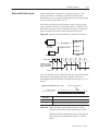
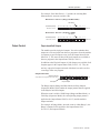
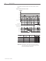
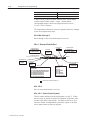
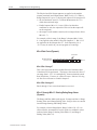
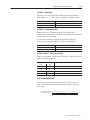
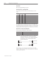
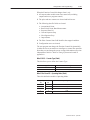
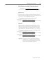
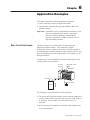
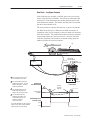
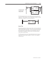
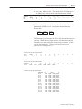
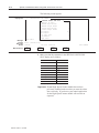
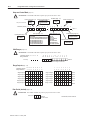
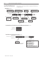
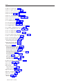
The figure below demonstrates Range Mode when a ring counter is
used.
Range Mode with Ring Counter
32,000
Range
3
500
200
1
32,767
Range
2
•
23,000
Range
4
8,000
20,000
10,000
12,500
Range
1
2
3
4
➀
Starting
Value
10,000
200
32,000
20,000
Ending
Value
12,500
8,000
500
23,000
Range
1
➀
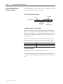
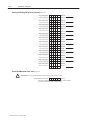
Outputs
7 6 5 4 3 2 1 0
0 0 0 0 0 0 0 1
0 0 0 0 0 0 1 0
0 0 0 0 0 1 0 0
0 0 0 0 1 0 0 1
Outputs
On
0
1
2
0 and 3
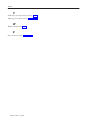
Bits 0 – 3 are Physical Outputs. Bits 4 – 7 are Soft Outputs.
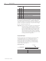
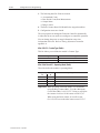
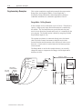
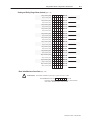
In the Range Mode, you use the counter ranges to specify the outputs
to be active within each range. Ranges may overlap. The ranges are
defined using the Starting and Ending Values (M0:e.10 – 33).
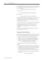
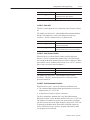
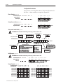
The Range Outputs fields (M0:e.3 – 8) contain the output patterns
that specify which outputs are active. Output patterns are applied to
the Output Status field (I:e.4/8–15) and output terminals when the
count is within the associated range (e.g., while in Range 2, the
Range 2 Outputs are applied). When the count is within more than
one range, the output patterns of those ranges are combined
(logically ORed). Ranges are enabled using the Valid Ranges field
(M0:e.2).
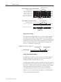
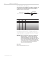
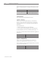
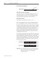
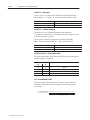
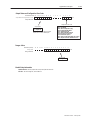
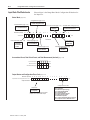
The ranges that are currently active are shown in the Ranges Active
word (I:e.6). Each range has a corresponding bit location. A 1
indicates the Accumulated Count is within the range.
Publication 1746-6.5 – April 1996