1
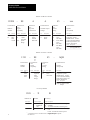
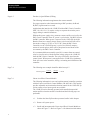
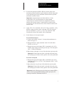
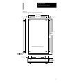
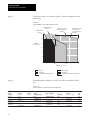
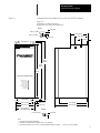
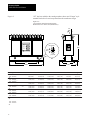
Document Update
DU
1391B-ES AC Servo Controller
User Manual
Introduction
This publication provides updated information for the 1391B-ES
Instruction Manual (1391ES-5.0, dated October, 1992). Please place this
publication with your manual for future reference.
Page 1-3
The following material is new and should be added at the end of
“Controller Description.”
The 1391-EST45 combines all of the features of the 1391B-ESAA45 with
the addition of 300% peak current capability. The controller can be ordered
with A Quad B encoder feedback and is available in the 45A size only.
Page 1-4
The following is updated Option/Modification information.
- Anti-Backlash
Provisions to use the 1388 Anti-Backlash module (1388-XA) are
available.
- Linear Accel/Decel
Linear accel/decel can be set using the CR-APG-001 Control Module.
This module provides a manually generated trapezoidal velocity profile
for up to four preset speeds. A single acceleration/deceleration rate can
be set for all speeds.
Page 2-1
The Controller Specifications shown on the following page have been
updated to include the 1391-EST45.
Document Update
1391B-ES Instruction Manual
Specific Ratings – 1391B- . . .
ESAA15
ESAA22
ESAA45
EST45
Nominal Bus Output Voltage
300V DC
300V DC
300V DC
300V DC
Continuous Current (RMS)
15A
22.5A
45A
45A
Peak Current (RMS)
30A
45A
90A
135A
Continuous Power Output
5.0 kW
7.5 kW
15.0 kW
15.0 kW
Peak Power Output
10.0 kW
15.0 kW
30.0 kW
45.0 kW
Input Circuit Breaker Rating
17A RMS
26A RMS
38A RMS
38A RMS
Circuit Breaker Interrupt Rating
(Symmetrical Amperes)
1300A
1300A
1300A
1300A
Unit Weight in lbs. (kg)
22 (9.97)
28 (12.69)
34 (15.40)
37 (16.78)
All Controller Ratings
Static Gain (A/RMS)
1.5 x Rated Motor Current / rpm
Form Factor
1.03 or less
Speed Regulation
change
0.05% (max.) of maximum motor speed with 95% load
Peak Current Limit Adjust
1391B-ES
continuous drive
20 to 300% of Rated Motor Current (to 2 times
rating, maximum)
1391-EST45
continuous drive
20 to 300% of Rated Motor Current (to 3 times
rating maximum or 135A.
Note: Peak current time varies with RMS current history.
IT
(current-time) history is used to determine available peak
current.
for 130 ms
For example: With 30A “soak,” 300% peak is available
or more with lower soak.
Controller Efficiency
(Minimum at Rated Load)
85%
Modulation Frequency
2500 Hz ±10%
Drift (Referred to Tach)
0.07 rpm /Degrees C. Maximum
Ambient Temperature
0 to 60° C (32 to 140° F)
Storage Temperature
0 to 65° C (32 to 149° F)
Input Voltage (from Transformer) Power: 230V AC, Three-Phase, 50/60 Hz ±3 Hz
Control: 36V AC CT, Single-Phase
Relative Humidity
5 to 95% Non-Condensing
Deadband
Zero
Altitude
1000 meters (3300 feet)
Integral Fan Output
50 CFM (Unloaded)
Max. RMS Short Circuit Current
(Symmetrical Amperes)
1300A
Transformer Input Tolerance
+10%, –15%
Specifications are for reference only and are subject to change without notice.
2
Document Update
1391B-ES Instruction Manual
Page 3-3 through 3-7
Several catalog number descriptions have been clarified. Descriptions for
the 1391-EST controller and Planetary Gearbox have been added.
3
Document Update
1391B-ES Instruction Manual
Bulletin 1391B-ES Controller
1391B –
First Position
ES
A
Bulletin
Number
Second Position
Speed
Capability
Code
Letter
Description
1391
StanB
dard
1391B
Third Position
Type and
Construction
Description
Blan Standard
k
1391B
ES
A
Description
A
Open
Frame,
Internal
Heat Sink
–
xxx
Sixth Position
Nominal Output
Voltage
Fifth Position
Current
Rating
Letter
Number
Description
Description
15A RMS
Cont./
30A Peak
Three character field
assigned to special
modifications. Contact
your local Allen-Bradley
Sales Representative for
further information.
Fourth Position
Letter
Extended
Speed
Range
45
Description
230V AC,
ThreePhase
A
15
22
45
Options
(if required)
22.5A RMS
Cont./
45A Peak
45A RMS
Cont./
90A Peak
Code
A13 Zero Current Option
(see Appendix D)
Bulletin 1391-EST Controller
1391
–
First Position
ES
T
45
–
AQB
Third Position
Current
Rating
Fourth Position
Bulletin
Number
Second Position
Speed
Capability
Code
Letter
Description
Description
Extended
Speed &
Peak
Torque
Range
Number
Description
EST
45A RMS
Cont./
135A Peak
Three character field
assigned to special
modifications. Contact
your local Allen-Bradley
Sales Representative for
further information.
1391
Description
Standard
EST
45
Options
(if required)
Code
Description
AQB A Quad Encoder
Output
Accessory Modules
1388
–
X
B
Module
Accessory
Description
Code Description
Code Description
1388
X
CR-APG
Blan
k
A Anti-Backlash Module w/mounting
B 1 assembly
C 1 Accel/Decel Board w/mounting rack
001 Velocity Reference Board w/mounting
rack
Bulletin No.
Accessory
Module for
1391
Linear Accel/Decel Board w/power
1
4
& 4bypreset
A combination of the 1388-XB and XC is supply
superseded
the speeds
CR-APG-001.
Description
Document Update
1391B-ES Instruction Manual
External Shunt Regulator Resistor
1391 – MOD –
Bulletin
Number
Type
SR22A
Description
Code
Description
Code
Description
MO
D
Modification Kit
SR22 Shunt Regulator Resistor for 22.5A
A
Controller
SR45 Shunt Regulator Resistor for 45A
A
Controller
1326AB Servomotor
1326
First Position
Bulletin
Number
A
B
Second Position
Third Position
Type
Letter
A
–
A
3
E
11
–
Sixth Position
Design
Fourth Position Fifth Position
Motor
Series
Length
Max. Operating
Speed
Seventh Position
Mounting &
Shaft Description
Description
Description
Description
Description
AC
Servomotor PM
Type
Factory
use only
Sequentially
lettered to
designate
frame
diameters.
Sequentially numbered to
indicate
stack
length within a given
frame size.
Cod 1391Be
ES
Cod
e
Code
Description
A
B
C
4.25”
(108 mm)
5.88”
(149 mm)
7.63”
(194 mm)
B
2000
C
3000
E
4000
G
6000
1326A – PG
B
A4
A5
A7
K4
K5
K7
Second Position
Type
Code
PG
RP
Description
Straight
Planetary
Gearbox
Right Angle
Planetary
Gearbox
A
Third Position
Used on 1326AB
Motor Series
Cod
e
A
B
C
Rated
160
0
11
200
0
21
300
0
Code Description
500
Planetary Gearbox
First Position
Bulletin
Number
–
05
A4
Eighth Position
Standard
Options
Description
Inch Combination Face/
Flange with
Keyway
NEMA/IEC
Metric Flange
with Keyway
720 lb.-in. (8.1 N-m) Holding Brake w/90V
DC Coil.
120 lb.-in. (13.6 N-m) Holding Brake w/90V
DC Coil.
400 lb.-in. (45.2 N-m) Holding Brake w/90V
DC Coil.
72 lb.-in. (8.1 N-m) Holding Brake w/24V
DC Coil.
120 lb.-in. (13.6 N-m) Holding Brake w/24V
DC Coil.
400 lb.-in. (45.2 N-m) Holding Brake w/24V
DC Coil.
–
L
B
–
21
Fourth Position
Fifth Position
Sixth Position
Gear Ratio
(Motor Shaft:Output
Shaft)
Options
Adapter
Description
Code
Code
Series A
03
05
10
15
20
30
50
100
Code Description
Series B
Series C
Description
3:1
5:1
10:1
15:1
20:1
30:1
50:1
100:1
Description
Blank No Options
LB
21
Metric
Low
Backlash
Option
5
Document Update
1391B-ES Instruction Manual
Power and Feedback Cables
1326
First Position
Bulletin
Number
Letter Description
Blan Standard
k
Cable
–
C
P
Second Position
Third Position
Type
Letter Description
C
Connector &
Cable
Assembly
A
B
T
15
Fourth Position
Fifth Position
Sixth Position
Function
Motor Size
Used On
Power Track
Cable
Cable
Length
Letter Description
Code Type
Letter
Code Description
P
Power Connection
AB Series A & B
(except
C 1326AB-B4)
T
F
U
E
Commutation &
Feedback Connection
V
845H/T Encoder
Description
All Series,
used for
high flex
applicaBlan tions
k
Standard
Cable
Series C &
1326AB-B4
All
Series
All 4.25”
(108 mm) Resolver
Packages
Page 5-3
Page 5-4
K
Connector
Kit (No
15 Cable)
30 15’ (4.6m)
50 30’ (9.1m)
100 50’ (15.2m)
150 100’
200 (30.4m)
250 150’
300 (45.7m)
200’ (61m)
250’
(76.2m)
300’
(91.4m)
In Figure 5.1, a cable specification has been added to Note 1. Note 2 has
been clarified.
1
Recommended Wire – Belden #9728 or equivalent. Maximum distance between the A Quad B
Board and the position controller is 40 feet (12.2 meters) using a 5 volt signal. For distances up to
300 feet (91 meters), 18 AWG (0.8 mm2) wire (Belden 9388 or equivalent) and an 8 to 15V DC
power supply must be used.
2
For proper operation when interconnecting to IMC Classic products (i.e. IMC 110, 12x), the B and
B (NOT) signals must be reversed.
External Shunt Regulator Resistor (TB5, Terminals 8, 9, 10)
The following sentence supplements the current material.
Bus voltage can be monitored on terminals 9 (+) and 7 (–) of TB5.
Page 5-8
Scaling information for the 1326AB-A1G motor has been added.
Table 5.C
Typical Scaling for 1326 AC Servomotors
6
S1 Switch Setting1
Motor Catalog
Number2
IC (A)
1326AB-A1G
4.5
1391B-ESAA1
5
1391B-ESAA2
2
4
3
1391B-ESAA4
5
Document Update
1391B-ES Instruction Manual
Page 5-10
The S2 switch setting for the 1326AB-A1G motor has been added.
Table 5.E
S2-2 Switch Positions
Page 5-12
Motor Catalog
Number1
S2-2 Switch
Setting
1326AB-A1G
ON
The following information has been clarified for use with IMC Classic
products.
When using the A Quad B option with Allen-Bradley IMC motion
controllers, the AMP parameters will be set according to the line count
selected. In general, one parameter must be justified when using this
device.
Important: For all IMC Classic products (IMC 110, 12x) the normal line
counts per cycle of the encoder must be divided by two since the controller
will see two markers per cycle.
Example (using an IMC 12x Controller)
With switch S3 set to 1024 lines per revolution (S3-2 OFF, S3-1 ON), the
lines per cycle of the position feedback device (located in the Feedback
Parameters File) must be 2048.
1024 x 4 = 4096 / 2 = 2048
(Quadrature)
Lines/Revolutio
2
n
Markers/Revolution
7
Document Update
1391B-ES Instruction Manual
Page 6-5
Encoder (A Quad B Board) Wiring
The following information supplements the current material.
For proper operation when interconnecting to IMC products, the B and
B (NOT) signals must be reversed.
Applications that interface the 1391B-ES with an IMC Classic Controller
(IMC 110, 120, 121, 123) require a relay to sequence the encoder power
supply during a controller shutdown.
Without this power supply relay, erroneous counts could be received by the
IMC Classic Controller when AC power is cycled to the 1391B-ES, but not
the IMC controller. When power is removed to the 1391B-ES, the AQB
Board will not have control voltage. However, the board will still receive
the encoder voltage (+5V DC or +8-15V DC) from the IMC Classic
Controller. As the 1391B-ES power is cycled, it will briefly output a
stream of encoder pulses which will be interpreted as movement of the
servomotor by the IMC Classic Controller.
It is recommended that a normally open (N.O.) contact from an external
relay be wired in series with the encoder voltage going to the 1391B-ES
from the IMC Classic Controller. The relay coil must be wired into the
control circuit. When power is not applied to the 1391B-ES, a Quadrature
Fault will occur in the controller, forcing a re-homing and calibration of the
controller.
Page 7-4
The following error example should be added to step 15.
Following Error =
Page 7-6
Velocity
Gain
=
100 ipm
1 ipm/ml
= 100 ml
Linear Accel/Decel Control Module
The following information is new and explains manual controller operation
with the Linear Accel/Decel Control Module (CR-APG-001). This module
provides adjustable acceleration/deceleration control for the 1391B-ES. Up
to four remote or local preset speeds are available.
The 1391B-ES can be manually operated with controlled trapezoidal
motion profiles when the module is installed and the following steps are
performed.
8
o 1.
Perform the Start-Up Procedure presented earlier in this chapter.
o 2.
Remove all system power.
o 3.
Install and interconnect the Linear Accel/Decel Control Module as
shown in Figure 7.3. Refer to Figure 7.4 for dimension information.
Document Update
1391B-ES Instruction Manual
o 4.
Set all of the Speed pots (SPD 1-SPD 4 or remote pots) to the
maximum clockwise position (speed minimum). Set the front panel
Accel and Decel pots to the maximum counterclockwise position
(minimum accel/decel time).
Important: All potentiometers on the module are 15 turn,
bi-directional. The Local Speed pots are setup such that
counterclockwise rotation will increase output and clockwise
rotation will decrease output. Counterclockwise rotation of the
Accel/Decel pots will decrease time, while clockwise rotation will
increase time.
o 5.
Apply 115V AC to terminals 1 & 2 of J3. Using a voltmeter, verify
that this voltage is present. Also verify that +10V DC is present
between terminals 9 (+) and 2 (–) of J1. The “ON/OFF” LED
located on the front of the module will be illuminated.
o 6.
Select Remote or Local speed control.
To select Remote Speed
a) Connect an external, 1k ohm, 1/2 watt speed potentiometer as
shown in Figure 7.3.
b) Energize the R/L 1 input (terminals 3 & 4 of J2) with either
24V DC or 115V AC.
c) Energize the speed select input, SEL 1 (terminals 1 & 2 of J2)
with the same voltage used in the previous step. The front panel
“R/L 1” LED will illuminate.
d) Repeat steps a through c for any of the other three preset speeds.
Important: If more than one speed is selected at the same time,
the resulting speed for the velocity profile will not be predictable.
To select Local Speed
e) Energize the speed select input, SEL 1 (terminals 1 & 2 of J2)
with either 24V DC or 115V AC. The front panel “SEL 1” LED
will illuminate.
f) Repeat the above step for any of the other three preset speeds.
Important: If more than one speed is selected at the same time,
the resulting speed for the velocity profile will not be predictable.
Important: In the following steps, the local speed control (SPD 1)
will be used. If your application utilizes remote speed pots, the
remote pot should be substituted for SPD 1.
9
Document Update
1391B-ES Instruction Manual
o 7.
Connect a voltmeter between terminals 11 (+) and 10 (–) of J1.
While monitoring the meter, turn the speed pot (SPD 1 or remote)
counterclockwise until the output voltage is approximately +10V
DC. Toggle the FWD/REV switch. The voltage measured should
change in polarity.
If the polarity does not change, recheck the wiring and connections
of the FWD/REV relay and switch.
Important: Changing direction with the speed input follows the
accel/decel times set on the module.
o 8.
Move the meter leads to controller terminals 1 (–) & 2 (+) of TB2.
The meter should indicate a voltage of approximately +10V DC.
o 9.
Rotate the Accel and Decel pots (located on the module front panel)
approximately 7 turns.
o 10. De-energize the SEL 1 input (terminals 1 & 2 of J2) and note the
time needed for the meter voltage to reach zero (minimum) volts.
Energize the SEL 1 input and note the time needed for the voltage to
reach +10V DC (maximum).
o 11. Adjust the Accel/Decel pots for desired ramp times (approximate
range is 0.25 to 6.5 seconds) by repeating step 10. The final ramp
time will be set during final system calibration. Rotate the speed pot
fully clockwise for minimum speed. Remove the SEL1 input.
!
ATTENTION: To protect against rapid accel/decel commands
from the module and possible machine damage or personal
injury, the “Bypass” input (terminals 19 & 20 of J2) must not be
energized. Applying 24V DC or 115V AC to this input will
remove the Accel/Decel pot settings from the circuit, causing
the output to immediately ramp to +10V DC or zero volts.
o 12. The output of the module is controlled by the “Deadman” input at
terminals 10 & 11 of J1. Applying 24V DC or 115V AC to this input
will cause the module to operate. The front panel “Dedman” LED
will be off. When this input is de-energized, the module output will
be connected to logic ground, thus disabling output. At this point the
“Dedman” LED will illuminate.
Energize the “Deadman” input with 24V DC or 115V AC.
10
Document Update
1391B-ES Instruction Manual
!
ATTENTION: During subsequent steps, the servomotor may
begin to rotate and cause incorrect machine movement when the
controller is enabled. Be prepared to remove power by opening
(MCB) or the branch circuit disconnect device if this occurs.
This movement may be due to a wiring error or system
component malfunction and must be corrected before
proceeding with this procedure. Damage to machine system
components can occur due to uncontrolled machine movements.
o 13. Apply power to the controller and module. Initiate a Start command
by selecting speed input, SEL1. Command a speed through the
speed pot, SPD 1 that represents approximately 10% of maximum
speed (i.e. 1V DC).
The motor should rotate slowly under control (following the speed
pot). If the motor is uncontrollable or rotates incorrectly, de-energize
SEL 1. Remove all power and check wiring.
If the controller current limit function is used – slowly adjust the
Current Limit potentiometer (R148) to the desired setting after the
motor is stable. Refer to Chapter 5 for more information on the this
potentiometer.
If the application requires reverse direction, use the FWD/REV
toggle switch to check operation in the reverse direction.
o 14. With a zero velocity command from the module, use the controller
Offset pot (R1) to set zero motor speed. Refer to Chapter 5 for more
information on this adjustment.
Important: The motor may begin to move slowly after a period of
time (several minutes) even though the Offset pot is set to zero.
o 15. Rotate the speed pot (SPD 1) fully counterclockwise. Adjust the
Velocity Command Scale pot (R132) to give the desired motor
speed.
o 16. Check the accel/decel rate settings at speeds selected for the
application. Refer to steps 10 & 11.
o 17. If applicable, repeat steps 6-16 for any of the other three preset
speeds
11
Document Update
1391B-ES Instruction Manual
Figure 7.3
Linear Accel/Decel Control Module Wiring
9
J1
+10V DC
1
2
Remote
Speed 1
SPD 1
24V DC or
115V AC
Direction
Change
Speed
Select 1
Local
Remote
Select 1
J2
Local
Speed 1
Direction
Change Select
J1
3
4
Remote
Speed 2
SPD 2
Local
Remote
Select 2
Speed
Select 2
FWD./REV.
+
17
–
18
Invert
Accel
Ramp
Generator
Local
Speed 2
J2
5
6
Remote
Speed 3
SPD 3
Local
Remote
Select 3
Speed
Select 3
Local
Remote
Select 4
Speed
Select 4
Remote
Speed 4
Decel
J1
SPD 4
Local
Speed 4
R/L 1 (+)
R/L 1 (–)
3
4
R/L 2 (+)
R/L 2 (–)
7
8
R/L 3 (+)
R/L 3 (–)
11
12
R/L 4 (+)
R/L 4 (–)
15
16
SEL 1 (+)
SEL 1 (–)
1
2
SEL 2 (+)
SEL 2 (–)
5
6
SEL 3 (+)
SEL 3 (–)
9
10
SEL 4 (+)
SEL 4 (–)
13
14
+
21
–
22
Deadman
J2
J1
115V AC, 50/60 HZ.
CR
Start
LS
TB4-11
TB4-12
M*
M*
CR21
TB4-13
TB4-14
DROK*
CR
* Indicates component located in controller
Required only with IMC 110, 120, 121 AND 123 controllers
11
10
to TB2-1
to TB2-2
1
2
115V AC
Power Supply
J3
STOP
TB4-17
TB4-18
Transformer
Forward
Motor
Reverse
F/R
12
M
J2
Enable
Select
TYPICAL CONTROL CIRCUIT
1
19 + Bypass
20 – Bypass
Ramp
Select
Local
Speed 3
7
8
24V DC or
115V AC
J1
Document Update
1391B-ES Instruction Manual
Figure 7.4
Linear Accel/Decel Control Module Dimensions
4.25 (108.0)
0.41 (10.3)
3.44 (87.3)
0.50 (12.7)
8.12
(206.2)
7.25
(184.2)
Dimensions are in inches (mm)
0.75 (19.1)
2.75 (69.9)
0.75
(19.1)
0.5
(12.7)
13
Document Update
1391B-ES Instruction Manual
Page 8-1
The Speed-Torque Curve shown in Figure 8.1 has been updated to 300%
rated torque.
Figure 8.1
Typical Bulletin 1326 Speed-Torque Curve
1391B-ES Rated
Speed
1391B Rated
Speed
120
xx
Peak Torque with
Nominal 15%
Low Input Line
Voltage
Peak Torque with
Nominal Input Line
Voltage
ÈÈÈÈ
ËËËËËË
ÈÈÈ
ËËËËËËËËËËË
ËËËËËË
ÈÈÈÈ
ÈÈÈ
ËËËËËËËËËËË
ËËËËËË
ÈÈÈÈ
ÈÈÈ
ËËËËËËËËËËË
ËËËËËË
ÈÈÈÈ
ÈÈÈ
ËËËËËËËËËËË
ËËËËËË
ÈÈÈÈ
ÈÈÈ
ËËËËËËËËËËË
ËËËËËË
ÈÈÈÈ
ÈÈÈ
ËËËËËËËËËËË
ËËËËËË
ÈÈÈÈ
ÈÈÈ
ËËËËËËËËËËË
ËËËËËË
ÈÈÈÈ
ÈÈÈ
ËËËËËËËËËËË
ËËËËËË
ÈÈÈÈ
ÈÈÈ
ËËËËËËËËËËË
ËËËËËË
ÈÈÈÈ
ÈÈÈ
ËËËËËËËËËËË
ËËËËËË
ÈÈÈÈ
ÈÈÈ
ËËËËËËËËËËË
ËËËËËË
ÈÈÈÈ
ÈÈÈ
ËËËËËËËËËËË
ËËËËËË
ÈÈÈÈÈÈÈ
ËËËËËËËËËËË
70%
100
Speed
(% rated rpm)
80
75%
70%
60
40
20
0
0
40
80 100 120
(Tc)
160
200
(Tp)
240
280 300
Torque (% rated)
Rated
Operation
1391B-ES Rated Operation
Page 8-3
ÈÈ
ÈÈ
Intermittent
Operation
1391B-ES Intermittent Operation
Speed comparisons with the 1391-EST drive have been added to Table
8.A.
Table 8.A
1391/1391B-ES /1391-EST Speed Comparison
Continuous
Stall
Torque
(lb.-in./
N-m)
210/23.7
310/35.0
420/47.4
420/47.4
14
Peak Stall
Torque
(lb.-in./
N-m)
630/71.2
852/96.3
1217/137.5
1260/142.4
Rated
Speed
(rpm)
4000
4000
3000
2000
Motor
Catalog Number
1326AB-C2E
1326AB-C3E
1326AB-C4C
1326AB-C4B
Servo Amplifier
Catalog Number
Amperes
at
Continuous
Torque
1391-EST45
33.2
1391-EST45
49.1
1391-EST45
46.6
1391-EST45
38.2
Rotor
Inertia
(lb.-in.-s 2/kg-m 2
)
Rated
Output
(kW)
0.14/0.015
6.9
0.22/0.024
10.0
0.29/0.032
9.3
0.29/0.032
7.5
Document Update
1391B-ES Instruction Manual
Page A-1
A dimension has been added to cover the 1391-EST45 controller.
Figure A.1
1391B-ES/1391-EST Dimensions
Dimensions are in inches and millimeters
Detail A
0.25 (6.3)
0.312 (7.9) Dia.
6.00 (152.4)
0.60 (15.2) Dia.
5.20 (132.1)
0.30 (7.6)
3.70 (93.9)
See Detail A
19.00
(482.6)
18.40
(467.4)
17.50
(444.5)
AC SERVO CONTROLLER
OVERTEMPERATURE
POWER FACTOR
CONTROL POWER
OVERVOLTAGE
UNDERVOLTAGE
CURRENT FOLDBACK
RUN ENABLE
DRIVE READY
See Detail B
4.50 (114.3)
0.67 (17.0)
9.10 (228.6)
6.20 (157.5)
0.85 (21.6)
10.64 (270.2)
6.45 (163.8)
1391-EST45 Only
Detail B
0.312 (7.9) Dia.
0.39 (9.9)
Notes:
1. Dimensions are in inches (millimeters)
1. Mounting slots and keyholes will accept 1/4-20 (7 mm) hardware.
2. A minimum spacing of 0.312" (7.9 mm) is required between adjacent controllers – 1" (25.4 mm) is recommended.
15
Document Update
1391B-ES Instruction Manual
Page A-2
“NT” has been added to the catalog numbers shown and “Europa” style
terminal blocks have been incorporated into the transfomer design.
Figure A.2
1391 Isolation Transformer Dimensions
Dimensions are in inches and (millimeters)
30°
Typ.
CONNECT
LINE INPUT
ON TERM.
120
H1 TO H3
H2 TO H4
H1 & H4
240
H2 TO H3
H1 & H4
PRIMARY
VOLTAGE
CAT. NO.
0.22 (5.6) R
FREQUENCY
POWER RATING
SECONDARY
VOLTAGE
PRIMARY VOLTAGE
SECONDARY VOLTAGE
INSULATION CLASS
NO. OF PHASES
0.53
(13.5)
VENDOR PART NO.
ALLEN-BRADLEY
VOLTAGE OUT
OF TERMINALS
+5%
X0 & X3
NOM.
X0 & X2
-5%
X0 & X1
B
Max.
0.44
(11.2) Ref.
Slot
D
E
C Max.
A Max.
Catalog Number
kVA
A
B
C
D
E
Weight
1391-T015DT
1391-T015ET/
NT
1.5
9.00 (228)
9.00 (228)
10.00 (254)
10.00 (254)
13.00 (330)
13.00 (330)
5.00 (127)
5.00 (127)
3.10 (79)
3.50 (89)
27 (12.2)
40 (18.2)
2.5
11.00 (279)
11.00 (279)
11.00 (279)
11.00 (279)
14.00 (356)
14.00 (356)
6.00 (152)
6.00 (152)
3.30 (84)
4.00 (102)
42 (19.0)
60 (27.2)
3.5
11.00 (279)
11.00 (279)
11.00 (279)
11.00 (279)
14.00 (356)
14.00 (356)
6.00 (152)
6.00 (152)
4.50 (114)
4.50 (114)
60 (27.2)
85 (38.6)
5.0
11.00 (279)
11.00 (279)
11.00 (279)
11.00 (279)
14.00 (356)
14.00 (356)
6.00 (152)
6.00 (152)
5.25 (133)
6.00 (152)
75 (34.0)
100 (45.4)
10.0
12.00 (305)
12.00 (305)
12.50 (317)
12.50 (317)
16.00 (406)
16.00 (406)
8.00 (203)
8.00 (203)
5.85 (149)
5.85 (149)
112 (50.8)
140 (63.6)
15.0
13.00 (330)
13.00 (330)
14.00 (356)
14.00 (356)
17.50 (444)
17.50 (444)
9.50 (241)
9.50 (241)
6.00 (152)
6.00 (152)
150 (68.0)
200 (90.9)
1391-T025DT
1391-T025ET/
NT
1391-T035DT
1391-T035ET/
NT
1391-T050DT
1391-T050ET/
NT
1391-T100DT
1391-T100ET/
NT
1391-T150DT
1391-T150ET/
NT
16
Document Update
1391B-ES Instruction Manual
Page A-3
The following items are included with the NEMA Type 1 Enclosure.
Qty. Description
2
Steel Mounting Channels
4
3/8-16 x 1.0 HHCS Screw
4
3/8-16 x 1.5 HHCS Screw
8
3/8 Flat Washer
8
3/8 Split Lock Washer
8
3/8-16 Hex Nuts
Appendix B
The following changes have been made to the interconnect diagrams in
Appendix B. The diagrams on the following pages have been renumbered.
Figure
Diagram
B.1
Interconnect
Control Circuit.
Description of Change
Note added to C.T. of transformer. CR2 added to
Note added to “M” Contact table. Capacitor added to
resolver.
B.2, B.3
IMC
New diagrams. CR2 and M contact added.
B.4
8400
Removed.
B.5
8600
Removed.
B.6
have been
MAX/CONTROL New diagram. Notes and terminal block designations
clarified. M contact added.
IMC-S/20x
New diagram.
IMC-S/21x
New diagram.
IMC-S/23x
New diagram.
IMC-201
New diagram.
IMC 110
New diagram.
9/Series
New information.
17
Document Update
1391B-ES Instruction Manual
Note 10 has been added.
Notes:
1)
Power Wiring unless Noted:
15A
22.5A
45A
12 AWG (3.3 mm2) min. 75C min.
10 AWG (5.3 mm2) min. 75C min.
8 AWG (8.4 mm2) min. 75C min.
2)
Signal Wiring: 18 AWG (0.8 mm2) min.
3)
Allen-Bradley Supplied Cable:
8 AWG (8.4 mm2) Motor
12 AWG (3.3 mm2) Motor
Resolver
4)
126473
126474
116190
Customer Supplied Resolver Cable:
Belden 9873 or equivalent, 20 AWG (0.5 mm2), 30 pf/ft (97.5 pf/m) max. capacitance
between conductors.
5)
Terminate shield on source end only.
6)
Do not make connections to unused pins on the resolver connector.
7)
F3 provided on 15 & 22.5a units only. 15A=KLM-10, 22.5A=FNQ 6 1/4 series B only.
8)
S2-1 ON for 1.2V/krpm, S2-1 OFF for 2.0V/krpm
9)
Current Feedback Scaling: See Chapter 5
10) On all Series D controllers (verify with controller nameplate) the secondary center tap
must not be grounded. Grounding this will cause damage to the controller.
18
Document Update
1391B-ES Instruction Manual
Figure B.1
1391B-ES/1391-EST Interconnect Diagram
19
Document Update
1391B-ES Instruction Manual
20
Document Update
1391B-ES Instruction Manual
Figure B.2
Typical IMC 110 Interconnect Diagram
1326 AC Servomotor
115V AC
K1
K2
CR
1391B-ES/EST
Servo Controller
CR2
1746-HT
Brake
(when supplied)
B1
B2
Motor
TB4
DRIVE
DRIVE
DR. RET.
SHLD
11
12
4
M
DROK, 115V AC, 1A
(CLOSED = OK)
17
18
ENCODER
CH A. HI
CH A. LO
SHLD
CH B. HI
CH B. LO
SHLD
CH Z. HI
CH Z. LO
CONTACTOR
TB4
Encoder Feedback 3
2
ENCODER
POWER
TB3
1
2
A
A
3
4
B
B
5
6
Z
Z
7
8
+5V
COMMON
Resolver
A Quad B Board
CR2
TB2
1
2
3
DRIVE
ENABLE
– VELOCITY COM.
+ VELOCITY COM.
TB2
9 +23V DC ENABLE SOURCE
10 ENABLE INPUT
TB4
13
14
ESTOP
+24V
RES. PB
RES. PB
RESET
STRING IN
STRING OUT
M
Stop
Reset P.B.
FAST I/O
Remote
Axis Hardwired Stop
CR
Overtravel
CR2
1
Refer to the 1391B-ES Interconnect Drawing for further details.
B and B (NOT) are interchanged.
3 Use Belden brand #9504 or equivalent twisted pair, shielded cable, 40 feet (12.2 meters) maximum. Shields grounded at controller only.
4 Use Belden brand #8760 or equivalent shielded cable.
2
21
Document Update
1391B-ES Instruction Manual
Figure B.3
Typical IMC 120 Interconnect Diagram 1
Termination Panel
(1771-HT)
115V AC
1326 AC Servomotor
K1
K2
ESTOP
CR
Brake
(when supplied)
+24V
LINK
RES. PB
RES. PB
RESET
STRING OUT
STRING IN
B1
B2
CR2
Stop
Reset P.B.
Motor
1391B-ES/EST Servo Controller
FAST
Remote
Axis Hardwired Stop
CR
Overtravel
TB4
CR2
11
12
M
DROK, 115V AC, 1A
(CLOSED = OK)
17
18
DRIVE 0
DRIVE
DR. RET.
SHLD
4
2
1
CONTACTOR
Resolver
TB2
+ VELOCITY COM.
– VELOCITY COM.
TB4
RESOLVER 0
13
14
M
TB2
9 +23V DC ENABLE SOURCE
10 ENABLE INPUT
ROT LO
ENCODER 0
CH A. HI
CH A. LO
SHLD
CH B. HI
CH B. LO
CH Z. HI
CH Z. LO
SHLD
ENCODER POWER
+5V
+5V RET
+15V
+15V RET
SHLD
EXT PWR
EXT RET
1
Encoder Feedback 3
2
A Quad B Board
TB3
1 A
2 A
3
4
5
6
CR2
7
8
B
B
Z
Z
TB3
+5V
COMMON
Refer to the 1391B-ES Interconnect Drawing for further details.
B and B (NOT) are interchanged.
3 Use Belden brand #9504 or equivalent twisted pair, shielded cable, 40 feet (12.2 meters) maximum. Shields grounded at controller only.
4 Use Belden brand #8760 or equivalent shielded cable.
2
22
Document Update
1391B-ES Instruction Manual
Figure B.4
Typical IMC 121, 123 and 123CR Interconnect Diagram 1
Termination Panel
(1771-HT3)
115V AC
1326 AC Servomotor
K1
K2
DRIVE ENABLE
CR
Brake
(when supplied)
ESTOP
CR2
+24V
RES. PB
RES. PB
RESET
STRING OUT
STRING IN
B1
B2
Motor
Stop
Reset P.B.
1391B-ES/EST Servo Controller
FAST IN
Remote
Axis Hardwired Stop
CR
Overtravel
TB4
11
12
CR2
IMC Module
M
CONTACTOR
17
18
DROK, 115V AC, 1A
(CLOSED = OK)
13
14
M
Resolver
TB2
9 +23V DC ENABLE SOURCE
10 ENABLE INPUT
2
1
TB2
+ VELOCITY COM. 3
– VELOCITY COM.3
TB3
A
X
I
S
x
A
X
I
S
Male D-Shell
Connector to
Axis Connector
on IMC Module
1
2
A
A
3
4
5
6
B
B
Z
Z
7
8
+5V
COMMON
2
CR2
x
A Quad B Board
1391-CAQB Cable
1
Refer to the 1391B-ES Interconnect Drawing for further details.
B and B (NOT) are interchanged.
3 If the drive is to be operated as a torque block from an IMC 121 or 123, command wires should be connected to TB2-15, 16 & 17.
2
23
Document Update
1391B-ES Instruction Manual
Figure B.5
Typical MAX/CONTROL Interconnect Diagram
115V AC
1326 AC Servomotor
K1
K2
Brake
(when supplied)
B1
B2
Motor
1391B-ES/EST Servo Controller
Remote
Axis Hardwired Stop
Overtravel
MAX/CONTROL
1, 5
TB2/3
Command Cables
15
14
2
TB4
11
12
13
14
M
CONTACTOR
M
Resolver
TB2
6
1 – VELOCITY COM.
6
2 + VELOCITY COM.
3 COMMON 6
9 ENABLE SOURCE, +23V DC
10 ENABLE
19
20
Feedback Cable 3
1
2
3
4
5
6
7
8
1
2
3
4
5
6
7
8
TB3
A
A
B
B
Z
Z
+5V
COMMON
A Quad B Board
CR-LPS-455 4
TB2/3
16
17
18
TB2/3
22
21
1
2
3
4
5
6
24
5
4
1
2
4
+5V DC
COMMON
+12V DC
–12V DC
COMMON
5/12V DC
Power Supply
COMMON
4
+24V DC
3
TB4
18
17
DROK, 115V AC, 1A
(CLOSED = OK)
Refer to the MAX/CONTROL Installation and Setup Manual (999-051) and the 1391B-ES Interconnect Drawing for further details.
Use Belden brand #8760 or equivalent shielded cable.
Use Belden brand #9504 or equivalent twisted pair, shielded cable, 40 feet (12.2 meters) maximum. Shields grounded at controller only.
Use Belden brand #9533 or equivalent shielded cable.
X-axis connections are shown – Y-axis connections (TB3) are identical.
If the drive is to be operated as a torque block, command wires should be connected to 1391B-ES TB2-15, 16 & 17.
Document Update
1391B-ES Instruction Manual
Figure B.6
Typical IMC-S/20x Interconnect Diagram
115V AC
1326 AC Servomotor
K1
K2
Brake
(when supplied)
B1
B2
Motor
1391B-ES/EST Servo Controller
Remote
Axis Hardwired Stop
Overtravel
IMC-S/20x 1, 5
(4100-20x)
Command Cables 2
TB3
TB4
11
12
13
14
16
17
9 ENABLE SOURCE, +23V DC
10 ENABLE
Feedback Cable 3
1
2
3
4
5
6
7
8
9
10
13
14
15
5
4
3
1
4
+5V DC
COMMON
+15V DC
–15V DC
COMMON
5/15V DC
Power Supply
+24V DC Power Supply
COMMON
+24V DC
– OUT – S
+ OUT + S
TB4
TB3
19
18
5
6
A Quad B Board
CR-IOPS-241 2
Denotes Screw Terminals
for Shield on
IMC S Class Chassis
4
TB3
A
A
B
B
Z
Z
+5V
COMMON
CR-LPS-455-15 4
TB3
3
Resolver
12
11
1
2
3
4
5
6
7
8
2
CONTACTOR
M
TB2
6
1 – VELOCITY COM.
6
2 + VELOCITY COM.
6
3 COMMON
TB3
1
M
17
18
DROK, 115V AC, 1A
(CLOSED = OK)
Refer to the IMC-S/20x Installation and Setup Manual (999-105) and the 1391B-ES Interconnect Drawing for further details.
Use Belden brand #8760 or equivalent shielded cable.
Use Belden brand #9504 or equivalent twisted pair, shielded cable, 40 feet (12.2 meters) maximum. Shields grounded at controller only.
Use Belden brand #9533 or equivalent shielded cable.
Axis 0 (TB3) connections are shown – Axis 1, 2, 3 connections are identical (use TB5 for Axis 1, TB4 for Axis 2, and TB6 for Axis 3).
If the drive is to be operated as a torque block, command wires should be connected to 1391B-ES TB2-15, 16 & 17.
25
Document Update
1391B-ES Instruction Manual
Figure B.7
Typical IMC-S/21x Interconnect Diagram
115V AC
1326 AC Servomotor
K1
K2
Brake
(when supplied)
B1
B2
Motor
1391B-ES/EST Servo Controller
Remote
Axis Hardwired Stop
Overtravel
IMC-S/21x 1
(4100-21x)
TB4
11
12
13
14
TB1
CONTACTOR
M
A Quad B Board
1391-SAQB Cable
3
M
1
3
4
5
6
7
8
9
10
1
2
3
4
5
6
7
8
TB3
A
A
B
B
Z
Z
+5V
COMMON
2
12
11
13
14
1
2
9
10
TB2
– VELOCITY COM. 4
+ VELOCITY COM. 4
ENABLE SOURCE, +23V DC
ENABLE
Resolver
CR-IOPS-241 2
+24V DC Power Supply
COMMON
– OUT – S
TB1
+24V DC
+ OUT + S
3
TB4
1
16
15
17
18
DROK, 115V AC, 1A
(CLOSED = OK)
Denotes Screw Terminals
for Shield on
IMC S Class Chassis
1
Refer to the IMC-S/21x Installation and Setup Manual (999-103) and the 1391B-ES Interconnect Drawing for further details.
Use Belden brand #8760 or equivalent shielded cable.
3 Axis 0 connections (TB1) are shown – Axis 1, 2, 3 connections are identical (use TB3 for Axis 1, TB4 for Axis 2 and TB5 for Axis 3).
4 If the drive is to be operated as a torque block, command wires should be connected to 1391B-ES TB2-15, 16 & 17.
2
26
Document Update
1391B-ES Instruction Manual
Figure B.8
Typical IMC-S/23x Interconnect Diagram
115V AC
1326 AC Servomotor
K1
K2
Brake
(when supplied)
B1
B2
Motor
1391B-ES/EST Servo Controller
Remote
Axis Hardwired Stop
Overtravel
4100-23x 1
CR-IOPS-241 2, 6
12
7
8
5
6
SERVO CONNECTOR
– 7
+ 1
4
10
5
11
6
12
3
9
8
2
3
4
5
6
M
CONTACTOR
M
A Quad B Board
+24V DC Power Supply
COMMON
+24V DC
– OUT – S
+ OUT + S
I/OCONNECTOR
1
TB4
11
12
13
14
Resolver
TB4
17
18
DROK, 115V AC, 1A
(CLOSED = OK)
Part of 4100-CCAQB Cable
4100-CCAQB 5 Cable
9
10
1
2
TB2
ENABLE SOURCE, +23V DC
ENABLE
– VELOCITY COM. 4
+ VELOCITY COM. 4
1
2
3
4
5
6
7
8
TB3
A
A
B
B
Z
Z
+5V
COMMON
Refer to the IMC-S/23x Installation and Setup Manual and the 1391B-ES Interconnect Drawing for further details.
Use Belden brand #8760 or equivalent shielded cable.
Axis 0 connections are shown – Axis 1, 2, 3 connections are identical.
If the drive is to be operated as a torque block, command wires should be connected to 1391B-ES TB2-15, 16 & 17.
4100-CCAQB cable assembly is a combination of the 4100-CCSxxF (servo and AQB) and 4100-CCAxxF (enable, I/O, fault). 4100-CCAQB can only
be used on 1391C-HB, 1391B-ES and 1391-DES controllers.
Separate from the 24V DC I/O power supply.
27
Document Update
1391B-ES Instruction Manual
Figure B.9
Typical IMC-201 Interconnect Diagram
115V AC
1326 AC Servomotor
K1
K2
Brake
(when supplied)
B1
B2
Motor
1391B-ES/EST Servo Controller
Remote
Axis Hardwired Stop
Overtravel
1, 5
IMC-201
(4110-201x)
Command Cables 2
TB3
TB4
11
12
13
14
16
17
9 ENABLE SOURCE, +23V DC
10 ENABLE
Feedback Cable 3
1
2
3
4
5
6
7
8
9
10
13
14
15
Denotes Screw Terminals
for Shield on
IMC-201 Chassis
5
4
1
2
4
+5V DC
COMMON
+12V DC
–12V DC
COMMON
5/12V DC
Power Supply
COMMON
4
+24V DC
3
19
18
5
6
28
A Quad B Board
TB4
TB3
4
TB3
A
A
B
B
Z
Z
+5V
COMMON
CR-LPS-455 4
TB3
3
Resolver
12
11
1
2
3
4
5
6
7
8
2
CONTACTOR
M
TB2
6
1 – VELOCITY COM.
6
2 + VELOCITY COM.
3 COMMON 6
TB3
1
M
17
18
DROK, 115V AC, 1A
(CLOSED = OK)
Refer to the IMC-201 Installation and Setup Manual (999-108) and the 1391B-ES Interconnect Drawing for further details.
Use Belden brand #8760 or equivalent shielded cable.
Use Belden brand #9504 or equivalent twisted pair, shielded cable, 40 feet (12.2 meters) maximum. Shields grounded at controller only.
Use Belden brand #9533 or equivalent shielded cable.
X Axis (TB3) connections are shown – secondary feedback (TB5) connections are identical to the TB3 connections.
If the drive is to be operated as a torque block, command wires should be connected to 1391B-ES TB2-15, 16 & 17.
Document Update
1391B-ES Instruction Manual
Figure B.10
9/ Series Interconnect Diagram
For detailed 9/Series interconnect information, please refer to the
following publications:
Controller
Publication
9/240
9/240 Integration Manual, publication 8520-4.1
9/230, 9/260, 290 9/230, 9/260 or 9/290 Integration Manual, publication 8520-6.2
29
Document Update
1391B-ES Instruction Manual
Page C-2
Outer shield has been added to the following cable information.
1326-CEUxx Encoder Feedback Cable
Wire
Color
Black
White
2
Black
Red
3
Black
Orange
4
Black
Blue
5
Black
Green
Outer Shield (Drain)
Pair
1
Page C-3
Connector
Pin
H
A
F
D
J
C
I
B
F
E
G
The table heading for the 1391-CAQB Cable has been clarified.
Cable, D-Shell
Terminal
Wire
Number
Color
30
Gauge
(AWG)
22
22
22
22
22
22
22
22
22
22
Connection on 1391B-ES Controller
Signal
Terminal
Location
Document Update
1391B-ES Instruction Manual
Page D-1
Connection of a variable DC supply was described incorrectly. In addition,
the last paragraph has been clarified. Please refer to the corrected
information below
It is possible to connect a variable 8.0V DC voltage supply to TB2-18 (+)
and 20 (–). Varying the voltage at TB2-18 will modify the current limit of
the controller as set by selector switch S1 (this rating will not exceed 200%
of the controller current rating).
Available current is proportional to the applied voltage as shown in the
table below.
Voltage at
TB2-18, 20
Peak Current 3
Percentage
0V DC or Open Circuit
3.0V DC
5.6V DC
8.0V DC 2
300% 1
200%
100%
0%
1 300%
torque of the S1 setting or 200% of drive rating, whichever is less.
between TB2-18 and 19 will also give zero current.
3 Approximate, check TP21 for an exact amount.
2 Short
The Zero Current option approximates, but may not exactly produce zero
current and torque due to tolerances inherent in the drive and components.
Offset torque may approach 10% of motor rated torque.
Figure D.1
Option Connection
Suggested Method
TB2-19
+12V DC
17.8k
TB2-18
TB2-20
Alternate Method
50k Ohm,
1/2 Watt
10-Turn Potentiometer
TB2-19
TB2-18
TB2-20
8.0
V DC
Variable
Supply
31
Document Update
1391B-ES Instruction Manual
Notes
32